EP0900628A2 - Sytème de raccord rapide - Google Patents
Sytème de raccord rapide Download PDFInfo
- Publication number
- EP0900628A2 EP0900628A2 EP98116563A EP98116563A EP0900628A2 EP 0900628 A2 EP0900628 A2 EP 0900628A2 EP 98116563 A EP98116563 A EP 98116563A EP 98116563 A EP98116563 A EP 98116563A EP 0900628 A2 EP0900628 A2 EP 0900628A2
- Authority
- EP
- European Patent Office
- Prior art keywords
- fitting
- bolts
- bolt
- fitting system
- positioning
- Prior art date
- Legal status (The legal status is an assumption and is not a legal conclusion. Google has not performed a legal analysis and makes no representation as to the accuracy of the status listed.)
- Granted
Links
Images



Classifications
-
- B—PERFORMING OPERATIONS; TRANSPORTING
- B23—MACHINE TOOLS; METAL-WORKING NOT OTHERWISE PROVIDED FOR
- B23Q—DETAILS, COMPONENTS, OR ACCESSORIES FOR MACHINE TOOLS, e.g. ARRANGEMENTS FOR COPYING OR CONTROLLING; MACHINE TOOLS IN GENERAL CHARACTERISED BY THE CONSTRUCTION OF PARTICULAR DETAILS OR COMPONENTS; COMBINATIONS OR ASSOCIATIONS OF METAL-WORKING MACHINES, NOT DIRECTED TO A PARTICULAR RESULT
- B23Q16/00—Equipment for precise positioning of tool or work into particular locations not otherwise provided for
-
- B—PERFORMING OPERATIONS; TRANSPORTING
- B23—MACHINE TOOLS; METAL-WORKING NOT OTHERWISE PROVIDED FOR
- B23Q—DETAILS, COMPONENTS, OR ACCESSORIES FOR MACHINE TOOLS, e.g. ARRANGEMENTS FOR COPYING OR CONTROLLING; MACHINE TOOLS IN GENERAL CHARACTERISED BY THE CONSTRUCTION OF PARTICULAR DETAILS OR COMPONENTS; COMBINATIONS OR ASSOCIATIONS OF METAL-WORKING MACHINES, NOT DIRECTED TO A PARTICULAR RESULT
- B23Q3/00—Devices holding, supporting, or positioning work or tools, of a kind normally removable from the machine
- B23Q3/18—Devices holding, supporting, or positioning work or tools, of a kind normally removable from the machine for positioning only
Definitions
- the invention is based on the subject defined in the preamble of claim 1.
- pallets for machine tools are standardized, their center-precise mounting on the pallet supports of the respective drilling-milling machining center is realized via a center bolt designed as a round bolt.
- the pallets are aligned on the pallet carriers using a flattened alignment bolt.
- a certain, narrowly limited compensation of different spacing dimensions of the bores in the pallet carrier to the distances between center and alignment bolts on the pallets is possible.
- the tolerance overlaps or the tolerance violations of both spacing dimensions result in situations that make it difficult to repeatable fitting and delay or that corresponding readjustments become necessary. It is characteristic of these standardized solutions that a screw connection of the joined components is state of the art.
- clamping and clamping tools are used as clamping frames can be put together so that three or four dowel bolts can be placed at the exact same distance in the middle and precisely are locked.
- These stenter frames are an additional assembly that is between the top or front machine components and the lower or rear machine component is to be arranged to both To be able to add machine components in a repeatable fit.
- the invention specified in claim 1 is therefore based on the problem of a precise fit repeatable joining with certain small differences in spacing between the Fitting bolts of the respective upper and front machine component to be joined and the Location holes in the lower and rear machine components can be compensated for without additional Tensioning frames with separate clamping and tensioning tools for fitting bolts are required
- the advantages achieved by the invention consist in particular in that, after a precise fit, on the one hand, the fitting system bolt A can be precisely centered and the fitting system bolt B can be precisely circumferentially adjusted and, on the other hand, small differences in distance dimensions can be compensated for by two radially oriented expanding adjusting elements arranged on their circumference.
- the adjustment principle is physically integrated into the fitting system bolts A and B as a linear, displacement and pressure setting.
- the tensioned machine components that are connected to each other are tensioned by the clamping shank on the fitting system bolt or additionally by at least one system bolt C.
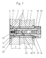
- the fitting system bolt A or B, 3 or 4 shown in Fig. 1 in the fitted and joined position consists essentially of the pre-positioning mandrel 6, equipped with a truncated cone-like chamfer, from the neck-like first positioning shaft 7, from a second positioning shaft 9, and from one Head part 10 and is received in the fitting sockets 11 and 13.
- At least one expanding adjusting element 8, designed as a radially movable ball 17, is arranged on the circumference of the positioning shaft 9.
- two or one axially directed fitting guide webs 15 are arranged symmetrically opposite the radially movable ball 17.
- the first positioning shaft 7 of the fitting system bolts A or B 3 or 4 is designed as a clamping shaft.
- the radially movable pressure balls 17 rest in axially displaced tension bevels 26 of the adapter sleeve 13, a low tension being generated by the small contact angle.
- Axial bypasse is included in the Passisystzembolzen A and B, 3 and 4, a linear-way pressure setting. It consists of the individual elements lying against one another on the end face, a screw-actuated linear drive 20, a coupling member 21, conical deflection members 22, movable in opposite directions, and a relaxation compression spring 23. Due to the linear displacement pressure setting, the pressure balls 17 lie on the inner walls of the fitting bushes 13 as well as the fitting guide webs 15 in the fit position, so that they are adjusted by point, line and surface pressures.
- the fitting system bolt A or B, 3 or 4 is secured against rotation via its head part 10 with a pin-like anti-rotation element 16 in the predetermined position in the quick-fit system.
- the pass guide webs 15 are each two raised guide and contact points, in each of the Fitting bushes 11 and 13 projecting.
- the fitting system bolts A and B, 3 and 4 is the upper one and front machine component 1 with the lower and rear machine component 2 fit and firmly connected.
- the fitting system bolt A and B, 3 and 4 shown in FIG. 1 is in the fitting holes 12 and 14 the machine components 1 and 2 recorded, adjusted, precisely fitting and firmly connected.
- Characteristic of the fitting system bolt A, 3 shown in Fig. 3 are two circumferential axially parallel fitting guide webs 15, which approach each other at a right angle about the central axis forming, symmetrically opposite the pressure ball 17.
- Fit system bolts B, 4 a pass guide web 15 is arranged axially parallel. This is the pressure ball 17 opposite.
- a fitting system bolt A is shown, the expanding adjusting element as one hollow cylindrical pressure chamber 19, shown in Fig. 5, or as a hollow cylindrical three-part Pressure chamber 19, shown in Fig. 6, is formed.
- the pressure chamber 19 is easily deformable Plasticine filled.
- the screw accommodated in the pre-positioning mandrel 6 and designed as a screw Linear drive 20 the volume of the pressure chamber is reduced via a linearly moving plate. This causes the thin-walled socket part 18 to bulge in the first positioning shaft 7. This leads to an adjustment and tension of the fitting system bolt A in the inner wall of the fitting sleeve 13.
- Der Fitting system bolt A is with the second positioning shaft 9 in the upper and front machine component 1 recorded and anchored.
- the quick pass system shown as an example in FIG. 7 consists of a pass system bolt A, 3 a fitting system bolt B, 4 and two system bolts C, 5, for tensioning the joined Machine components 1 and 2, in triangular positions.
- the fitting system bolt A, 3 is for Fitting system bolt B, 4 aligned so that the two fitting guide webs 15 on the fitting system bolt A, 3rd forming a right angle around its central axis, arranged symmetrically to the connecting line 24 are.
- the fitting guide web 15 on the fitting system bolt B, 4 is at right angles to the connecting line 24 arranged.
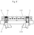
- Fig. 8 is an example by means of fitting system bolts A and B, 3 and 4 and system bolts C, 5 fit joined and connected by tension combination of a base plate Workpiece clamping device 27 shown with a pallet 28 of a drilling-milling machining center.
- a base plate 27 In the base plate 27 are fitting bushings 11 and in the pallet 28 fitting bushings 13 are introduced.
- the workpiece clamping device shown in simplified form in FIG. 9, consists of a machine component 1 designed as a double-angle clamping body, in the clamping wall of which machine components 2 designed as clamping plates are fitted and clamped with a precise fit.
- the fitting system bolts A and B, 3 and 4 are dimensioned longer than the wall thickness of the clamping wall and have pre-positioning mandrels 6 and positioning shafts 7 with radially directed adjusting elements 8 at both ends.
- the two clamping plates on the clamping wall are tensioned using system bolts C, 5.
- System bolt C Pre-positioning mandrel 7. first positioning 8th.
Landscapes
- Engineering & Computer Science (AREA)
- Mechanical Engineering (AREA)
- Jigs For Machine Tools (AREA)
- Clamps And Clips (AREA)
- Circuits Of Receivers In General (AREA)
- Stereo-Broadcasting Methods (AREA)
- Communication Control (AREA)
Applications Claiming Priority (2)
| Application Number | Priority Date | Filing Date | Title |
|---|---|---|---|
| DE19739460 | 1997-09-03 | ||
| DE19739460A DE19739460C1 (de) | 1997-09-03 | 1997-09-03 | Schnell-Paß-System für Bauteile von Werkzeugmaschinen |
Publications (3)
| Publication Number | Publication Date |
|---|---|
| EP0900628A2 true EP0900628A2 (fr) | 1999-03-10 |
| EP0900628A3 EP0900628A3 (fr) | 2000-12-20 |
| EP0900628B1 EP0900628B1 (fr) | 2003-03-05 |
Family
ID=7841712
Family Applications (1)
| Application Number | Title | Priority Date | Filing Date |
|---|---|---|---|
| EP98116563A Expired - Lifetime EP0900628B1 (fr) | 1997-09-03 | 1998-09-02 | Sytème de raccord rapide |
Country Status (3)
| Country | Link |
|---|---|
| EP (1) | EP0900628B1 (fr) |
| AT (1) | ATE233637T1 (fr) |
| DE (2) | DE19739460C1 (fr) |
Cited By (2)
| Publication number | Priority date | Publication date | Assignee | Title |
|---|---|---|---|---|
| CN104625871A (zh) * | 2015-01-28 | 2015-05-20 | 黄昌镜 | 分度夹具 |
| CN114131398A (zh) * | 2021-12-23 | 2022-03-04 | 北京新风航天装备有限公司 | 一种梯形十字键槽定位的高精度快换加工工装及加工方法 |
Families Citing this family (2)
| Publication number | Priority date | Publication date | Assignee | Title |
|---|---|---|---|---|
| DE19826328C1 (de) * | 1997-09-03 | 1999-11-25 | Hohenstein Vorrichtungsbau | Schnell-Paß-System für Bauteile von Werkzeugmaschinen |
| DE10312192B3 (de) * | 2003-03-19 | 2004-08-05 | Hohenstein Vorrichtungsbau Und Spannsysteme Gmbh | System-Niederzugspanner |
Family Cites Families (8)
| Publication number | Priority date | Publication date | Assignee | Title |
|---|---|---|---|---|
| US2707419A (en) * | 1953-08-19 | 1955-05-03 | Jergens Tool Specialty Company | Means for locating fixture plates with respect to the beds or platens of machine tools |
| US4500079A (en) * | 1984-01-30 | 1985-02-19 | General Dynamics Corporation/Convair Div. | Removable and replaceable locating pin for locating a workpiece on a sub-plate for machining |
| US4645391A (en) * | 1985-05-17 | 1987-02-24 | Fmc Corporation | Work set up method and apparatus |
| DE3801654A1 (de) * | 1988-01-21 | 1989-07-27 | Schunk Fritz Gmbh | Ausrichtsystem |
| DE3919077C1 (fr) * | 1989-06-10 | 1990-07-26 | Erowa Ag, Reinach, Ch | |
| DE3929931A1 (de) * | 1989-09-08 | 1991-03-14 | Heckler & Koch Gmbh | Justiervorrichtung |
| DE4135418A1 (de) * | 1991-10-26 | 1993-05-27 | Emil Stark Gmbh | Spannvorrichtung zum spannen einer aufspannplatte auf einer traegerplatte fuer bearbeitungsmaschinen |
| DE4307342C2 (de) * | 1993-03-09 | 1994-12-08 | Erowa Ag | Einrichtung zum positionsdefinierten Aufspannen eines Werkstücks am Arbeitsplatz einer Bearbeitungsmaschine |
-
1997
- 1997-09-03 DE DE19739460A patent/DE19739460C1/de not_active Expired - Fee Related
-
1998
- 1998-09-02 AT AT98116563T patent/ATE233637T1/de not_active IP Right Cessation
- 1998-09-02 DE DE59807363T patent/DE59807363D1/de not_active Expired - Fee Related
- 1998-09-02 EP EP98116563A patent/EP0900628B1/fr not_active Expired - Lifetime
Cited By (2)
| Publication number | Priority date | Publication date | Assignee | Title |
|---|---|---|---|---|
| CN104625871A (zh) * | 2015-01-28 | 2015-05-20 | 黄昌镜 | 分度夹具 |
| CN114131398A (zh) * | 2021-12-23 | 2022-03-04 | 北京新风航天装备有限公司 | 一种梯形十字键槽定位的高精度快换加工工装及加工方法 |
Also Published As
| Publication number | Publication date |
|---|---|
| EP0900628B1 (fr) | 2003-03-05 |
| EP0900628A3 (fr) | 2000-12-20 |
| DE59807363D1 (de) | 2003-04-10 |
| DE19739460C1 (de) | 1999-02-11 |
| ATE233637T1 (de) | 2003-03-15 |
Similar Documents
| Publication | Publication Date | Title |
|---|---|---|
| DE10155077B4 (de) | Wiederholgenaue Spanneinrichtung | |
| EP1321221B1 (fr) | Dispositif de fixation avec mandrin de serrage et porte-pièce pouvant être fixé de façon amovible à celui-ci | |
| EP2134490B1 (fr) | Porte-outil | |
| EP3983169B1 (fr) | Dispositif de serrage et dispositif de maintien de pièce comprenant un dispositif de serrage | |
| EP1595641B1 (fr) | Dispositif de serrage avec mandrin et palette fixé de façon amovible sur le mandrin. | |
| EP2105226B2 (fr) | Mandrin magnétique | |
| EP0753368B1 (fr) | Dispositif de serrage pour la fixation relative précise de 2 pièces | |
| CH716410B1 (de) | Spanneinrichtung mit einem Spannfutter und einem lösbar daran fixierbaren Werkstückträger. | |
| EP3263274A1 (fr) | Dispositif de serrage et système de serrage | |
| EP4194141A1 (fr) | Dispositif de serrage | |
| EP3219437A1 (fr) | Dispositif de retenue de pièce et procédé pour munir un dispositif de retenue de pièce d'une pièce | |
| EP2918379A1 (fr) | Dispositif d'embrayage pour un appareil de manipulation | |
| EP0450383A1 (fr) | Dispositif de serrage et de centrage | |
| EP0365557A1 (fr) | Agencement de positionnement et son utilisation. | |
| EP0287777B1 (fr) | Dispositif de serrage d'outils ou de pièces, ayant une manche cylindrique | |
| EP3616831A1 (fr) | Dispositif de serrage | |
| DE19917146A1 (de) | Nullpunktspannsystem | |
| EP0870580B1 (fr) | Etau | |
| EP2177296B1 (fr) | Dispositif de serrage extensible | |
| DE102014001963B4 (de) | Spannvorrichtung zum reproduzierbar, lagengenauen Festspannen von Werkstücken | |
| DE19739460C1 (de) | Schnell-Paß-System für Bauteile von Werkzeugmaschinen | |
| DE4202989C2 (de) | Flexibles Vorrichtungssystem in modularer Bauweise | |
| DE19826328C1 (de) | Schnell-Paß-System für Bauteile von Werkzeugmaschinen | |
| DE202004018168U1 (de) | Aus einer Spannvorrichtung und einem Werkstückträger gebildete Einheit | |
| DE19756215C2 (de) | Schnell-Paß-System für Bauteile von Werkzeugmaschinen |
Legal Events
| Date | Code | Title | Description |
|---|---|---|---|
| PUAI | Public reference made under article 153(3) epc to a published international application that has entered the european phase |
Free format text: ORIGINAL CODE: 0009012 |
|
| AK | Designated contracting states |
Kind code of ref document: A2 Designated state(s): AT CH DE ES FR GB IT LI |
|
| AX | Request for extension of the european patent |
Free format text: AL;LT;LV;MK;RO;SI |
|
| 17P | Request for examination filed |
Effective date: 19990719 |
|
| PUAL | Search report despatched |
Free format text: ORIGINAL CODE: 0009013 |
|
| AK | Designated contracting states |
Kind code of ref document: A3 Designated state(s): AT BE CH CY DE DK ES FI FR GB GR IE IT LI LU MC NL PT SE |
|
| AX | Request for extension of the european patent |
Free format text: AL;LT;LV;MK;RO;SI |
|
| RIC1 | Information provided on ipc code assigned before grant |
Free format text: 7B 23Q 16/00 A, 7F 16B 21/10 B, 7B 23Q 7/14 B, 7F 16B 21/16 B, 7B 23Q 3/18 B |
|
| AKX | Designation fees paid |
Free format text: AT CH DE ES FR GB IT LI |
|
| 17Q | First examination report despatched |
Effective date: 20020422 |
|
| GRAH | Despatch of communication of intention to grant a patent |
Free format text: ORIGINAL CODE: EPIDOS IGRA |
|
| GRAH | Despatch of communication of intention to grant a patent |
Free format text: ORIGINAL CODE: EPIDOS IGRA |
|
| GRAA | (expected) grant |
Free format text: ORIGINAL CODE: 0009210 |
|
| AK | Designated contracting states |
Designated state(s): AT CH DE ES FR GB IT LI |
|
| PG25 | Lapsed in a contracting state [announced via postgrant information from national office to epo] |
Ref country code: IT Free format text: LAPSE BECAUSE OF FAILURE TO SUBMIT A TRANSLATION OF THE DESCRIPTION OR TO PAY THE FEE WITHIN THE PRE;WARNING: LAPSES OF ITALIAN PATENTS WITH EFFECTIVE DATE BEFORE 2007 MAY HAVE OCCURRED AT ANY TIME BEFORE 2007. THE CORRECT EFFECTIVE DATE MAY BE DIFFERENT FROM THE ONE RECORDED.SCRIBED TIME-LIMIT Effective date: 20030305 |
|
| REG | Reference to a national code |
Ref country code: GB Ref legal event code: FG4D Free format text: NOT ENGLISH |
|
| REG | Reference to a national code |
Ref country code: CH Ref legal event code: EP |
|
| REF | Corresponds to: |
Ref document number: 59807363 Country of ref document: DE Date of ref document: 20030410 Kind code of ref document: P |
|
| GBT | Gb: translation of ep patent filed (gb section 77(6)(a)/1977) | ||
| PGFP | Annual fee paid to national office [announced via postgrant information from national office to epo] |
Ref country code: GB Payment date: 20030829 Year of fee payment: 6 Ref country code: DE Payment date: 20030829 Year of fee payment: 6 Ref country code: CH Payment date: 20030829 Year of fee payment: 6 |
|
| PGFP | Annual fee paid to national office [announced via postgrant information from national office to epo] |
Ref country code: FR Payment date: 20030901 Year of fee payment: 6 |
|
| PG25 | Lapsed in a contracting state [announced via postgrant information from national office to epo] |
Ref country code: AT Free format text: LAPSE BECAUSE OF NON-PAYMENT OF DUE FEES Effective date: 20030902 |
|
| PG25 | Lapsed in a contracting state [announced via postgrant information from national office to epo] |
Ref country code: ES Free format text: LAPSE BECAUSE OF FAILURE TO SUBMIT A TRANSLATION OF THE DESCRIPTION OR TO PAY THE FEE WITHIN THE PRESCRIBED TIME-LIMIT Effective date: 20030930 |
|
| ET | Fr: translation filed | ||
| PLBE | No opposition filed within time limit |
Free format text: ORIGINAL CODE: 0009261 |
|
| STAA | Information on the status of an ep patent application or granted ep patent |
Free format text: STATUS: NO OPPOSITION FILED WITHIN TIME LIMIT |
|
| 26N | No opposition filed |
Effective date: 20031208 |
|
| PG25 | Lapsed in a contracting state [announced via postgrant information from national office to epo] |
Ref country code: GB Free format text: LAPSE BECAUSE OF NON-PAYMENT OF DUE FEES Effective date: 20040902 |
|
| PG25 | Lapsed in a contracting state [announced via postgrant information from national office to epo] |
Ref country code: LI Free format text: LAPSE BECAUSE OF NON-PAYMENT OF DUE FEES Effective date: 20040930 Ref country code: CH Free format text: LAPSE BECAUSE OF NON-PAYMENT OF DUE FEES Effective date: 20040930 |
|
| PG25 | Lapsed in a contracting state [announced via postgrant information from national office to epo] |
Ref country code: DE Free format text: LAPSE BECAUSE OF NON-PAYMENT OF DUE FEES Effective date: 20050401 |
|
| GBPC | Gb: european patent ceased through non-payment of renewal fee |
Effective date: 20040902 |
|
| REG | Reference to a national code |
Ref country code: CH Ref legal event code: PL |
|
| PG25 | Lapsed in a contracting state [announced via postgrant information from national office to epo] |
Ref country code: FR Free format text: LAPSE BECAUSE OF NON-PAYMENT OF DUE FEES Effective date: 20050531 |
|
| REG | Reference to a national code |
Ref country code: FR Ref legal event code: ST |