EP0900680B1 - Canal de guidage d'une vitre coulissante de véhicule - Google Patents
Canal de guidage d'une vitre coulissante de véhicule Download PDFInfo
- Publication number
- EP0900680B1 EP0900680B1 EP98116955A EP98116955A EP0900680B1 EP 0900680 B1 EP0900680 B1 EP 0900680B1 EP 98116955 A EP98116955 A EP 98116955A EP 98116955 A EP98116955 A EP 98116955A EP 0900680 B1 EP0900680 B1 EP 0900680B1
- Authority
- EP
- European Patent Office
- Prior art keywords
- door glass
- glass run
- grooves
- door
- body portion
- Prior art date
- Legal status (The legal status is an assumption and is not a legal conclusion. Google has not performed a legal analysis and makes no representation as to the accuracy of the status listed.)
- Expired - Lifetime
Links
- 239000011521 glass Substances 0.000 title claims description 180
- 239000000463 material Substances 0.000 claims description 13
- 230000004927 fusion Effects 0.000 claims description 2
- 239000011248 coating agent Substances 0.000 description 18
- 238000000576 coating method Methods 0.000 description 18
- -1 for example Polymers 0.000 description 9
- 239000002344 surface layer Substances 0.000 description 7
- 239000004743 Polypropylene Substances 0.000 description 5
- 150000001336 alkenes Chemical class 0.000 description 5
- 238000001125 extrusion Methods 0.000 description 5
- 229920001155 polypropylene Polymers 0.000 description 5
- 230000002159 abnormal effect Effects 0.000 description 4
- 230000015572 biosynthetic process Effects 0.000 description 4
- 239000005357 flat glass Substances 0.000 description 4
- 238000007789 sealing Methods 0.000 description 4
- 229920002725 thermoplastic elastomer Polymers 0.000 description 4
- 229920002943 EPDM rubber Polymers 0.000 description 3
- 239000004698 Polyethylene Substances 0.000 description 3
- 229920000573 polyethylene Polymers 0.000 description 3
- PPBRXRYQALVLMV-UHFFFAOYSA-N Styrene Chemical compound C=CC1=CC=CC=C1 PPBRXRYQALVLMV-UHFFFAOYSA-N 0.000 description 2
- 239000000203 mixture Substances 0.000 description 2
- 239000000178 monomer Substances 0.000 description 2
- JRZJOMJEPLMPRA-UHFFFAOYSA-N olefin Natural products CCCCCCCC=C JRZJOMJEPLMPRA-UHFFFAOYSA-N 0.000 description 2
- 239000004800 polyvinyl chloride Substances 0.000 description 2
- 229920000915 polyvinyl chloride Polymers 0.000 description 2
- 229920005989 resin Polymers 0.000 description 2
- 239000011347 resin Substances 0.000 description 2
- 238000005507 spraying Methods 0.000 description 2
- 229920002803 thermoplastic polyurethane Polymers 0.000 description 2
- XUIMIQQOPSSXEZ-UHFFFAOYSA-N Silicon Chemical compound [Si] XUIMIQQOPSSXEZ-UHFFFAOYSA-N 0.000 description 1
- 239000000428 dust Substances 0.000 description 1
- 230000000694 effects Effects 0.000 description 1
- 229920001971 elastomer Polymers 0.000 description 1
- 230000007774 longterm Effects 0.000 description 1
- 238000000034 method Methods 0.000 description 1
- 230000002093 peripheral effect Effects 0.000 description 1
- 239000004576 sand Substances 0.000 description 1
- 229910052710 silicon Inorganic materials 0.000 description 1
- 239000010703 silicon Substances 0.000 description 1
- 229920003002 synthetic resin Polymers 0.000 description 1
- 239000000057 synthetic resin Substances 0.000 description 1
Images


Classifications
-
- B—PERFORMING OPERATIONS; TRANSPORTING
- B60—VEHICLES IN GENERAL
- B60J—WINDOWS, WINDSCREENS, NON-FIXED ROOFS, DOORS, OR SIMILAR DEVICES FOR VEHICLES; REMOVABLE EXTERNAL PROTECTIVE COVERINGS SPECIALLY ADAPTED FOR VEHICLES
- B60J10/00—Sealing arrangements
- B60J10/20—Sealing arrangements characterised by the shape
- B60J10/27—Sealing arrangements characterised by the shape having projections, grooves or channels in the longitudinal direction
-
- B—PERFORMING OPERATIONS; TRANSPORTING
- B60—VEHICLES IN GENERAL
- B60J—WINDOWS, WINDSCREENS, NON-FIXED ROOFS, DOORS, OR SIMILAR DEVICES FOR VEHICLES; REMOVABLE EXTERNAL PROTECTIVE COVERINGS SPECIALLY ADAPTED FOR VEHICLES
- B60J10/00—Sealing arrangements
- B60J10/15—Sealing arrangements characterised by the material
- B60J10/17—Sealing arrangements characterised by the material provided with a low-friction material on the surface
-
- B—PERFORMING OPERATIONS; TRANSPORTING
- B60—VEHICLES IN GENERAL
- B60J—WINDOWS, WINDSCREENS, NON-FIXED ROOFS, DOORS, OR SIMILAR DEVICES FOR VEHICLES; REMOVABLE EXTERNAL PROTECTIVE COVERINGS SPECIALLY ADAPTED FOR VEHICLES
- B60J10/00—Sealing arrangements
- B60J10/70—Sealing arrangements specially adapted for windows or windscreens
- B60J10/74—Sealing arrangements specially adapted for windows or windscreens for sliding window panes, e.g. sash guides
Definitions
- the present invention relates to a door glass run to be attached on a door frame of a car door.
- a door glass run 3 (hereinafter, simply referred to as a glass run) is attached on a door frame 2 of a door 1 of a car along an inner side of the door frame 2 for guiding up/down movement of a door glass 5 and sealing a gap between a circumferential edge of the closed door glass 5 and the door frame 2.
- front and rear vertical extension frame portions 2A of the door flame 2 are provided in a door body and the glass run 3 is attached also on each of the vertical extension frame portions 2A.
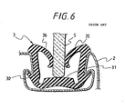
- a glass run 3 As such a glass run 3, generally, a glass run having such a configuration as shown in Fig. 6 is used, in which lips 35 and 36 extend, in a direction to face each other, from the opposite ends, at an opening side, of a body portion 30 which is U-shaped in section.
- the door glass 5 moves up/down in the state where a peripheral edge of the door glass 5 is in contact with, its opposite surfaces, between the lips 35 and 36 of the glass run 3, and an end surface of the door glass 5 is also in contact with a bottom surface 31 of the glass run 3.
- the bottom surface 31 of the glass run 3 is subject to smoothening treatment by spraying urethane resin, silicon resin, or the like so as to improve the slidability of the door glass 5.
- urethane resin silicon resin, or the like
- foreign matters such as sand, dust, and the like may come into the body portion 30 of the glass run 3 and may deposit on the bottom surface 31 to thereby gradually lower the slidability of the door glass 5.
- US-A-5 265 377 which forms the basis of the preambles of the appended independent claims discloses a door glass run wherein equidistant grooves formed in the bottom surface of the glass run are inclined at a predetermined angle with respect to the sliding direction of the window glass. Such oblique grooves form communications between the outside and the inside of the window glass, by which the sealing might be negatively influenced.
- DE-A-2 127 097 discloses a glass run with an elastomeric profile within which guide strips are embedded to guide the window glass. Sealing of the window glass is performed by equidistant sealing ribs being integrally formed in a bottom surface of the elastomeric profile. Grooves formed between the ribs are formed such that if the grooves are filled with foreign matters the contact area between the foreign matters and the end surface of the door glass is big in comparison to the contact area of the end surface of the door glass with the tip ends of the ribs.
- Claims 2 to 10 are directed towards further advantageous features of the inventive glass run.
- the end surface of the door glass moves up/down while slightly transversely vibrating with respect to the central line of a bottom surface of a glass run because a car body vibrates or because the curvature of a door frame becomes slightly different from that of the door glass in accordance with the vertical position of the door glass.
- the present invention has paid attention onto the fact that foreign matters which deposit on a bottom surface of a glass run are swept out to the opposite sides by the end surface of door glass when the door glass vibrates transversely.
- the foreign matters which have deposited on the central portion of the bottom surface of the glass run are swept into/out of the opposite sides when the door glass moves up/down, and the great part of the foreign matters are fallen into the large grooves formed in the opposite portions on the bottom surface to be thereby discharged.
- the groove formed in the central portion of the bottom surface is small and, hence, even if the groove is filled with the foreign matters, the glass sliding resistance does not become large so that no abnormal sounds are generated.
- foreign matters which have deposited on the bottom surface of the glass run are fallen into the grooves formed in the opposite portions on the bottom surface to be thereby discharged. Further, in case no groove is formed in the central portion of the bottom surface with which the door glass comes into slide-contact, the quantity of foreign matters which may remain against sweeping-out is very small and hence the sliding resistance is hardly increased.
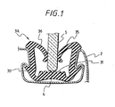
- Fig. 1 shows a glass run 3A according to a first embodiment of the present invention. This glass run is attached on the vertical frame portion of the door frame 2 of the car shown in Fig. 5.
- the glass run 3A is formed of an extrusion molding of rubber, for example, EPDM (ethylene-propylene-diene) rubber, and has a fundamental configuration in which lips 35 and 36 extend from the opposite ends, at the opening side, of a body portion 30 U-shaped in section.
- a bottom wall is designed to be thicker than the remaining portion.
- a door glass 5 has a thickness of about 4 mm and an end surface arch-shaped in section. The door glass 5 moves up/down in the state where the door glass 5 is in contact with the lips 35 and 36 at its inner and outer surfaces, and a central portion of a side edge surface of the door glass 5 is in contact with a bottom surface 31 of the glass run 3A.
- a plurality of uniform grooves 4 are formed in a bottom surface 31 so as to extend longitudinally at predetermined intervals widthwise to thereby reduce a sliding area between an end surface of door glass 5 and the bottom surface 31 and to thereby bury part of foreign matters entering the glass run into the grooves 4.
- Each of the grooves is shaped in the form of an inverted triangle in section.
- this glass run 3A by formation of the grooves 4 in the bottom surface 31 of the glass run 3A, the area of slide-contact between a door glass end surface and the bottom surface 31 of the glass run can be reduced, and foreign matters which have deposited on the bottom surface 31 of the glass run body portion 30 can be discharged into the grooves to thereby reduce the sliding resistance of the door glass against the bottom surface of the glass run.
- Fig. 2 shows a glass run 3B according to a second embodiment of the invention, which is provided for solving the aforementioned problem.
- a plurality of mutually-parallel grooves 4a, 4b, and 4c are formed in the bottom surface 31 to extend longitudinally at equal intervals widthwise.
- Each of the grooves is shaped in the form of an inverted triangle in section and the grooves are designed so as to have sectional areas which become larger in order from the groove formed in a widthwise central portion of the bottom surface 31 to the groove formed on each of the opposite sides of the central portion of the bottom surface 31.
- the groove 4a is formed in the widthwise central position of the bottom surface 31; the grooves 4c are formed in the widthwise opposite-end portions; and the grooves 4b are formed in the intermediate portions between the grooves 4a and 4c.
- the opening width and depth of the groove 4a are selected to be about 0.2 - 0.3mm and about 0.2 - 0. 3mm, respectively.
- the opening width and depth of the groove 4c are selected to be about 0.7 - 1.0mm and about 0.4 - 0.6mm, respectively.
- the opening width and depth of the groove 4b are selected to be intermediate values between those of the grooves 4a and 4c.
- the widths of the land portions between the grooves 4a, 4b, and 4c are selected to be an equal value of 0.7 - 0.8mm.
- the bottom surface having the grooves 4a, 4b, and 4c formed therein and the surfaces of the lips 35 and 36 are subject to smoothening treatment S with urethane resin.
- the sectional shape of each of the grooves is not limited to such an inverted triangle but it may be shaped into a quadrangle.
- the end surface of the door glass 5 moves up/down while it is in slide-contact with the land portions of the bottom surface 31 of the glass run 3A when the door glass 5 moves up/down.
- the end surface of the door glass 5 is in slide-contact only with the land portions between the grooves so that an influence of foreign matters attached on the bottom surface 31 is reduced. Even if a large quantity of foreign matters have deposited, the foreign matters on the land portions are swept out right and left by the end surface of the door glass 5 transversely vibrating when the door glass is moved up/down, so that the foreign matters fall into the grooves 4a, 4b, and 4c.
- the contact area of the foreign matters with the end surface of the door glass 5 is small so that the sliding resistance is not largely increased and no abnormal sounds are generated.
- the maximum width of transverse movement of the central portion of the end surface of the door glass 5 to contact with the bottom surface 31 of the glass run 3B by a transverse vibration of the door glass 5 is ranged within the distance between the grooves 4a and 4b. Because the groove 4b is larger than the groove 4a, the groove 4b is not completely filled with foreign matters before long-term use. Thus, even if the groove 4b is filled with foreign matters, the foreign matters hardly gives a large influence on the sliding resistance of the door glass 5. Since the foreign matters swept out by the door glass 5 are received into the grooves 4b and 4c, there is a function to prevent the swept-out foreign matters from falling to deposit again on the central portion of the glass run bottom surface 31.
- the glass run 3C in the case of the glass run 3C, foreign matters which have deposited on a bottom surface central portion with which the door glass 5 is in slide-contact are discharged into opposite-side grooves 4d and 4e.
- the glass run 3C since no groove is formed in the bottom surface central portion, the glass sliding.area is slightly increased correspondingly, in comparison with the glass run 3B.
- there is no groove in the central portion which may be filled with foreign matters. Accordingly, the end surface of the door glass 5 never come into slide-contact with the accumulated foreign matters in the central groove.
- the glass run having the grooves formed in its bottom surface may be integrally molded with olefin thermoplastic elastomer.
- Fig. 4 shows a glass run 3D according to a fourth embodiment of the invention.
- a surface layer 32 which is formed of a material different from that of a glass run body and which is superior in smooth property is formed on the surface of a bottom wall of the body portion 30 so as to face an end surface of the door glass 5, and grooves for receiving foreign matters are formed in an upper surface 31 constituting a bottom wall of the glass run 3D.
- a surface layer 32a which is formed of a different material in place of carrying-out of smoothening treatment S and which is superior in smooth property may be formed on the surface of each of lips 35 and 36.
- the surface layer 32, 32a is formed of olefin group resin, for example, polyethylene, polypropylene, etc., or olefin group thermoplastic elastomer, and the surface layer 32 has the same grooves 4a, 4b, and 4c as those in the glass run 3D. Further, the upper surface 31 on the surface layer 32 may be formed in the same manner as that in the case of the glass run 3C.
- the surface layer 32 is integrally formed with an upper surface of a bottom wall of the glass run 3D by extrusion molding or by sticking of a tape member and fusion bonding thereafter. Incidentally, in the glass run 3D, it is not necessary to make the surface layer 32 be subjected to smoothening treatment by spraying or the like.
- the glass run body may be formed by using synthetic resin such as PVC (polyvinyl chloride) or the like, or olefin group thermoplastic elastomer, besides the foregoing EPDM rubber.
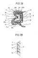
- Fig. 7 shows a glass run 3E according to a fifth embodiment of the present invention, to be attached on the door frame 2 shown in Fig. 5 so that the portion is positioned along the vertical frame portion of the door frame 2.
- the glass run 3E is obtained by extrusion-molding with TPO (olefin thermoplastic elastomer), and integrally provided with a body portion 30 substantially U-shaped in section; seal lips 35 and 36 extending from opened front ends of opposite side walls 312a and 312b of the body portion 30 so as to face each other; and mole lips 33a and 33b extending from the opened front ends of the opposite side walls 312a and 312b along the outsides of the opposite walls 312a and 312b reversely to the seal lips 35 and 36.
- TPO polypropylene
- the glass run 3E is attached on the door frame 2 in such a manner that the body portion 30 is fitted onto a channel portion 20 formed in an inner circumference of the door flame 2, and the mole lips 33a and 33b formed inside and outside a car are pressed against inside and outside walls 21a and 21b of the channel portion 20 opposite to the mole lips 33a and 33b respectively.
- a coating film 6 of a sliding material is formed on the bottom surface 31 and the whole surface extending from the facing surfaces of the seal lips 35 and 36 to front ends of the mole lips 33a and 33b in the same manner as that in the case of the glass run 3B which is the second embodiment illustrated in Fig. 2.
- the seal lips 35 and 36 is in slide-contact with the door glass 5 while being in contact with the door glass 5 when the door glass 5 moves up/down, and the coating film 6 acts also as a coating member of a designed surface.
- grooves 4d and 4e are formed in the bottom surface 31 so as to be in slide-contact with the end surface of the door glass 5 and are designed so as to have sectional areas which become larger in order from the groove formed in the widthwise central portion of the bottom surface 31 to the groove formed on each of the opposite sides of the central portion in the bottom surface 31. Further, also the surfaces of the groves 4d and 4e are covered with the same coating film 6 as described above so that the grooves 4d and 4e are not filled with foreign matters.
- the material of the coating film 6 it is possible to use a mixture material obtained by mixing TPO with polypropylene or polyethylene which is fusible to TPO, or a mixture material obtained in such a manner that TPO and styrene are blended with each other and the thus obtained material is mixed with polypropylene, etc.
- Polypropylene gives hardness, brightness and a glass slidability to a coating film.
- a polyethylene monomer or a polypropylene monomer may be also used as the coating film 6 may be extrusion-molded at the same time as the glass run 3E is extrusion-molded.
- the extrusion-molded coating film 6 is strongly bonded to the body portion 30 of the glass run 3E of TPO and is extremely glossy with improved brightness in comparison with TPO extrusion moldings.
- the extrusion-molded glass run of TPO in which the whole designed surface appearing as the exterior surface is coated with the coating film 6 is connected at the molded corner portion of TPO, a difference in color tone between the extrusion moldings and the molded corner portion can be hardly perceived and hence the whole glass run has a sense of feeling of being united into one body to be attractive.
- the coating film 6 is extrusion-molded simultaneously with the glass run body portion 30 to thereby obtain the smoothness of the glass run 3E against the door glass 5 and the improvement of the exterior quality at the same time. Further, the coating film 6 is hardly peeled off.
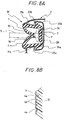
- Fig. 8 shows a glass run 3F according to a sixth embodiment of the present invention.
- the glass run 3F is different from the glass run 3E in that there are provided no mole lips.
- Protrusions 34a and 34b are formed in opposite sides of a bottom portion of the glass run 3F to be engaged with stage portions 22a and 22b formed on the opposite side walls 21a and 21b of the channel portion 20 of the door flame 2 so that the glass run 3F is prevented from coming off.
- the structure of the glass run 3F is substantially the same as that of the glass run 3E and hence parts of the glass run 3F identical to those of the glass run 3D are correspondingly referenced.
- a coating film 7 of a sliding material is formed on a bottom surface 31 and the whole designed surface which extends from glass slide-contacting portions of seal lips 35 and 36 to base portions of the same.
- the coating film 7 acts also as the designed coating member.
- the method of forming the coating film 7 and the quality of the sliding material are the same as those in the case of the glass run 3E and formation of the coating film 7 gives the same function and effects as those in the case of the glass run 3E.
- the glass run with a body portion 30 having hardness of about 75 - 80 Hs is used.
- the hardness of the coating film of the sliding material is selected to be about 35 - 45D (Shore D type hardness) in view of the glass slidability, the damage resistance property, and the contact property with a door glass surface.
- the area of slide-contact between a door glass end surface and the bottom surface of the glass run can be reduced, and foreign matters which have deposited on the bottom surface of the glass run can be discharged into the grooves to thereby reduce the sliding resistance of the door glass against the bottom surface of the glass run.
- the sliding resistance of the door glass is not largely increased by the accumulated foreign matters.
Landscapes
- Engineering & Computer Science (AREA)
- Mechanical Engineering (AREA)
- Seal Device For Vehicle (AREA)
- Window Of Vehicle (AREA)
Claims (11)
- Coulisse de vitre de portière adaptée pour être fixée sur un cadre de portière (2) d'une portière de voiture pour guider le mouvement vers le haut/vers le bas d'une vitre de portière, comprenant :caractérisée en ce que lesdites rainures (4 ; 4a, 4b, 4c; 4d, 4e) s'étendent de manière longitudinale à intervalles prédéterminés en largeur et sont formées de manière à avoir des zones sectionnelles qui deviennent plus larges dans l'ordre à partir d'une ou de deux rainure(s) (4 ; 4a; 4d) formée(s) dans une partie centrale en largeur de ladite surface inférieure (31) vers celles formées sur chacun des côtés opposés de ladite partie centrale de ladite surface inférieure.une partie formant corps (30) adaptée pour être fixée sur le cadre de portière (2) et ayant une ouverture et une surface inférieure (31) avec laquelle une surface d'extrémité de la vitre de portière (5) est en contact ;des lèvres (35, 36) disposées à des extrémités opposées de l'ouverture de ladite partie formant corps de manière à être en contact avec la vitre de portière des surfaces opposées de celle-ci ; etune pluralité de rainures (4 ; 4a, 4b, 4c ; 4d, 4e) étant formée dans ladite surface inférieure de ladite partie formant corps,
- Coulisse de vitre de portière selon la revendication 1, dans laquelle une largeur d'ouverture et une profondeur de chacune desdites rainures (4 ; 4a, 4b, 4c ; 4d, 4e) s'élargissent dans l'ordre à partir de la rainure (4 ; 4a) formée dans une partie centrale en largeur de ladite surface inférieure vers celle formée sur chacun des côtés opposés de ladite surface inférieure.
- Coulisse de vitre de portière selon la revendication 1 ou la revendication 2,
caractérisée en ce que
une partie centrale en largeur de ladite surface inférieure (31) de ladite partie formant corps (30) avec laquelle l'extrémité de la vitre de portière (5) est en contact est faite de manière à être une surface plate, et
ladite pluralité de rainures (4d, 4e) est formée à des intervalles en largeur prédéterminés sur chacune des parties latérales opposées de ladite partie de surface plate centrale. - Coulisse de vitre de portière selon la revendication 3, dans laquelle la surface plate dans la partie centrale est conçue pour avoir une largeur qui est égale à la largeur de la vibration latérale de la partie centrale de la surface d'extrémité de la vitre de portière (5) qui est en contact avec la surface plate lorsque la vitre de portière (5) se déplace vers le haut/vers le bas.
- Coulisse de vitre de portière selon l'une quelconque des revendications 1 à 4, dans laquelle chacune desdites rainures (4 ; 4a-4e) est mise en forme sous la forme d'un triangle renversé dans la partie.
- Coulisse de vitre de portière selon l'une quelconque des revendications 1 à 5, dans laquelle lesdites rainures (4; 4a-4e) sont mutuellement parallèles.
- Coulisse de vitre de portière selon l'une quelconque des revendications 1 à 6, dans laquelle ladite surface inférieure (31) de la partie formant corps (30) comprend un matériau (S ; 6 ; 32) différent de celui de la partie formant corps (30), qui a un meilleur caractère lisse et qui est capable d'être lié par fusion à la partie formant corps, et lesdites rainures (4a-4e) sont formées sur ledit matériau.
- Coulisse de vitre de portière selon la revendication 7, comprenant en outre des couches lisses (S ; 32a) formées sur lesdites lèvres (35, 36), lesdites couches lisses comprenant le même matériau que celui de ladite surface inférieure.
- Coulisse de vitre de portière selon la revendication 8, dans laquelle lesdites couches lisses (S; 32a) couvrent toutes les zones des surfaces extérieures desdites lèvres.
- Coulisse de vitre de portière selon la revendication 3, caractérisée en ce que
ladite partie formant corps (30) ayant une partie en forme de U avec ladite ouverture, et ladite surface inférieure (31) avec ladite partie de surface en largeur centrale plate, ladite partie de surface en largeur centrale plate s'étendant en largeur pour couvrir une zone sur laquelle une bordure de la vitre de portière se dresse et vibre latéralement lorsque ladite partie formant corps est fixée sur le cadre de la portière et associée de manière fonctionnelle à la vitre de portière. - Coulisse de vitre de portière adaptée pour être fixée sur un cadre de portière (2) d'une portière de voiture pour guider le mouvement vers le haut/vers le bas d'une vitre de portière, comprenant :caractérisée en ce queune partie formant corps (30) adaptée pour être fixée sur le cadre de portière (2) et ayant une ouverture et une surface inférieure (31) avec laquelle une extrémité de la vitre de portière (5) est en contact ;des lèvres (35, 36) disposées à des extrémités opposées de l'ouverture de ladite partie formant corps de manière à être en contact avec la vitre de portière des surfaces opposées de celle-ci ; etune pluralité de rainures (4d, 4e) étant formée à intervalles prédéterminés dans ladite surface inférieure (31),
une partie centrale en largeur de ladite surface
inférieure (31) de ladite partie formant corps (30) avec laquelle l'extrémité de la vitre de portière (5) est en contact est faite de manière à être une surface plate, et
ladite pluralité de rainures (4d, 4e) s'étend de manière longitudinale et est formée à intervalles en largeur prédéterminés sur chacune des parties latérales opposées de ladite partie de surface plate centrale.
Priority Applications (1)
| Application Number | Priority Date | Filing Date | Title |
|---|---|---|---|
| EP03019995A EP1384615B1 (fr) | 1997-09-08 | 1998-09-08 | Canal de guidage d'une vitre coulissante de véhicule |
Applications Claiming Priority (3)
| Application Number | Priority Date | Filing Date | Title |
|---|---|---|---|
| JP261017/97 | 1997-09-08 | ||
| JP26101797 | 1997-09-08 | ||
| JP26101797A JP3336926B2 (ja) | 1997-09-08 | 1997-09-08 | 自動車用ドアガラスラン |
Related Child Applications (1)
| Application Number | Title | Priority Date | Filing Date |
|---|---|---|---|
| EP03019995A Division EP1384615B1 (fr) | 1997-09-08 | 1998-09-08 | Canal de guidage d'une vitre coulissante de véhicule |
Publications (2)
| Publication Number | Publication Date |
|---|---|
| EP0900680A1 EP0900680A1 (fr) | 1999-03-10 |
| EP0900680B1 true EP0900680B1 (fr) | 2004-06-30 |
Family
ID=17355901
Family Applications (2)
| Application Number | Title | Priority Date | Filing Date |
|---|---|---|---|
| EP03019995A Expired - Lifetime EP1384615B1 (fr) | 1997-09-08 | 1998-09-08 | Canal de guidage d'une vitre coulissante de véhicule |
| EP98116955A Expired - Lifetime EP0900680B1 (fr) | 1997-09-08 | 1998-09-08 | Canal de guidage d'une vitre coulissante de véhicule |
Family Applications Before (1)
| Application Number | Title | Priority Date | Filing Date |
|---|---|---|---|
| EP03019995A Expired - Lifetime EP1384615B1 (fr) | 1997-09-08 | 1998-09-08 | Canal de guidage d'une vitre coulissante de véhicule |
Country Status (4)
| Country | Link |
|---|---|
| US (1) | US6138414A (fr) |
| EP (2) | EP1384615B1 (fr) |
| JP (1) | JP3336926B2 (fr) |
| DE (2) | DE69824797T2 (fr) |
Families Citing this family (18)
| Publication number | Priority date | Publication date | Assignee | Title |
|---|---|---|---|---|
| JP2000025462A (ja) * | 1998-07-15 | 2000-01-25 | Toyoda Gosei Co Ltd | ガラスラン |
| US6451411B1 (en) * | 1999-09-08 | 2002-09-17 | Schlegel Corporation | Weatherseal having a substrate with an adhesive overflow containment groove |
| JP3812310B2 (ja) * | 1999-11-30 | 2006-08-23 | 豊田合成株式会社 | ガラスラン |
| KR20030027588A (ko) * | 2001-09-29 | 2003-04-07 | 현대자동차주식회사 | 자동차 파워 윈도우의 안전장치 |
| DE10313601B4 (de) * | 2003-03-26 | 2008-02-14 | Metzeler Automotive Profile Systems Gmbh | Dichtungsanordnung zum Abdichten und Führen einer bewegbaren Fensterscheibe, insbesondere eines Kraftfahrzeugs |
| US20050120633A1 (en) * | 2003-11-26 | 2005-06-09 | Tomohiro Takase | Glass run for vehicle |
| JP4375072B2 (ja) * | 2004-03-23 | 2009-12-02 | 豊田合成株式会社 | 自動車用ガラスラン |
| US20060117706A1 (en) * | 2004-11-12 | 2006-06-08 | Hooker Richard D | Simple mirror sail seal for fixed sail construction |
| JP2006182210A (ja) * | 2004-12-28 | 2006-07-13 | Toyoda Gosei Co Ltd | ガラスラン |
| JP4735416B2 (ja) * | 2006-05-25 | 2011-07-27 | 豊田合成株式会社 | ガラスランの取付構造 |
| US7762614B2 (en) * | 2006-09-28 | 2010-07-27 | Toyoda Gosei Co., Ltd. | Glass run |
| JP4521677B2 (ja) * | 2007-04-02 | 2010-08-11 | トキワケミカル工業株式会社 | 自動車用ウェザーストリップ |
| US8495841B2 (en) * | 2009-08-07 | 2013-07-30 | Magna Mirrors Of America, Inc. | Window assembly for vehicle |
| US8776435B2 (en) | 2012-07-03 | 2014-07-15 | Magna Mirrors Of America, Inc. | Window assembly for vehicle |
| EP2722209A3 (fr) * | 2012-10-22 | 2018-01-03 | Henniges Automotive Sealing Systems North America, Inc. | Ensemble de joint d'étanchéité pour assurer l'étanchéité entre un cadre et un élément de fermeture et procédé de production de celui-ci |
| JP2015009634A (ja) | 2013-06-27 | 2015-01-19 | トヨタ自動車株式会社 | 車両用プレスドア構造及びドアガラスラン |
| CN104512229B (zh) * | 2015-01-10 | 2017-01-04 | 许崇霞 | 一种玻璃导槽密封条 |
| US10167664B2 (en) | 2015-09-09 | 2019-01-01 | Magna Mirrors Of America, Inc. | Window assembly for vehicle |
Family Cites Families (13)
| Publication number | Priority date | Publication date | Assignee | Title |
|---|---|---|---|---|
| DE2127097A1 (de) * | 1971-06-01 | 1972-12-14 | Volkswagenwerk Ag, 3180 Wolfsburg | Schiebefensterführung, insbesondere für Fahrzeuge mit versenkbaren Fenstern |
| DE2807115C2 (de) * | 1978-02-20 | 1979-12-06 | Schlegel Gmbh, 2000 Hamburg | Verfahren zum Aufbringen eines selbstklemmenden Profilstreifens auf einen Halteflansch und Profilstreifen zur Durchführung des Verfahrens |
| DE3480913D1 (de) * | 1983-07-18 | 1990-02-08 | Toyota Motor Co Ltd | Tuerkonstruktion im kraftfahrzeug. |
| FR2551826B3 (fr) * | 1983-09-12 | 1985-08-23 | Fiat Auto Spa | Joint pour une glace descendante de fermeture d'une fenetre presentant une resistance aerodynamique basse et portiere pour vehicule muni d'un tel joint |
| JPH0349929Y2 (fr) * | 1985-05-22 | 1991-10-24 | ||
| JPH062448B2 (ja) * | 1987-03-30 | 1994-01-12 | 豊田合成株式会社 | 自動車用ドアガラスラン |
| JP2586241B2 (ja) * | 1991-06-07 | 1997-02-26 | 豊田合成株式会社 | ガラスラン |
| US5306537A (en) * | 1991-12-20 | 1994-04-26 | The Standard Products Company | Wear resistant coating for glass run channel |
| US5228740A (en) * | 1992-08-07 | 1993-07-20 | Chardon Rubber Company | Vehicular window frame assembly for sliding window panes |
| US5247764A (en) * | 1992-08-26 | 1993-09-28 | Ford Motor Company | Molded, bristled glass retainer |
| JP2568723Y2 (ja) * | 1992-08-28 | 1998-04-15 | 豊田合成株式会社 | 自動車用ドアガラスラン |
| JP2919747B2 (ja) * | 1994-08-30 | 1999-07-19 | 鬼怒川ゴム工業株式会社 | シール部材用のスペーサ |
| US5628150A (en) * | 1996-03-26 | 1997-05-13 | The Standard Products Company | Glass run channel with a composite reinforcement |
-
1997
- 1997-09-08 JP JP26101797A patent/JP3336926B2/ja not_active Expired - Fee Related
-
1998
- 1998-09-08 EP EP03019995A patent/EP1384615B1/fr not_active Expired - Lifetime
- 1998-09-08 DE DE69824797T patent/DE69824797T2/de not_active Expired - Lifetime
- 1998-09-08 DE DE69834442T patent/DE69834442T2/de not_active Expired - Lifetime
- 1998-09-08 US US09/149,104 patent/US6138414A/en not_active Expired - Lifetime
- 1998-09-08 EP EP98116955A patent/EP0900680B1/fr not_active Expired - Lifetime
Also Published As
| Publication number | Publication date |
|---|---|
| EP1384615A1 (fr) | 2004-01-28 |
| EP0900680A1 (fr) | 1999-03-10 |
| JP3336926B2 (ja) | 2002-10-21 |
| DE69824797D1 (de) | 2004-08-05 |
| DE69834442D1 (de) | 2006-06-08 |
| DE69834442T2 (de) | 2007-04-12 |
| US6138414A (en) | 2000-10-31 |
| EP1384615B1 (fr) | 2006-05-03 |
| DE69824797T2 (de) | 2005-07-14 |
| JPH1178537A (ja) | 1999-03-23 |
Similar Documents
| Publication | Publication Date | Title |
|---|---|---|
| EP0900680B1 (fr) | Canal de guidage d'une vitre coulissante de véhicule | |
| EP0978404B1 (fr) | Joint d'étanchéité | |
| US4970102A (en) | Weather stripping, particularly for the movable glass of an automotive vehicle | |
| US6843024B2 (en) | Weather strip including core-removal slot | |
| CA1234592A (fr) | Profile-guide pour vitre de portiere d'un vehicule automobile | |
| CA1322216C (fr) | Bande d'etancheite de vitrage comportant une glissiere rigide a faible friction | |
| US20010001916A1 (en) | Glass run of an automobile | |
| US20080148646A1 (en) | Weather strip for motor vehicle | |
| KR100365840B1 (ko) | 웨더 스트립 | |
| US5155938A (en) | Door glass run for motor vehicle | |
| US5233805A (en) | Molding for automotive front glass and molding apparatus | |
| EP1481831A1 (fr) | Guidage de vitre pour véhicule automobile | |
| EP0972666B1 (fr) | Canal de guidage d'une vitre | |
| US6792718B2 (en) | Vehicle seal | |
| US6601345B2 (en) | Sealing structure for vehicle door | |
| JP3960967B2 (ja) | ガラスランチャンネル組立体 | |
| JP3427635B2 (ja) | ウエザストリップの型接続方法 | |
| JPH11180157A (ja) | 自動車用ドアガラスラン | |
| JP3693148B2 (ja) | 樹脂製外装部品のシール材取付け構造 | |
| JP2000016090A (ja) | 硝子案内縁材 | |
| JPH09150634A (ja) | 自動車用ガラスラン | |
| JPH09164849A (ja) | 車両用ドアガラスラン | |
| JP2007223394A (ja) | ドアウエザストリップ | |
| JPH07117583A (ja) | 複層成形押出品 |
Legal Events
| Date | Code | Title | Description |
|---|---|---|---|
| PUAI | Public reference made under article 153(3) epc to a published international application that has entered the european phase |
Free format text: ORIGINAL CODE: 0009012 |
|
| 17P | Request for examination filed |
Effective date: 19980908 |
|
| AK | Designated contracting states |
Kind code of ref document: A1 Designated state(s): DE FR GB |
|
| AX | Request for extension of the european patent |
Free format text: AL;LT;LV;MK;RO;SI |
|
| AKX | Designation fees paid |
Free format text: DE FR GB |
|
| 17Q | First examination report despatched |
Effective date: 20010509 |
|
| GRAH | Despatch of communication of intention to grant a patent |
Free format text: ORIGINAL CODE: EPIDOS IGRA |
|
| GRAS | Grant fee paid |
Free format text: ORIGINAL CODE: EPIDOSNIGR3 |
|
| GRAA | (expected) grant |
Free format text: ORIGINAL CODE: 0009210 |
|
| AK | Designated contracting states |
Kind code of ref document: B1 Designated state(s): DE FR GB |
|
| REG | Reference to a national code |
Ref country code: GB Ref legal event code: FG4D |
|
| REF | Corresponds to: |
Ref document number: 69824797 Country of ref document: DE Date of ref document: 20040805 Kind code of ref document: P |
|
| ET | Fr: translation filed | ||
| PLBE | No opposition filed within time limit |
Free format text: ORIGINAL CODE: 0009261 |
|
| STAA | Information on the status of an ep patent application or granted ep patent |
Free format text: STATUS: NO OPPOSITION FILED WITHIN TIME LIMIT |
|
| 26N | No opposition filed |
Effective date: 20050331 |
|
| PGFP | Annual fee paid to national office [announced via postgrant information from national office to epo] |
Ref country code: FR Payment date: 20100921 Year of fee payment: 13 |
|
| PGFP | Annual fee paid to national office [announced via postgrant information from national office to epo] |
Ref country code: GB Payment date: 20100908 Year of fee payment: 13 |
|
| PGFP | Annual fee paid to national office [announced via postgrant information from national office to epo] |
Ref country code: DE Payment date: 20100901 Year of fee payment: 13 |
|
| GBPC | Gb: european patent ceased through non-payment of renewal fee |
Effective date: 20110908 |
|
| REG | Reference to a national code |
Ref country code: FR Ref legal event code: ST Effective date: 20120531 |
|
| REG | Reference to a national code |
Ref country code: DE Ref legal event code: R119 Ref document number: 69824797 Country of ref document: DE Effective date: 20120403 |
|
| PG25 | Lapsed in a contracting state [announced via postgrant information from national office to epo] |
Ref country code: DE Free format text: LAPSE BECAUSE OF NON-PAYMENT OF DUE FEES Effective date: 20120403 |
|
| PG25 | Lapsed in a contracting state [announced via postgrant information from national office to epo] |
Ref country code: GB Free format text: LAPSE BECAUSE OF NON-PAYMENT OF DUE FEES Effective date: 20110908 Ref country code: FR Free format text: LAPSE BECAUSE OF NON-PAYMENT OF DUE FEES Effective date: 20110930 |