EP0901009A2 - Procédé, élément de capteur, et capteur de gaz pour la détection du dioxyde d'azote - Google Patents
Procédé, élément de capteur, et capteur de gaz pour la détection du dioxyde d'azote Download PDFInfo
- Publication number
- EP0901009A2 EP0901009A2 EP98250303A EP98250303A EP0901009A2 EP 0901009 A2 EP0901009 A2 EP 0901009A2 EP 98250303 A EP98250303 A EP 98250303A EP 98250303 A EP98250303 A EP 98250303A EP 0901009 A2 EP0901009 A2 EP 0901009A2
- Authority
- EP
- European Patent Office
- Prior art keywords
- light
- porous body
- nitrogen dioxide
- dioxide gas
- sensor element
- Prior art date
- Legal status (The legal status is an assumption and is not a legal conclusion. Google has not performed a legal analysis and makes no representation as to the accuracy of the status listed.)
- Granted
Links
Images


Classifications
-
- G—PHYSICS
- G01—MEASURING; TESTING
- G01N—INVESTIGATING OR ANALYSING MATERIALS BY DETERMINING THEIR CHEMICAL OR PHYSICAL PROPERTIES
- G01N21/00—Investigating or analysing materials by the use of optical means, i.e. using sub-millimetre waves, infrared, visible or ultraviolet light
- G01N21/75—Systems in which material is subjected to a chemical reaction, the progress or the result of the reaction being investigated
- G01N21/77—Systems in which material is subjected to a chemical reaction, the progress or the result of the reaction being investigated by observing the effect on a chemical indicator
- G01N21/78—Systems in which material is subjected to a chemical reaction, the progress or the result of the reaction being investigated by observing the effect on a chemical indicator producing a change of colour
- G01N21/783—Systems in which material is subjected to a chemical reaction, the progress or the result of the reaction being investigated by observing the effect on a chemical indicator producing a change of colour for analysing gases
-
- G—PHYSICS
- G01—MEASURING; TESTING
- G01N—INVESTIGATING OR ANALYSING MATERIALS BY DETERMINING THEIR CHEMICAL OR PHYSICAL PROPERTIES
- G01N31/00—Investigating or analysing non-biological materials by the use of the chemical methods specified in the subgroup; Apparatus specially adapted for such methods
- G01N31/22—Investigating or analysing non-biological materials by the use of the chemical methods specified in the subgroup; Apparatus specially adapted for such methods using chemical indicators
- G01N31/223—Investigating or analysing non-biological materials by the use of the chemical methods specified in the subgroup; Apparatus specially adapted for such methods using chemical indicators for investigating presence of specific gases or aerosols
-
- Y—GENERAL TAGGING OF NEW TECHNOLOGICAL DEVELOPMENTS; GENERAL TAGGING OF CROSS-SECTIONAL TECHNOLOGIES SPANNING OVER SEVERAL SECTIONS OF THE IPC; TECHNICAL SUBJECTS COVERED BY FORMER USPC CROSS-REFERENCE ART COLLECTIONS [XRACs] AND DIGESTS
- Y10—TECHNICAL SUBJECTS COVERED BY FORMER USPC
- Y10T—TECHNICAL SUBJECTS COVERED BY FORMER US CLASSIFICATION
- Y10T436/00—Chemistry: analytical and immunological testing
- Y10T436/17—Nitrogen containing
- Y10T436/177692—Oxides of nitrogen
- Y10T436/178459—Only nitrogen dioxide
-
- Y—GENERAL TAGGING OF NEW TECHNOLOGICAL DEVELOPMENTS; GENERAL TAGGING OF CROSS-SECTIONAL TECHNOLOGIES SPANNING OVER SEVERAL SECTIONS OF THE IPC; TECHNICAL SUBJECTS COVERED BY FORMER USPC CROSS-REFERENCE ART COLLECTIONS [XRACs] AND DIGESTS
- Y10—TECHNICAL SUBJECTS COVERED BY FORMER USPC
- Y10T—TECHNICAL SUBJECTS COVERED BY FORMER US CLASSIFICATION
- Y10T436/00—Chemistry: analytical and immunological testing
- Y10T436/17—Nitrogen containing
- Y10T436/177692—Oxides of nitrogen
- Y10T436/179228—Both nitrogen oxide and dioxide
Definitions
- the present invention relates to a nitrogen dioxide gas sensing method, a nitrogen dioxide gas sensor element, and a nitrogen dioxide gas sensor using the same.
- SO 2 and NO x are produced by combustion of fossil fuels and cause acid rain and photo-chemical smog.
- environmental standards are set for these pollutants, e.g., the concentration of atmospheric NO 2 .
- Gas concentration measurement is performed by an automatic measurement method in regular monitoring stations at different locations. As an environmental standard, the average value per hour in a day is approximately 60 ppb or less.
- a method using a sensor tube gas meter is also developed to perform short-time measurement on the spot and is difficult to use in cumulative measurement. Furthermore, an operator must go to the measurement site, and personal errors occur in reading colors. In many instances, interference of other gases or disturbance is a problem.
- a common simple measurement method is to receive air by using a pump, collect NO x gas by directly collecting it into a sampling bag (a direct collection method), by using a solid-state adsorbent (a solid collection method), or by collecting it into an absorbing solution (a liquid collection method), and analyze the collected gas by gas chromatography.
- a direct collection method collects NO x gas by directly collecting it into a sampling bag
- a solid-state adsorbent a solid collection method
- a liquid collection method absorbing solution
- the direct collection method it is difficult to store gas because the size of the sampling bag is limited.
- the solid collection method and the liquid collection method require a process of sensing the collected gas.
- a passive sampler for environmental measurement has attracted attention.
- Examples of an NO x passive sampler are a nitration plate method and a triethanolamine (TEA) batch method.
- TAA triethanolamine
- the effects of the wind speed, temperature, and humidity are examined to examine the quantitativeness.
- a general approach of measurement after sampling is to clean the sample to form a solution and analyze the solution by ion chromatography or absorptiometric analysis.
- these samplers require cumbersome processes such as cleaning after collection and before analysis.
- an NO x gas sensing method has been proposed.
- NO 2 gas is reacted with a sensing reagent adsorbed in pores of a porous body as a transparent matrix adsorbent, and the transmitted UV-visible absorption spectrum is measured by a spectrophotometer to sense the amount of NO 2 .
- a side reaction occurs in this sensing method because a highly reactive material is used as the sensing reagent. Consequently, the sensitivity of the reaction product with NO 2 as a target substance does not increase in the UV-visible absorption spectrum. Additionally, the side reaction product disturbs the UV-visible absorption spectrum to make high accuracy impossible to obtain.
- the conventional methods require large expensive apparatuses to accurately sense nitrogen dioxide gas of the order of ppb in accordance with the environmental standards. Also, these methods are too cumbersome to allow easy detection of nitrogen dioxide gas.
- a mixture of a diazotizing reagent which reacts with nitrous ions to produce a diazo compound, a coupling reagent which couples with the diazo compound to produce an azo dye, and an acid is placed in pores of a transparent porous body to prepare a sensor element.
- the light transmittance of this sensor element is measured to calculate the first transmittance.
- the sensor element is then exposed to air to be measured for a predetermined time. After that, the light transmittance of the sensor element is measured to calculate the second transmittance. Nitrogen dioxide gas in the air to be measured is sensed in accordance with the difference between the first and second transmittances.
- the diazotizing reagent diazotizes nitrous ions produced by nitrogen dioxide adsorbed to pores of the sensor element to produce a diazo compound.
- the coupling reagent couples with this diazo compound to produce an azo dye. Consequently, the sensor element colors to make a difference between the first and second transmittances. This allows detection of the nitrogen dioxide gas.
- a nitrogen dioxide gas sensor element comprises a transparent porous body, a diazotizing reagent placed in pores of the porous body to react with nitrous ions to produce a diazo compound, a coupling reagent placed together with the diazotizing reagent in the pores of the porous body to couple with a diazo compound to produce an azo dye, and an acid placed together with the diazotizing reagent in the pores of the porous body
- the diazotizing reagent reacts with nitrous ions produced by the nitrogen dioxide gas to produce a diazo compound.
- the coupling reagent couples with this diazo compound to produce an azo dye. Consequently, the nitrogen dioxide gas sensor element colors.
- a nitrogen dioxide gas sensor comprises a light-emitting unit for emitting light, a light-sensing unit having a light-receiving surface opposed to a light-emitting surface of the light-emitting unit to output an electrical signal corresponding to a light amount received by the light-receiving surface, a sensor element inserted between the light-emitting unit and the light-sensing unit, and an electric meter for measuring the state of the output electrical signal from the light-sensing unit.
- the sensor element comprises a transparent porous body, a diazotizing reagent placed in pores of the porous body to react with nitrous ions to produce a diazo compound, a coupling reagent placed together with the diazotizing reagent in the pores of the porous body to couple with the diazo compound to produce an azo dye, and an acid placed together with the diazotizing reagent in the pores of the porous body.
- the diazotizing reagent reacts with nitrous ions produced by the nitrogen dioxide gas to produce a diazo compound.
- the coupling reagent couples with this diazo compound to produce an azo dye. Consequently, the nitrogen dioxide gas sensor element colors.
- the light emitted from the light-emitting unit enters the light-sensing unit via the sensor element.
- the electric meter measures the color change of the sensor element as a change in the output electrical signal from the light-sensing unit.
- a nitrogen dioxide (NO 2 ) gas sensing method will be described below.
- a method of manufacturing a nitrogen dioxide gas sensor element will be described below.
- sulfanilic acid (SA) as an aromatic amine serving as a diazotizing reagent
- DMNA N,N-dimethylnaphthylamine
- SA sulfanilic acid
- DMNA N,N-dimethylnaphthylamine
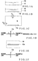
- a porous body 103 as porous glass having an average pore-diameter of 4 nm was immersed in this sensing reagent solution 101.
- Vycor 7930 manufactured by Corning Glass Works was used as this porous body 103.
- the average pore-size of this Vycor 7930 was 4 nm.
- the chip dimensions of the porous body 103 were 8 (mm) x 8 (mm) and a thickness of 1 (mm).
- Vycor 7930 was borosilicate glass. An alkali component and other components mainly consisting of silicon were separated by heating. In this state, an acid treatment was performed to elute the alkali component and form a porous body. Since the acid treatment was performed during the course of manufacture, pores of Vycor 7930 had an acidic environment. That is, an acid previously existed. If the pores of the porous body are not acidic, acid cleaning or the like is previously performed to make an acid present as an acidic environment in the pores. The porous body in this state need only have, e.g., pH 1.
- a porous body made from an organic polymer can also be used.
- the porous body 103 as described above was immersed in the sensing reagent solution 101 for two hours. After the pores of the porous body 103 were impregnated with the sensing reagent solution, the porous body 103 was air-dried. Finally, as shown in Fig. 1C, the porous body 103 was dried by leaving it in a nitrogen gas flow for a half day to manufacture a sensor element 103a.
- the sensor element is a plate-like element in the above embodiment, a fiber-like element is also usable.
- FIG. 1D the absorbance in the direction of thickness of this sensor element 103a was measured.
- reference symbol I 0 denotes incoming signal light intensity
- I transmitted light intensity.
- the sensor element 103a was exposed for three hours to air 104 as an object to be sensed in which 300-ppb nitrogen dioxide existed.
- the sensor element 103a was extracted from the air 104, and, as shown in Fig. 1F, the absorbance in the thickness direction of the sensor element 103a was again measured.
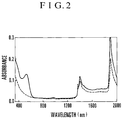
- Fig. 2 shows the results of these two absorbance measurements. No measurements were performed at a transmitted light measurement wavelength of 350 nm or less because the porous glass (Vycor 7930) forming the sensor element adsorbed the wavelength. Referring to Fig. 2, the absorbance measurement result before the sensor element was exposed to the air to be sensed is indicated by the broken line, and the absorbance measurement result after the element was exposed is indicated by the solid line.
- Both the solid and broken lines show an absorption considered as absorption by water near 1,350 and 1,900 nm, respectively. This absorption changed with the humidity of the air to be sensed and the time during which the sensor element was left to stand. Therefore, in this nitrogen dioxide gas sensing method using the sensor element of the first embodiment, it is determined that the effective measurement wavelength range is 350 to 1,000 nm.
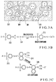
- the sensor element as a porous body is a transparent matrix absorbent, as shown in Fig. 3A, having a plurality of pores 301 having an average pore-diameter of 20 nm or less.
- a diazotizing reagent and a coupling reagent are placed together with an acid in the holes 301 of this sensor element (porous body) 302.
- the pores adsorb water in the air to form a thin water film 303. Consequently, this thin film 303 of an aqueous solution in which the diazotizing reagent, coupling reagent, and acid are dissolved is formed on the inner walls of the pores 301 of the sensor element 302 as this porous body.
- Nitrogen dioxide molecules 304 entering the pores 301 encounter these components to cause the following two reactions.
- sulfanilic acid 312 as the diazotizing reagent reacts with (diazotizes) nitrous ions 311 produced by dissolving nitrogen oxide in water to produce a diazo compound 313.
- This diazo compound couples with N,N-dimethylnaphthylamine 314 as the coupling reagent to produce an azo compound (coupling compound) 315.
- an azo compound (azo dye) has light absorption in a wavelength region of 200 to 2,000 nm.
- the azo compound 315 shown in Fig. 3C has an absorption wavelength around 500 to 550 nm. This agrees with the results shown in Fig. 2.
- the azo compound can be sensed (determined) by measuring its absorption spectrum by using, e.g., a spectrophotometer (absorptiometer).
- a spectrophotometer aborptiometer
- Diazotization is a process in which aromatic primary amine (ArNH 2 ) and NO 2 - react with each other to form a diazo compound (ArN 2 + ) in the presence of two or more equivalents of an acid.
- ArNH 2 aromatic primary amine
- NO 2 - NO 2 -
- ArN 2 + diazo compound
- the above reaction basically occurs only in nitrogen dioxide gas. Since this reaction is ArNH 2 + NO 2 - + 2H + ⁇ ArN 2 + + 2H 2 O, it theoretically requires two equivalents of an acid. That is, as described previously, the diazotizing reagent and the coupling reagent together with a necessary amount of an acid must be placed in (carried by) the pores of the porous body.
- the above reaction can also take place in a gas phase, water necessarily exists in an actual environment as mentioned earlier. Essentially, therefore, a thin water film exists in the pores of the sensor element, and the reaction occurs in this aqueous solution.
- nitrogen dioxide gas can be indirectly measured by measuring the light absorption of the azo compound produced as a result of the adsorption of the nitrogen dioxide gas.
- the porous body is made from a material which transmits light in the light absorption wavelength region of the azo compound, the light absorption characteristic of the porous body adsorbing nitrogen dioxide gas is measured. Consequently, the adsorbed nitrogen dioxide gas can be sensed.
- the measurement was done after the sensor element was exposed to air having a nitrogen dioxide concentration of 300 ppb, for three hours.
- the absorbance change at 530 nm was as high as about 0.1. This means that high-sensitivity, sub-ppm-level NO 2 detection was performed.
- the measurement could be simply done only by placing the sensor element of this first embodiment in a thin film measurement holder of an absorptiometer. Quantitative determination at ppb level is possible by calculating the relationship between the absorbance difference and the concentration.
- a sensitivity index As a sensitivity index, an absorbance change at a maximum absorption wavelength per exposure (concentration (ppb) x exposure time (time)) was calculated.
- concentration (ppb) x exposure time (time) concentration (ppb) x exposure time (time)
- the absorbance change when the sensor element was exposed to 300-ppb NO 2 gas for three hours was 0.1.
- the sensitivity index was 1.1 x 10 -4 ppb -1 ⁇ hr -1 , i.e., very high sensitivity was obtained.
- the diazotizing reagent it is also possible to use a compound which is an aromatic compound such as benzene, naphthalene, or biphenyl, or a heterocyclic aromatic compound such as thiophene or thiazole, and which has a primary amino group or an acetamide group.
- the coupling reagent it is also possible to use a compound which is an aromatic compound such as benzene, naphthalene, or biphenyl, or a heterocyclic aromatic compound such as thiophene or thiazole, and which has an amino group (primary to tertiary), an alkoxy group, or a hydroxyl group.
- One method of introducing the diazotizing reagent and the coupling reagent into the pores of the porous body is to impregnate the porous body with a solution of the two reagents to introduce them into the pores and dry the resultant material as described above.
- an acidic environment can be formed by previously introducing an acid into the pores of the porous body.
- the two reagents can be introduced into the pores singly or in the form of a mixture with another compound.
- this first embodiment uses the sensor element including the diazotizing reagent and the coupling reagent in the pores of the porous body. Since this increases the area of adsorption of nitrogen dioxide gas to be sensed, the sensitivity and the storage capacity can be increased compared to the conventional methods.
- the porous body forming the sensor element has a high transmittance in a wavelength region of approximately 400 to 1,000 nm. Therefore, it is possible by measuring the transmittance of the sensor element to measure a change in the absorbance caused by an azo dye produced when the sensor element adsorbs nitrogen dioxide. That is, in this first embodiment, nitrogen dioxide gas adsorbed by the sensor element can be sensed by measuring the absorbance of the sensor element before and after the sensor element is exposed to air to be sensed. This allows easy detection of nitrogen dioxide gas. Also, the measurement of the absorbance is easy because it is only necessary to monitor the change of a single peak during the measurement.
- the light transmittance at a predetermined wavelength of the sensor element of this first embodiment decreases.
- This predetermined wavelength is approximately 530 nm.
- nitrogen dioxide gas can be sensed by an optical change in the small sensor element.
- the first embodiment has the effect of very simply and accurately sensing nitrogen dioxide gas.
- the porous body forming the sensor element was made from glass (borosilicate glass), and the average pore-diameter was set to 20 nm or less. It was found that light was transmitted in the visible light region (350 to 800 nm) in measuring a transmission spectrum in the UV-visible region (200 to 2,000 nm). When the average pore size was increased, an abrupt transmittance decrease was observed in the visible region. The results are shown in Fig. 5. Referring to Fig.
- the dotted line indicates the transmittance of quartz; the alternate long and short dashed line, the transmittance of a porous body made from borosilicate glass and having a pore-diameter of 2.5 nm; the solid line, the transmittance of Vycor 7930 used in the above first embodiment; and the broken line, the transmittance of a porous body made from borosilicate glass and having a pore-diameter of 20 nm.
- the samples indicated by the alternate long and short dashed line and the broken line were manufactured by GELTECH. The thickness of each sample was 1 mm.
- the average pore-diameter of the porous body described above is preferably 20 nm or less.
- a transparent porous body is preferably used in the visible light region of 350 to 800 nm.
- the surface-specific area of the porous body is 200 m 2 or more per 1 g.
- SFA Sulfanilamide
- DMNA N,N-dimethylnaphthylamine
- a porous body having an average pore-diameter of 4 nm was immersed in this sensing reagent solution.
- Vycor 7930 manufactured by Corning Glass Works was used as such porous body.
- the average pore-size of this Vycor 7930 was 4 nm.
- the chip dimensions of the porous body were 8 (mm) x 8 (mm) and had a thickness of 1 (mm).
- This porous body was immersed in the sensing reagent solution for two hours. After the pores of the porous body were impregnated with the sensing reagent solution, the porous body was air-dried. Finally, the porous body was dried by leaving it in a nitrogen gas flow for a half day to manufacture a sensor element of this second embodiment.
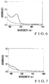
- Fig. 6 shows the absorption spectra of the sensor element of the second embodiment before and after the element was exposed to air to be measured.
- the broken line indicates the state before exposure.
- the solid line indicates the result after the sensor element of the second embodiment was exposed to air containing 300-ppb NO 2 , for three hours.
- the solid line has only one new absorption peak near 530 nm. It is considered that this absorption near 530 nm was caused by an azo dye produced when N,N-dimethylnaphthylamine coupled with a diazo compound as a diazotized form of sulfanilamide. The absorbance change was as high as about 0.1. It was also found that the sensor element of the second embodiment could perform highly sensitive detection of ppb-level nitrogen dioxide gas.
- the sensitivity index was calculated in the same manner as in the first embodiment.
- the calculated index was 1.3 x 10 -4 ppb -1 ⁇ hr -1 , i.e., very high sensitivity was obtained.
- Acetanilide (AA) as a diazotizing reagent and N,N-dimethylnaphthylamine (DMNA) as a coupling reagent were dissolved in a mixture solution of ethanol to prepare a sensing reagent solution.
- the concentration of acetanilide was 0.02 mol/l.
- the concentration of N,N-dimethylnaphthylamine was 0.005 mol/l.
- a porous body having an average pore-diameter of 4 nm was immersed in this sensing reagent solution.
- Vycor 7930 manufactured by Corning Glass Works was used as this porous body.
- the average pore-size of this Vycor 7930 was 4 nm.
- the chip dimensions of the porous body were 8 (mm) x 8 (mm) and a thickness of 1 (mm).
- This porous body was immersed in the sensing reagent solution for two hours. After the pores of the porous body were impregnated with the sensing reagent solution, the porous body was air-dried. Finally, the porous body was dried by leaving it in a nitrogen gas flow for a half day to manufacture a sensor element of this third embodiment.
- Fig. 7 shows the absorption spectra of the sensor element of the third embodiment before and after the element was exposed to air to be measured.
- the broken line indicates the state before exposure.
- the solid line indicates the result after the sensor element of the third embodiment was exposed to air containing 300-ppb NO 2, for three hours.
- the solid line has only one new absorption peak near 460 nm. Although this absorbance is about 0.03, highly sensitive ppb-level NO 2 detection is well possible.
- the sensitivity index was calculated in the same manner as in the first and second embodiments and found to be 3.3 x 10 -5 ppb -1 ⁇ hr -1 .
- This fourth embodiment relates to a nitrogen dioxide gas sensor using the sensor element described above.
- a light-emitting unit 801 which is an LED for emitting light having a predetermined wavelength emits light to a sensor element 802.
- a light-receiving unit 803 receives the transmitted light.
- the light-receiving unit 803 photoelectrically converts the received light and outputs a signal current.
- a conversion amplifier 804 amplifies the output signal current to perform current-voltage conversion.
- An A/D converter 805 converts the voltage signal into a digital signal.
- An output detector 806 outputs the digital signal as a detection result.
- the sensor element 802 is, e.g., the sensor element of the first embodiment described previously.
- the light-receiving unit 803 is, e.g., a photodiode. A light-emitting portion of the light-emitting unit 801 and a light-receiving portion of the light-receiving unit 803 oppose each other.
- a nitrogen dioxide gas sensor is realized with a simple arrangement.
- the fifth embodiment of the present invention will be described below.
- the above-mentioned nitrogen dioxide gas sensor will be described in more detail.
- the arrangements of the light-emitting unit and the light-receiving unit will be described.
- an LED 902 for emitting 550-nm green light and a phototransistor 903 are formed on a substrate 901 about 12 cm x 6 cm in size.
- the light-receiving surface of the phototransistor 903 opposes the light-emitting surface of the LED 902.
- This phototransistor has optical sensitivity in a wavelength region of 450 to 1,100 nm.
- Two AA cells 905 connected in series supply power to the LED 902 and the phototransistor 903 via a terminal plate 904. This power supply can be switched on and off by a switch 906. That is, a circuit is assembled by using terminals of the terminal plate 904.
- a line of the phototransistor 903 is connected to a terminal T1.
- a line of the switch 906 is connected to a terminal T2.
- a line of the LED 902 is connected to a terminal T3.
- a line of the cells 905 is connected to a terminal T4.
- Lines of the cells 905, the LED 902, and the phototransistor 903 are connected to a terminal T5.
- Resistors 907 and 908 are so connected that the phototransistor 903 outputs an order-of-magnitude voltage (V).
- a sensor element 910 as described in the first to third embodiments is inserted between the LED 902 and the phototransistor 903.
- a voltmeter is connected between the terminals T1 and T2 of the terminal plate 904 to measure the voltage.
- the nitrogen dioxide sensor measures nitrogen dioxide gas adsorbed by the sensor element 910.
- an accurate nitrogen dioxide gas sensor can be formed in an area of about 12 cm x 6 cm. Additionally, commercially available cells can be used as the power supply, so nitrogen dioxide gas can be sensed more simply.
- a mixture of a diazotizing reagent which reacts with nitrous ions to produce a diazo compound, a coupling reagent which couples with the diazo compound to produce an azo dye, and an acid is placed in pores of a transparent porous body to prepare a sensor element.
- the light transmittance of this sensor element is measured to calculate the first transmittance.
- the sensor element is then exposed to air to be measured for a predetermined time. After that, the light transmittance of the sensor element is measured to calculate the second transmittance. Nitrogen dioxide gas in the air to be measured is sensed in accordance with the difference between the first and second transmittances.
- the diazotizing reagent diazotizes nitrous ions produced by nitrogen dioxide adsorbed to pores of the sensor element to produce a diazo compound.
- the coupling reagent couples with this diazo compound to produce an azo dye. Consequently, the sensor element colors to make a difference between the first and second transmittances. This allows detection of the nitrogen dioxide gas.
- the nitrogen dioxide gas sensor element of the present invention comprises a transparent porous body, a diazotizing reagent placed in pores of the porous body to react with nitrous ions to produce a diazo compound, a coupling reagent placed together with the diazotizing reagent in the pores of the porous body to couple with the diazo compound to produce an azo dye, and an acid placed together with the diazotizing reagent in the pores of the porous body.
- the diazotizing reagent reacts with nitrous ions produced by the nitrogen dioxide gas to produce a diazo compound.
- the coupling reagent couples with this diazo compound to produce an azo dye. Consequently, the nitrogen dioxide gas sensor element colors.
- nitrogen dioxide gas can be sensed only by monitoring the color change of this nitrogen dioxide gas sensor element. So, nitrogen dioxide gas can be sensed more simply and accurately than in the conventional methods.
- the nitrogen dioxide gas sensor of the present invention comprises a light-emitting unit for emitting light, a light-sensing unit having a light-receiving surface opposed to a light-emitting surface of the light-emitting unit to output an electrical signal corresponding to a light amount received by the light-receiving surface, a sensor element inserted between the light-emitting unit and the light-sensing unit, and an electric meter for measuring the state of the output electrical signal from the light-sensing unit.
- the sensor element comprises a transparent porous body, a diazotizing reagent placed in pores of the porous body to react with nitrous ions to produce a diazo compound, a coupling reagent placed together with the diazotizing reagent in the pores of the porous body to couple with the diazo compound to produce an azo dye, and an acid placed together with the diazotizing reagent in the pores of the porous body.
- the diazotizing reagent reacts with nitrous ions produced by the nitrogen dioxide gas to produce a diazo compound.
- the coupling reagent couples with this diazo compound to produce an azo dye. Consequently, the nitrogen dioxide gas sensor element colors. Meanwhile, the light emitted from the light-emitting unit enters the light-sensing unit via the sensor element The electric meter measures the color change of the sensor element as a change in the output electrical signal from the light-sensing unit.
- this nitrogen dioxide gas sensor can accurately sense nitrogen dioxide gas when placed in an atmosphere to be measured. So, nitrogen dioxide gas can be sensed more simply and accurately than in the conventional methods.
Landscapes
- Chemical & Material Sciences (AREA)
- Life Sciences & Earth Sciences (AREA)
- Health & Medical Sciences (AREA)
- Physics & Mathematics (AREA)
- Biochemistry (AREA)
- General Physics & Mathematics (AREA)
- Pathology (AREA)
- Analytical Chemistry (AREA)
- Immunology (AREA)
- General Health & Medical Sciences (AREA)
- Dispersion Chemistry (AREA)
- Molecular Biology (AREA)
- Biophysics (AREA)
- Engineering & Computer Science (AREA)
- Chemical Kinetics & Catalysis (AREA)
- Plasma & Fusion (AREA)
- Investigating Or Analysing Materials By The Use Of Chemical Reactions (AREA)
- Investigating Or Analyzing Non-Biological Materials By The Use Of Chemical Means (AREA)
Applications Claiming Priority (6)
| Application Number | Priority Date | Filing Date | Title |
|---|---|---|---|
| JP23419397 | 1997-08-29 | ||
| JP234193/97 | 1997-08-29 | ||
| JP23419397 | 1997-08-29 | ||
| JP18450798 | 1998-06-30 | ||
| JP184507/98 | 1998-06-30 | ||
| JP18450798 | 1998-06-30 |
Publications (3)
| Publication Number | Publication Date |
|---|---|
| EP0901009A2 true EP0901009A2 (fr) | 1999-03-10 |
| EP0901009A3 EP0901009A3 (fr) | 1999-04-14 |
| EP0901009B1 EP0901009B1 (fr) | 2002-11-06 |
Family
ID=26502537
Family Applications (1)
| Application Number | Title | Priority Date | Filing Date |
|---|---|---|---|
| EP98250303A Expired - Lifetime EP0901009B1 (fr) | 1997-08-29 | 1998-08-27 | Procédé, élément de capteur, et capteur de gaz pour la détection du dioxyde d'azote |
Country Status (3)
| Country | Link |
|---|---|
| US (1) | US6362005B1 (fr) |
| EP (1) | EP0901009B1 (fr) |
| DE (1) | DE69809162T2 (fr) |
Cited By (2)
| Publication number | Priority date | Publication date | Assignee | Title |
|---|---|---|---|---|
| WO2012040032A3 (fr) * | 2010-09-23 | 2012-07-19 | 3M Innovative Properties Company | Indicateur chimique poreux pour milieux gazeux |
| EP2685241A4 (fr) * | 2011-03-11 | 2014-11-05 | Panasonic Healthcare Co Ltd | Dispositif de mesure de la concentration en oxydes d'azote |
Families Citing this family (6)
| Publication number | Priority date | Publication date | Assignee | Title |
|---|---|---|---|---|
| US7239766B2 (en) * | 2003-10-27 | 2007-07-03 | Mississippi State University | Optical sensing elements for nitrogen dioxide (NO2) gas detection, a sol-gel method for making the sensing elements and fiber optic sensors incorporating nitrogen dioxide gas optical sensing elements |
| EP2438432A4 (fr) * | 2009-06-05 | 2015-11-25 | Univ Arizona | Capteur optoélectrochimique intégré pour la détection des oxydes d'azote dans des échantillons gazeux |
| DE102009037706A1 (de) * | 2009-08-17 | 2011-02-24 | Opsolution Nanophotonics Gmbh | Verfahren und Vorrichtung zur Bestimmung der Konzentration von NO2 in Gasgemischen |
| FR2969295B1 (fr) * | 2010-12-16 | 2012-12-14 | Commissariat Energie Atomique | Detecteur multifonctionnel de composes gazeux et ses applications |
| JP7351462B2 (ja) * | 2019-11-15 | 2023-09-27 | 学校法人東北工業大学 | 一酸化窒素ガス検知方法及び一酸化窒素ガス検知装置 |
| CN113588876B (zh) * | 2021-07-13 | 2023-08-15 | 有研工程技术研究院有限公司 | 一种提高二氧化氮半导体传感器选择性的方法 |
Family Cites Families (18)
| Publication number | Priority date | Publication date | Assignee | Title |
|---|---|---|---|---|
| US2963351A (en) * | 1958-04-03 | 1960-12-06 | Mine Safety Appliances Co | Determination of nitrogen dioxide |
| US3512937A (en) * | 1967-06-06 | 1970-05-19 | Ferdinand Schulze | Procedure for continuous nitrogen dioxide analysis |
| US3681027A (en) * | 1971-05-28 | 1972-08-01 | Resource Control | Colorimetric indicator for the detection of nitrogen dioxide |
| BE787605A (fr) * | 1971-08-19 | 1973-02-16 | Merck Patent Gmbh | Agent de decelement de nitrites |
| JPS5815063B2 (ja) | 1979-02-03 | 1983-03-23 | 新日本製鐵株式会社 | 工場排水中微量硝酸イオン、亜硝酸イオンの自動分析方法 |
| JPS6012999A (ja) * | 1983-07-05 | 1985-01-23 | Fujisawa Pharmaceut Co Ltd | ス−パ−オキサイド基ならびにス−パ−オキサイドジスムタ−ゼ活性の測定法 |
| US4929561A (en) | 1985-08-08 | 1990-05-29 | Regents Of The University Of California | Absorption-emission optrode and methods of use thereof |
| JPH0623744B2 (ja) * | 1986-06-20 | 1994-03-30 | テルモ株式会社 | 亜硝酸塩検出用試験片 |
| WO1988005911A1 (fr) | 1987-02-04 | 1988-08-11 | Quantum Group, Inc. | Capteurs optiques de monoxyde de carbone appliques par impregnation sur des substrats monolithiques poreux |
| FR2613074B1 (fr) * | 1987-03-27 | 1990-06-08 | Commissariat Energie Atomique | Capteur chimique actif, a fibres optiques |
| DE3735176A1 (de) * | 1987-10-17 | 1989-04-27 | Draegerwerk Ag | Dosimeter |
| US5063164A (en) * | 1990-06-29 | 1991-11-05 | Quantum Group, Inc. | Biomimetic sensor that simulates human response to airborne toxins |
| JP2975768B2 (ja) | 1992-06-09 | 1999-11-10 | 松下電器産業株式会社 | スピロピラン担持体及びその製造方法 |
| JPH06300685A (ja) | 1993-04-16 | 1994-10-28 | Liquid Gas:Kk | ガス検知器 |
| US5618493A (en) * | 1994-08-29 | 1997-04-08 | Quantum Group, Inc. | Photon absorbing bioderived organometallic carbon monoxide sensors |
| US5573953A (en) * | 1994-09-09 | 1996-11-12 | Quantum Group, Inc. | Method for enhancing the response of a biomimetic sensor |
| WO1996014573A1 (fr) | 1994-11-07 | 1996-05-17 | Hoechst Aktiengesellschaft | Capteur polymere |
| JP3700877B2 (ja) | 1996-02-07 | 2005-09-28 | 日本電信電話株式会社 | 二酸化窒素ガス検出法および検出材料 |
-
1998
- 1998-08-24 US US09/139,066 patent/US6362005B1/en not_active Expired - Lifetime
- 1998-08-27 DE DE69809162T patent/DE69809162T2/de not_active Expired - Lifetime
- 1998-08-27 EP EP98250303A patent/EP0901009B1/fr not_active Expired - Lifetime
Cited By (5)
| Publication number | Priority date | Publication date | Assignee | Title |
|---|---|---|---|---|
| WO2012040032A3 (fr) * | 2010-09-23 | 2012-07-19 | 3M Innovative Properties Company | Indicateur chimique poreux pour milieux gazeux |
| CN103119436A (zh) * | 2010-09-23 | 2013-05-22 | 3M创新有限公司 | 用于气体介质的多孔化学指示物 |
| US9134251B2 (en) | 2010-09-23 | 2015-09-15 | 3M Innovative Properties Company | Porous chemical indicator for gaseous media |
| CN107064414A (zh) * | 2010-09-23 | 2017-08-18 | 3M创新有限公司 | 用于气体介质的多孔化学指示物 |
| EP2685241A4 (fr) * | 2011-03-11 | 2014-11-05 | Panasonic Healthcare Co Ltd | Dispositif de mesure de la concentration en oxydes d'azote |
Also Published As
| Publication number | Publication date |
|---|---|
| EP0901009B1 (fr) | 2002-11-06 |
| DE69809162D1 (de) | 2002-12-12 |
| US6362005B1 (en) | 2002-03-26 |
| EP0901009A3 (fr) | 1999-04-14 |
| DE69809162T2 (de) | 2003-07-24 |
Similar Documents
| Publication | Publication Date | Title |
|---|---|---|
| US7615192B2 (en) | Ozone gas measurement apparatus | |
| CA2552752C (fr) | Dispositif portatif a element jetable pour l'analyse chimique de plusieurs substances a analyser | |
| US7336362B2 (en) | Arsenic meter | |
| US6362005B1 (en) | Nitrogen dioxide gas sensing method, nitrogen dioxide gas sensor element, and nitrogen dioxide gas sensor using the same | |
| JP3639123B2 (ja) | 二酸化窒素ガスの検出方法および二酸化窒素ガスの検知素子およびそれを用いた二酸化窒素ガスの検出装置 | |
| CN102565040A (zh) | 便携式光电氨气检测装置 | |
| Hauser et al. | Optode for bulk-response membranes | |
| JP3700877B2 (ja) | 二酸化窒素ガス検出法および検出材料 | |
| Brandenburg et al. | Ammonia detection via integrated optical evanescent wave sensors | |
| JP3648105B2 (ja) | 二酸化窒素ガスの検出方法および二酸化窒素ガスの検出装置 | |
| Hochheiser | Methods of measuring and monitoring atmospheric sulfur dioxide | |
| JP7351462B2 (ja) | 一酸化窒素ガス検知方法及び一酸化窒素ガス検知装置 | |
| CN100460855C (zh) | 臭氧气体测量装置 | |
| CN214844785U (zh) | 一种溶解性有机物与硝态氮水质分析仪 | |
| JP2001141715A (ja) | 二酸化窒素ガスの検出装置 | |
| JP2001116738A (ja) | ガス濃度測定装置 | |
| CN2436934Y (zh) | 快速简便气体采集和测定装置 | |
| JP2001141714A (ja) | 二酸化窒素ガスの検出装置 | |
| Baldini | Recent progress in fiber optic pH sensing | |
| JPH0510618B2 (fr) | ||
| JP3589265B2 (ja) | 二酸化窒素ガス検知素子および検知方法および検知装置 | |
| CN121632969A (zh) | 一种基于选择性透过膜的原位荧光检测腔体、系统及方法 | |
| CN120064182A (zh) | 一种空气痕量三甲胺的高灵敏检测方法 | |
| Phillips et al. | INSTRUMENTATION FOR WATER QUALITY MEASUREMENTS | |
| Phillips et al. | Instruments for water quality measurements |
Legal Events
| Date | Code | Title | Description |
|---|---|---|---|
| PUAI | Public reference made under article 153(3) epc to a published international application that has entered the european phase |
Free format text: ORIGINAL CODE: 0009012 |
|
| PUAL | Search report despatched |
Free format text: ORIGINAL CODE: 0009013 |
|
| 17P | Request for examination filed |
Effective date: 19980925 |
|
| AK | Designated contracting states |
Kind code of ref document: A2 Designated state(s): AT BE CH CY DE DK ES FI FR GB GR IE IT LI LU MC NL PT SE |
|
| AX | Request for extension of the european patent |
Free format text: AL;LT;LV;MK;RO;SI |
|
| AK | Designated contracting states |
Kind code of ref document: A3 Designated state(s): AT BE CH CY DE DK ES FI FR GB GR IE IT LI LU MC NL PT SE |
|
| AX | Request for extension of the european patent |
Free format text: AL;LT;LV;MK;RO;SI |
|
| AKX | Designation fees paid |
Free format text: DE FR GB |
|
| 17Q | First examination report despatched |
Effective date: 20000320 |
|
| GRAG | Despatch of communication of intention to grant |
Free format text: ORIGINAL CODE: EPIDOS AGRA |
|
| GRAG | Despatch of communication of intention to grant |
Free format text: ORIGINAL CODE: EPIDOS AGRA |
|
| GRAG | Despatch of communication of intention to grant |
Free format text: ORIGINAL CODE: EPIDOS AGRA |
|
| GRAH | Despatch of communication of intention to grant a patent |
Free format text: ORIGINAL CODE: EPIDOS IGRA |
|
| GRAH | Despatch of communication of intention to grant a patent |
Free format text: ORIGINAL CODE: EPIDOS IGRA |
|
| GRAA | (expected) grant |
Free format text: ORIGINAL CODE: 0009210 |
|
| AK | Designated contracting states |
Kind code of ref document: B1 Designated state(s): DE FR GB |
|
| REG | Reference to a national code |
Ref country code: GB Ref legal event code: FG4D |
|
| REF | Corresponds to: |
Ref document number: 69809162 Country of ref document: DE Date of ref document: 20021212 |
|
| ET | Fr: translation filed | ||
| PLBE | No opposition filed within time limit |
Free format text: ORIGINAL CODE: 0009261 |
|
| STAA | Information on the status of an ep patent application or granted ep patent |
Free format text: STATUS: NO OPPOSITION FILED WITHIN TIME LIMIT |
|
| 26N | No opposition filed |
Effective date: 20030807 |
|
| REG | Reference to a national code |
Ref country code: FR Ref legal event code: PLFP Year of fee payment: 19 |
|
| REG | Reference to a national code |
Ref country code: FR Ref legal event code: PLFP Year of fee payment: 20 |
|
| PGFP | Annual fee paid to national office [announced via postgrant information from national office to epo] |
Ref country code: DE Payment date: 20170822 Year of fee payment: 20 Ref country code: GB Payment date: 20170822 Year of fee payment: 20 Ref country code: FR Payment date: 20170822 Year of fee payment: 20 |
|
| REG | Reference to a national code |
Ref country code: DE Ref legal event code: R071 Ref document number: 69809162 Country of ref document: DE |
|
| REG | Reference to a national code |
Ref country code: GB Ref legal event code: PE20 Expiry date: 20180826 |
|
| PG25 | Lapsed in a contracting state [announced via postgrant information from national office to epo] |
Ref country code: GB Free format text: LAPSE BECAUSE OF EXPIRATION OF PROTECTION Effective date: 20180826 |