EP0901236B1 - Générateur de code pseudo aléatoire - Google Patents
Générateur de code pseudo aléatoire Download PDFInfo
- Publication number
- EP0901236B1 EP0901236B1 EP19980116233 EP98116233A EP0901236B1 EP 0901236 B1 EP0901236 B1 EP 0901236B1 EP 19980116233 EP19980116233 EP 19980116233 EP 98116233 A EP98116233 A EP 98116233A EP 0901236 B1 EP0901236 B1 EP 0901236B1
- Authority
- EP
- European Patent Office
- Prior art keywords
- masking
- code
- code generating
- polynomial
- shift
- Prior art date
- Legal status (The legal status is an assumption and is not a legal conclusion. Google has not performed a legal analysis and makes no representation as to the accuracy of the status listed.)
- Expired - Lifetime
Links
Images


Classifications
-
- H—ELECTRICITY
- H04—ELECTRIC COMMUNICATION TECHNIQUE
- H04J—MULTIPLEX COMMUNICATION
- H04J13/00—Code division multiplex systems
- H04J13/0007—Code type
- H04J13/0022—PN, e.g. Kronecker
-
- G—PHYSICS
- G06—COMPUTING OR CALCULATING; COUNTING
- G06F—ELECTRIC DIGITAL DATA PROCESSING
- G06F7/00—Methods or arrangements for processing data by operating upon the order or content of the data handled
- G06F7/58—Random or pseudo-random number generators
- G06F7/582—Pseudo-random number generators
- G06F7/584—Pseudo-random number generators using finite field arithmetic, e.g. using a linear feedback shift register
-
- H—ELECTRICITY
- H03—ELECTRONIC CIRCUITRY
- H03K—PULSE TECHNIQUE
- H03K3/00—Circuits for generating electric pulses; Monostable, bistable or multistable circuits
- H03K3/84—Generating pulses having a predetermined statistical distribution of a parameter, e.g. random pulse generators
-
- H—ELECTRICITY
- H04—ELECTRIC COMMUNICATION TECHNIQUE
- H04J—MULTIPLEX COMMUNICATION
- H04J13/00—Code division multiplex systems
- H04J13/0074—Code shifting or hopping
-
- H—ELECTRICITY
- H04—ELECTRIC COMMUNICATION TECHNIQUE
- H04J—MULTIPLEX COMMUNICATION
- H04J13/00—Code division multiplex systems
- H04J13/10—Code generation
-
- Y—GENERAL TAGGING OF NEW TECHNOLOGICAL DEVELOPMENTS; GENERAL TAGGING OF CROSS-SECTIONAL TECHNOLOGIES SPANNING OVER SEVERAL SECTIONS OF THE IPC; TECHNICAL SUBJECTS COVERED BY FORMER USPC CROSS-REFERENCE ART COLLECTIONS [XRACs] AND DIGESTS
- Y02—TECHNOLOGIES OR APPLICATIONS FOR MITIGATION OR ADAPTATION AGAINST CLIMATE CHANGE
- Y02D—CLIMATE CHANGE MITIGATION TECHNOLOGIES IN INFORMATION AND COMMUNICATION TECHNOLOGIES [ICT], I.E. INFORMATION AND COMMUNICATION TECHNOLOGIES AIMING AT THE REDUCTION OF THEIR OWN ENERGY USE
- Y02D30/00—Reducing energy consumption in communication networks
- Y02D30/70—Reducing energy consumption in communication networks in wireless communication networks
Definitions
- the present invention relates to a PN code generating apparatus applicable to a mobile device in a mobile communication system in which an intermittent reception is performed, for instance a CDMA (Code Division Multiple Access) communication system, and to a mobile radio communication system.
- a PN code generating apparatus applicable to a mobile device in a mobile communication system in which an intermittent reception is performed, for instance a CDMA (Code Division Multiple Access) communication system, and to a mobile radio communication system.
- CDMA Code Division Multiple Access
- transmission data are specturm spread with a spreading code that is different each channel.
- a spreading code that is different each channel.
- IS-95-A includes a short PN code of 15th order (the period is about 26ms) and a long PN code of 42th order (the period is about 41 days) consumed in spectrum spreading.
- the long PN code is also used in the scramble for a forward link and in the assigning of an insert position of power control bit.
- FIG.1 illustrates a schematic configuration of a conventional PN code generating apparatus.
- PN code generating section 100 comprises a feedback shift register composed of 41 EX-ORs (EXclusive-OR circuit) 101, 42 one-clock-delay elements 102, 42 primitive polynomial coefficients 103 and 42 multipliers 104.
- the initial values of delay elements are set so that all values are not 0 at the same time, and the value of delay element 102 is shifted corresponding to an input of shift clock 105 considering the feedback of the value of the last slot.
- Any output of delay element is obtained as a PN code.
- a mobile device sets the initial value of delay element 102 at a system timing in the process of the synchronization acquisition with a base station, then generates a PN code using a chip rate consumed in spreading in a CDMA system as a shift clock.
- a mobile device in a mobile communication system performs the monitoring reception to check a call once in the specific period predetermined with a base station while waiting. This is called an intermittent reception, in which as many circuits as possible except a timer for measuring a timing for the next monitoring reception are turned off during the non-reception period so as to reduce the consumed electric power.
- the present invention is carried out taking into account the above facts.
- the object of the present invention is to provide a PN code generating apparatus and method capable of acquiring the synchronization of long PN code immediately when the apparatus is restart after the stop state in an intermittent reception.
- the first aspect of the present invention adopts the constitution comprising a PN code generating section for generating PN code has predetermined length using primitive polynomial G(x), then shifting the code content , and a state setting section for obtaining a code state of the PN code generating section after shifted the specific times from a code state of the PN code generating apparatus at a certain time, based on x i modG (x) as the number of shifts is i.
- First x i modG(x) is calculated or obtained in advance where i is the number of shifts that should be necessary for a PN code generating apparatus in the case where it is assumed to be operating during the period from the turn-off to the next turn-on.
- the state at which the PN code generating apparatus is supposed to be when the next turn-on is obtained using x i modG(x), which indicates only the number of the shifts corresponding to the length of a PN code (42 shifts in this example) is enough to obtain the state of a PN code generating apparatus (the content of delay element) just after turned on using the state of the PN code generating apparatus (the content of delay element) just before turned off.
- the second aspect of the present invention comprises a masking calculating section for acquiring the number of shifts: i corresponding to a period until a PN code generating apparatus restarts next to calculate x i modG(x).
- the third aspect of the present invention comprises a masking table in which a plurality of x i modG(x) obtained to a plurality of the number of shifts selected in advance are registered as a masking value, and a masking setting section for reading out the masking value from the masking table based on a value of n to obtain a status of a PN code generating apparatus after n*T time (n is an integer number) where the minimum period to calculate the target state of a PN code generating apparatus is T.
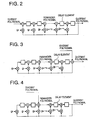
- a cyclic code (n,k) (n: code length, k: information bit length) is obtained as a remainder when M(x)x n-k is divided by G(x), where a polynomial with a information bit as a efficient is represented as M(x) of (k-1)th order, and a generation polynomial is represented G(x) of (n-k)th order, which is shown in the following formulation.
- M x x n - k Q x ⁇ G x + R x
- R(x)of(n-k-1)th order is a remainder polynomial to give a redundancy bit.
- Formulation (1) is transformed as shown below.
- M x x n - k - R x Q x ⁇ G x That results in a code word M(x) x n-k - R(x) that can be divided by G(x) without a remainder.
- (n-k) bits of 0 should be inputted in the configuration in FIG.2, which is modified to the configuration in illustrated in FIG.3.
- to input k bits from the coefficients with higher orders of M(x) is enough to obtain a remainder corresponding to a coefficient in m numbers of delay elements in the feedback shift register.
- This configuration results in the equivalent to multiply x n-k automatically by modifying an input position of a coefficient of divided polynomial from the least order to the highest order of a generation polynomial.
- a cyclic code is calculated using a feedback register configured as illustrated in FIG.3.
- FIG.3 illustrates a circuit to obtain a remainder of polynomial M(x) x n-k .
- a circuit to obtain a remainder of polynomial M(x) x 2 is as illustrated in FIG.4. That is, in the case of obtaining a remainder of polynomial M(x) x i (i ⁇ m), an input is executed to an EX-OR (Exclusive OR circuit) corresponding to i order in the feedback shift register.
- EX-OR Exclusive OR circuit
- Formulation (3) is obtained by replacing n-k in formulation (1) with i.
- M x x i Q x ⁇ G x + R x
- Formulation (3) is also expressed in another formulation below.
- R x M ( x ) x i mod G x
- formulation (4) is transformed as shown below.
- R x M ( x ) x i modG x modG x
- R x M ( x ) S x modG x
- S(x) x i modG (x) and S(x) is a polynomial of less than m-1 order.
- the technical subject to obtain the state of a PN code generator (the contents of shift register) after shifted the specific times from the state of the PN code generator at a certain time without the number of shifts is solved by applying the above principle.
- a primitive (generator) polynomial of a PN code generator is G(x)(m order) and the state of the PN code generator at a certain time is M(x)(m order).
- the configuration of a PN code generator is composed of a configuration illustrated in FIG.2 except an input of a divident polynomial, expediently a PN code generator with the input is assumed.
- the content of each shift register is 0 after cleared. That state is changed to the state of a PN code generator at a certain time after sequentially inputting m bits from a coefficient with the highest order in M(x) to a left input.
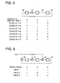
- FIG.5 illustrates a configuration and the changes of state during a bit is shifting from the state at a certain time; t of a PN code generator.
- An explanation is given to obtain the state after five shifts from starting the state at a certain time; t, using the above-mentioned principle.
- First is to obtain x i mod G(x).
- 1, 0 and 0 according to this order are inputted in the configuration illustrated in FIG. 6.
- the last state illustrated in FIG.6 is obviously the same as the state at t+5 in FIG.5.
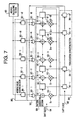
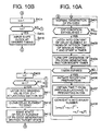
- FIG.7 is a diagram illustrating a schematic configuration of a PN code generating apparatus in the first embodiment of the present invention.
- a PN code generating apparatus in this embodiment comprises PN code generating section 100 for generating PN code of 42 stages, parallel/serial converting section 200 for parallel/serial converting the content of a delay element of PN code generating section 100, masking value holding section 300 for holding a masking value, masking calculating section 400 for calculating a masking value which is to be hold in masking value holding section 300, AND block 500 for calculating AND of an output in masking value holding section 300 and an output in parallel/serial section 200.
- PN code generating section 100 42 EX-ORs 101-1 up to 101-42 are serial connected, and 42 delay elements 102-1 up to 102-42 are serial inserted after an output of EX-ORs 101-1 up to 101-42 respectively.
- 42 multipliers 103-1 up to 103-42 are prepared respectively corresponding to EX-ORs 101-1 up to 101-42.
- Each of multipliers 103-1 up to 103-42 multiplies respectively each of primitive polynomial coefficients g0 up to g41 and an output in the last delay element 102-42 to output a multiplied value to each EX-ORs 101-1 up to 101-42 respectively.
- a feedback register is composed of 42 EX-ORs 101-1 up to 101-42, 42 delay elements 102-1 up to 102-42 and 42 multipliers 103-1 up to 103-42 in which 42 primitive polynomial coefficients are respectively multiplied.
- the initial value setting is executed so that initial values of delay elements 102-1 up to 102-42 are not all 0 at the same time.
- the value of delay element is shifted each input of shift clock 104 considering the feedback of the last stage value.
- a PN code is obtained by fetching an output of any delay element.
- Parallel/serial converting section 200 is composed of 42 serial connected latching sections 201-1 up to 201-42. Latching sections 201-1 up to 201-42 respectively latches into the content of delay elements, and transfer the latched content to a neighboring latter latching section. In other word, parallel/serial converting section 200 latches into the PN code of 42 stages parallel inputted from PN code generating section so as to serial output working as a shift register.
- Masking value holding section 300 is composed of 42 latching sections 301-1 up to 301-42 each prepared corresponding to each EX-ORs 101-1 up to 101-42 in PN code generating section. Latching sections 301-1 up to 301-42 are to latch into the masking value calculated in masking calculating section 400.
- Masking calculating section 400 obtains the number of shift times which is the required number of shift times in PN code generating section 100 to calculate the state (the content of delay element 102) of PN code generating section 100 at the specific time after the state (the content of delay element 102) of PN code generating section 100 at a certain time.
- AND block 500 is composed of 42 AND gates 501-1 up to 501-42 each prepared between each of latching sections 301-1 up to 301-42 in masking value holding section 300 and each of EX-ORs 101-1 up to 101-42 in PN code generating section 100.
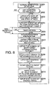
- PN code generating section 100 is executing the normal code generation (S201).
- S202 latching sections 201-1 up to 201-42 each latches into each content of delay elements 102-1 up to 102-42 respectively, and the internal timer starts concurrently (S203). And the operation in PN code generating section 100 except the timer is turned off (S204).
- a receiving preparation is initiated (S206).
- the time set in the timer is a little shorter time than next monitor receiving timing, including an estimated time for the process that masking calculating section 400 calculates a mask value.
- the receiving preparation As the receiving preparation is initiated, first the period time between from previously latching sections 201-1 up to 201-42 latched into the content of PN code generating section 100 to restart PN code generation section 100 is obtained (S207). Next the number of shift times in code generating section corresponding to this period time until restarting is obtained, and the obtained number of shift times is assigned as i (S208). Then masking calculating section 400 calculates x i modG(x) to obtain a masking value (S209).
- Each of latching sections 301-1 up to 301-42 in masking value holding section 300 holds the masking values calculated in masking calculating section 400 (S210).
- Next delay elements 102-1 up to 102-42 in PN code generating section 100 are cleared to 0 (S211).
- shift clock 104 is inputted at the desired timing corresponding to the number of shifts (i), and the generation of PN code is initiated in PN code generating section 100 (S213).
- the minimum non-reception period is 1.28s, and a used shift clock is 1.2288 MHz.
- a used shift clock is 1.2288 MHz.
- a period time until restarting is obtained at step S206.
- the number of shift times during a period to restart is already known.
- the number of shift times is acquired in advance directly, like this case, it is not necessary to always calculate the period.
- a PN code generating apparatus in the second embodiment of the present invention comprises masking value table 601 in which a plurality of pre-calculated masking values are stored, and masking setting instructing section 602 for selecting a masking value in mask table 601 to be used, instead of masking calculating section 400 in the first embodiment of the present invention.
- FIG.9 illustrates a diagram of a schematic configuration of a PN code generating apparatus in the second embodiment of the present invention.
- 100 denotes a PN code generating section 100 that is the same as a conventional one
- the feedback register is composed of 42 EX-OR 101-1 up to 101-42, delay elements 102-1 up to 102-42 and multiplier 103-1 up to 103-42 for multiplying 42 primitive polynomial coefficients g0 up to g41.
- 200 denotes a parallel/serial converting section, which is composed of latching section 201-1 up to 201-42 each for latching into each of content of delay elements 102-1 up to 1-2-42 in PN code generating section 100.
- 300 denotes a masking holding section, and 500 denotes AND block.
- masking table 601 pre-calculated masking values, for instance, for 2 i ⁇ T(i>0) are registered, as T is the minimum period to obtain the state of PN code generating section 100 by calculating.
- Masking setting instructing section 602 controls a masking value read from masking table 601 based on the value of n, to calculate the state of PN code generating section 100 (the content of delay elements) n ⁇ T time (n is an integral number) after the state of PN code generating section 100 (the content of delay elements) at a certain time.
- PN code generating section 100 is executing the normal code generation (S401).
- latching sections 201-1 up to 201-42 each latches each content of delay element 102-1 up to 102-42 respectively at a timing so that a period time until restarting is an integer times of the minimum period time T, and an internal timer starts concurrently (S403).
- the operation in PN code generating section 100 except the timer is turned off (S404).
- the time set in the timer is a little shorter time than next monitor receiving timing, which is the same as the first embodiment.
- masking setting instructing section 602 obtains the period time until restarting PN code generation section 100 from previously latching sections 201-1 up to 201-42 latched into the content of PN code generating section 100 as n ⁇ T (n is an integral number)(S407).
- masking setting instructing section 602 reads out a masking value for predetermined 2 j ⁇ T from masking value table 601 to hold latching section 301-1 up to 301-42 in masking holding section 300 (S411).
- delay element 102-1 up to 102-42 in PN code generating section 100 are cleared to 0 (S412), using latching section 201-1 up to 201-42 in parallel/serial converting section 200 having the latched contents of delay element 102-1 up to 102-42 that is equivalent to the previous state of PN code generating section 100 as a shift register, the number of clocks corresponding to the number of stages for a PN code (in this case, 42 clocks) are inputted as shift clock 202 and shift clock 104 to PN code generating section 100, the target state of PN code generating section 100 is obtained (S413).
- step S409 the processing from step S409 to step S414 described above is repeated.
- shift clock 104 is inputted at the desired timing corresponding to the number of shift times (i), and the generation of PN code is initiated in PN code generating section 100 (S416).
- the state of a PN code generator after shifted the specific times from the state of a PN code generator (the content of a shift register) at a certain time with less number of shift times than the specific number of shift times, which enables to turn off a PN code generating section during a non-reception period in an intermittent reception system.
- x i modG(x) is calculated based on the number of shift times, however when the value of i is very large, x i modG(x) is not calculated on real time.
- the non-reception period is set at the integer times of the minimum time period T, for instance, it is assumed 2 i *T (i>0).
- masking values for 2 i *T period are pre-calculated to register in a masking table, and the states of a PN code generating section are sequentially calculated using a plurality of the masking values. According to the processes described above, the final target state of the PN code generating section is obtained.
- PN code generating section 100 is composed of a feedback shift register that is hardware to calculate the state of PN code generating section 100. It is also preferable to achieve the same processing functions as those of PN code generating section and peripheral circuits with a processor such as CPU and DSP in software.
- a PN code generating apparatus in the first embodiment or the second embodiment of the present invention in a mobile station apparatus in a mobile radio communication system, it is possible to reduce the power consumption the mobile station apparatus in the intermittent reception. And it is also preferable to install a PN code generating apparatus of the present invention in a base station apparatus in a mobile radio communication system. Further in the case of an information portable terminal for the radio communication in a CDMA system, it is possible to reduce the consumed electric power by comprising a PN code generating apparatus. It is also preferable to incorporate a PN code generating apparatus of the present invention into LSI or a circuit (or print board).
Landscapes
- Engineering & Computer Science (AREA)
- Computer Networks & Wireless Communication (AREA)
- Signal Processing (AREA)
- Physics & Mathematics (AREA)
- Theoretical Computer Science (AREA)
- General Physics & Mathematics (AREA)
- Mathematical Analysis (AREA)
- Mathematical Optimization (AREA)
- Pure & Applied Mathematics (AREA)
- General Engineering & Computer Science (AREA)
- Computational Mathematics (AREA)
- Synchronisation In Digital Transmission Systems (AREA)
- Mobile Radio Communication Systems (AREA)
- Error Detection And Correction (AREA)
Claims (10)
- Appareil de génération de code PN comprenant,
un registre à décalage (100) pour générer un code PN, ledit registre à décalage (100) ayant une pluralité d'éléments à retard connectés en série (102-1 à 102-42) où le nombre desdits éléments à retard (102-1 à 102-42) est en correspondance avec le nombre d'ordres d'un polynôme primitif G (x), une pluralité de OU exclusifs (101-1 à 101-42) chacun préparé à un étage d'entrée de chacun desdits éléments à retard (102-1 à 102-42), et un moyen de multiplication (103-1 à 103-42) pour multiplier un code de rétroaction sorti depuis un élément à retard prédéterminé (102-42) par un coefficient (g0- g41) de chaque ordre dudit polynôme primitif G(x) de manière à faire entrer chaque valeur multipliée à un OU exclusif (101-1 à 101-42) correspondant à chaque ordre respectivement ; et
un moyen de masquage (300, 400) pour générer un masque multi-bits ;
caractérisé en ce que
ledit moyen de masquage (300, 400) étant adapté pour générer un polynôme de masquage S(x) sur la base de la formulation suivante ;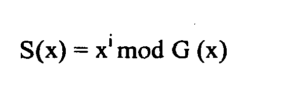
où i est le nombre de fois de décalages auquel ledit registre à décalage (100) doit être décalé pendant une certaine période à partir d'un premier temps jusqu'à un deuxième temps ; et comprenant en plus
un moyen d'établissement d'état (200, 500) qui inclut :un moyen de conversion parallèle/série (200) pour faire sortir en série une pluralité de données binaires sauvegardées en parallèle, tout en sauvegardant en parallèle des données binaires de mémoire dudit chaque élément à retard (102-1 à 102-42) indiquant un état dudit registre à décalage (100) audit premier temps ; etune pluralité de ET (500) préparés correspondant à chacun desdits OU exclusifs (101-1 à 101-42) pour calculer un produit logique de données binaires sorties depuis ledit moyen de conversion parallèle/série (200) et le chaque ordre dudit S(x) pour entrer le produit logique à un OU exclusif correspondant (101-1 à 101-42). - Appareil de génération de code selon la revendication 1, dans lequel ledit moyen de masquage (400) calcule le nombre de fois de décalages "i" auquel ledit registre à décalage doit être décalé pendant une période à partir de l'achèvement d'une opération d'une génération de code PN jusqu'à un redémarrage de l'opération.
- Appareil de génération de code PN selon la revendication 1, dans lequel ledit moyen de masquage (300, 400) maintient à l'avance le nombre de fois de décalages "i" auquel ledit registre à décalage (100) doit être décalé pendant une période à partir de l'achèvement d'une opération d'une génération de code PN jusqu'à un redémarrage de l'opération.
- Appareil de génération de code PN selon la revendication 1, dans lequel ledit moyen de masquage (600) comprenant en plus :un moyen de sauvegarde (601) pour sauvegarder une pluralité de polynômes de masquage S(x) précalculés correspondant à une pluralité du nombre de fois de décalages "i" ou une information concernant chaque ordre du polynôme de masquage S(x) ; et un moyen de sélection (602) pour sélectionner un polynôme de masquage S(x) ou une information concernant chaque ordre du polynôme de masquage à partir dudit moyen de sauveagarde (601).
- Appareil de génération de code PN selon la revendication 1, dans lequel ledit moyen de masquage (600) comprenant en plus :un moyen de sauvegarde (601) pour sauvegarder une pluralité de polynômes de masquage S(x) précalculés correspondant à une pluralité du nombre de fois de décalages "i" ou une information concernant chaque ordre du polynôme de masquage S(x) ; et un moyen de sélection (602) pour sélectionner un polynôme de masquage S(x) ou une information concernant le chaque ordre du polynôme de masquage à partir dudit moyen de sauvegarde (601) sur la base d'une valeur de n comme nxT (n est un nombre entier et T est une unité temporelle) est une période de temps à partir du premier temps jusqu'au deuxième temps.
- Appareil de génération de code PN selon la revendication 5, dans lequel ledit moyen de sélection (602) sélectionne un S(x) correspondant à m < i > xT ou une information concernant un ordre du S(x) en augmentant séquentiellement une valeur de i comme n = m< i >.
- Appareil de station mobile pour établir une communication radio avec une station de base dans un système CDMA, ledit appareil de station mobile comprend un appareil de génération de code PN selon la revendication 1.
- Appareil de station de base pour établir une communication radio avec un appareil de station mobile, ledit appareil de station de base comprend l'appareil de génération de code PN selon la revendication 1.
- Procédé de génération d'un code PN en utilisant un registre à décalage (100), dans lequel ledit registre à décalage (100) a une pluralité d'éléments à retard connectés en série (102-1 à 102-42) où le nombre desdits éléments à retard (102-1 à 102-42) correspondant à l'ordre d'un polynôme primitif G(x), une pluralité de OU exclusifs (101-1 à 101-42) chacun préparé à un étage d'entrée de chacun desdits éléments à retard (102-1 à 102-42), et un moyen de multiplication (103-1 à 103-42) pour multiplier un code de rétroaction sorti depuis un élément à retard prédéterminé (102-1 à 102-42) par un coefficient de chaque ordre dudit polynôme primitif G(x) de manière à entrer chaque valeur multipliée à un OU exclusif correspondant à chaque ordre,
caractérisé par
ledit procédé comprenant les étapes consistant à :générer un polynôme de masquage S(x) sur la base de la formulation suivante ;où i est le nombre de fois de décalages auquel ledit registre à décalage (100) doit être décalé pendant une certaine période à partir d'un premier temps jusqu'à un deuxième temps ; et
verrouiller (S203) des données de chaque élément à retard (102-1 à 102-42) lorsqu'il est jugé (S204) que la condition prédéterminée est établie pour éteindre la section de génération de code PN (registre à décalage 100),
démarrer une minuterie interne (S203) de manière simultanée,
obtenir la période de temps (S207) entre le verrouillage précédent (S203) et l'opération de redémarrage,
obtenir le nombre des fois de décalages (S208) pendant la période de temps obtenue et attribuer i au nombre de fois de décalages obtenu ;
calculer x' mod G(x) afin d'obtenir une valeur de masquage (S209) ;
maintenir la valeur de masquage calculée (S210) et remettre les éléments à retard (S211) à zéro ;
utiliser les donnés verrouillées qui sont équivalentes à l'état précédent (audit premier temps) de la section de génération de code PN, obtenir (S212) l'état cible (audit deuxième temps) de la section de génération de code PN en entrant l'horloge de décalage ; et
entrer l'horloge de décalage au minutage désiré (S213) lorsque l'état de la section de génération de code PN atteint l'état après avoir effectué un décalage du nombre de fois spécifique (i). - Programme d'ordinateur pour exploiter un ordinateur, ledit programme d'ordinateur comprenant :un support lisible par ordinateur ;un premier moyen d'instruction de programme pour donner instruction à un processeur d'ordinateur pour décaler une pluralité de données binaires formant un code à un étage suivant selon une horloge de décalage, et pour multiplier un coefficient de chaque ordre d'un polynôme primitif G(x) par des données binaires auxquelles l'ordre correspond des ordres spécifiques dans ledit code de manière à générer un nouveau code ; etcaractérisé par
un deuxième moyen d'instruction de programme pour donner instruction à un processeur d'ordinateur pour exécuter les étapes du procédé tel que défini dans la revendication 9 ;
et dans lequel chacun dudit moyen d'instruction de programme est enregistré sur ledit support sous une forme exécutable et est chargeable dans une mémoire d'ordinateur pour une exécution par le processeur associé.
Priority Applications (1)
| Application Number | Priority Date | Filing Date | Title |
|---|---|---|---|
| EP07108762.1A EP1835617B1 (fr) | 1997-09-02 | 1998-08-27 | Appareil et procédé de génération de code pseudo aléatoire |
Applications Claiming Priority (3)
| Application Number | Priority Date | Filing Date | Title |
|---|---|---|---|
| JP25287297 | 1997-09-02 | ||
| JP252872/97 | 1997-09-02 | ||
| JP25287297A JP3329705B2 (ja) | 1997-09-02 | 1997-09-02 | Pn符号発生装置及び移動無線通信システム |
Related Child Applications (1)
| Application Number | Title | Priority Date | Filing Date |
|---|---|---|---|
| EP07108762.1A Division EP1835617B1 (fr) | 1997-09-02 | 1998-08-27 | Appareil et procédé de génération de code pseudo aléatoire |
Publications (3)
| Publication Number | Publication Date |
|---|---|
| EP0901236A2 EP0901236A2 (fr) | 1999-03-10 |
| EP0901236A3 EP0901236A3 (fr) | 2002-03-13 |
| EP0901236B1 true EP0901236B1 (fr) | 2007-10-17 |
Family
ID=17243347
Family Applications (2)
| Application Number | Title | Priority Date | Filing Date |
|---|---|---|---|
| EP19980116233 Expired - Lifetime EP0901236B1 (fr) | 1997-09-02 | 1998-08-27 | Générateur de code pseudo aléatoire |
| EP07108762.1A Expired - Lifetime EP1835617B1 (fr) | 1997-09-02 | 1998-08-27 | Appareil et procédé de génération de code pseudo aléatoire |
Family Applications After (1)
| Application Number | Title | Priority Date | Filing Date |
|---|---|---|---|
| EP07108762.1A Expired - Lifetime EP1835617B1 (fr) | 1997-09-02 | 1998-08-27 | Appareil et procédé de génération de code pseudo aléatoire |
Country Status (7)
| Country | Link |
|---|---|
| US (2) | US6295301B1 (fr) |
| EP (2) | EP0901236B1 (fr) |
| JP (1) | JP3329705B2 (fr) |
| KR (1) | KR100280025B1 (fr) |
| CN (2) | CN100379299C (fr) |
| CA (1) | CA2246168C (fr) |
| DE (1) | DE69838572T2 (fr) |
Families Citing this family (21)
| Publication number | Priority date | Publication date | Assignee | Title |
|---|---|---|---|---|
| JP3329705B2 (ja) * | 1997-09-02 | 2002-09-30 | 松下電器産業株式会社 | Pn符号発生装置及び移動無線通信システム |
| KR100509471B1 (ko) * | 1998-07-24 | 2005-10-26 | 삼성전자주식회사 | 개선된 pn 코드 생성기 |
| JP4027520B2 (ja) * | 1998-12-24 | 2007-12-26 | 富士通株式会社 | コード位相設定方法及び装置 |
| KR20000066904A (ko) * | 1999-04-21 | 2000-11-15 | 윤종용 | 부호분할다중접속 통신시스템의 확산코드 발생장치 및 방법 |
| KR100429545B1 (ko) | 1999-08-17 | 2004-04-28 | 삼성전자주식회사 | 이동통신 시스템의 스크램블링 부호의 식별자 통신방법 |
| JP3274668B2 (ja) | 1999-10-18 | 2002-04-15 | 松下電器産業株式会社 | 演算処理装置及び演算処理方法 |
| US6526427B1 (en) | 1999-12-06 | 2003-02-25 | D.S.P.C. Technologies Ltd. | Method of mask calculation for generation of shifted pseudo-noise (PN) sequence |
| WO2001050239A1 (fr) * | 1999-12-30 | 2001-07-12 | Morphics Technology, Inc. | Appareil et procede de calcul et d'installation d'un masque de fibonacci conçu pour un generateur de codes |
| KR100805343B1 (ko) * | 2000-11-15 | 2008-02-20 | 인도오스트 인베스트먼츠 피티와이 엘티디 | 시프트 레지스터의 업데이트 방법 |
| KR100396592B1 (ko) * | 2001-05-02 | 2003-09-02 | 엘지전자 주식회사 | 시간 천이된 pn 스테이트 발생기 |
| US20030043938A1 (en) * | 2001-08-28 | 2003-03-06 | Optix Networks Inc. | Apparatus and method for periodic pattern detection |
| KR20030072461A (ko) * | 2002-03-04 | 2003-09-15 | (주) 윌텍정보통신 | Cdma 시스템에서의 롱코드 상태값 계산 장치 |
| US7398287B2 (en) * | 2002-08-19 | 2008-07-08 | Analog Devices, Inc. | Fast linear feedback shift register engine |
| JP2006075233A (ja) * | 2004-09-07 | 2006-03-23 | Terumo Corp | 血管内異物除去用ワイヤおよび医療器具 |
| CN1787415B (zh) * | 2004-12-08 | 2011-05-25 | 中兴通讯股份有限公司 | 实现伪随机码相位偏移的装置及其生成伪随机码的方法 |
| US7991040B2 (en) * | 2006-04-04 | 2011-08-02 | Qualcomm Incorporated | Methods and apparatus for reduction of a peak to average ratio for an OFDM transmit signal |
| US7487194B2 (en) * | 2006-04-05 | 2009-02-03 | Peter Lablans | Binary and n-valued LFSR and LFCSR based scramblers, descramblers, sequence generators and detectors in Galois configuration |
| US8345873B2 (en) * | 2007-04-04 | 2013-01-01 | Ternarylogic Llc | Methods and systems for N-state signal processing with binary devices |
| CN101478361B (zh) * | 2008-11-25 | 2012-07-04 | 南京师范大学 | 一种多维类正交伪随机矩阵的构成装置 |
| CN102723965B (zh) * | 2012-06-19 | 2014-06-25 | 哈尔滨工程大学 | Pn码串并组合联接的扩频通信方法 |
| JP2014222394A (ja) * | 2013-05-13 | 2014-11-27 | 株式会社東芝 | 半導体記憶装置および乱数発生器 |
Citations (1)
| Publication number | Priority date | Publication date | Assignee | Title |
|---|---|---|---|---|
| US5596571A (en) * | 1994-01-05 | 1997-01-21 | Nokia Mobile Phones Ltd. | CDMA radiotelephone having optimized slotted mode and long code operation |
Family Cites Families (15)
| Publication number | Priority date | Publication date | Assignee | Title |
|---|---|---|---|---|
| GB1190809A (en) * | 1967-06-26 | 1970-05-06 | Ericsson Telefon Ab L M | Improvements in and relating to the Generation of a Pulse Code |
| US3742381A (en) * | 1971-06-09 | 1973-06-26 | California Inst Of Techn | Wideband digital pseudo gaussian noise generator |
| JPS60220635A (ja) * | 1984-04-17 | 1985-11-05 | Clarion Co Ltd | スペクトラム拡散送受信機 |
| US5031129A (en) * | 1989-05-12 | 1991-07-09 | Alcatel Na Network Systems Corp. | Parallel pseudo-random generator for emulating a serial pseudo-random generator and method for carrying out same |
| AU660357B2 (en) * | 1992-03-23 | 1995-06-22 | Sharp Kabushiki Kaisha | Spread spectrum communication system and an apparatus for communication |
| US5228054A (en) * | 1992-04-03 | 1993-07-13 | Qualcomm Incorporated | Power-of-two length pseudo-noise sequence generator with fast offset adjustment |
| JP2600580B2 (ja) * | 1993-09-09 | 1997-04-16 | 日本電気株式会社 | 同期式pn符号系列発生回路 |
| JP2734956B2 (ja) | 1993-12-24 | 1998-04-02 | 日本電気株式会社 | スペクトラム拡散用pn符号同期方法 |
| ZA95797B (en) * | 1994-02-14 | 1996-06-20 | Qualcomm Inc | Dynamic sectorization in a spread spectrum communication system |
| KR970002951B1 (ko) * | 1994-04-13 | 1997-03-13 | 양승택 | 2^n길이 의사 난수 계열 발생 장치 |
| JPH0818550A (ja) | 1994-04-27 | 1996-01-19 | N T T Ido Tsushinmo Kk | 符号系列発生器 |
| US5568473A (en) * | 1994-12-08 | 1996-10-22 | Comsat Corporation | Method and apparatus for simple and efficient interference cancellation for chip synchronized CDMA |
| CN1097894C (zh) * | 1995-05-12 | 2003-01-01 | 皇家菲利浦电子有限公司 | 直接序列扩频通信系统,解扩方法及无线主站和无线从站 |
| JP3372135B2 (ja) | 1995-05-24 | 2003-01-27 | ソニー株式会社 | 通信端末装置 |
| JP3329705B2 (ja) * | 1997-09-02 | 2002-09-30 | 松下電器産業株式会社 | Pn符号発生装置及び移動無線通信システム |
-
1997
- 1997-09-02 JP JP25287297A patent/JP3329705B2/ja not_active Expired - Lifetime
-
1998
- 1998-08-25 US US09/139,325 patent/US6295301B1/en not_active Expired - Lifetime
- 1998-08-27 CN CNB021273650A patent/CN100379299C/zh not_active Expired - Lifetime
- 1998-08-27 DE DE1998638572 patent/DE69838572T2/de not_active Expired - Lifetime
- 1998-08-27 CN CN98118564A patent/CN1094019C/zh not_active Expired - Lifetime
- 1998-08-27 EP EP19980116233 patent/EP0901236B1/fr not_active Expired - Lifetime
- 1998-08-27 EP EP07108762.1A patent/EP1835617B1/fr not_active Expired - Lifetime
- 1998-08-31 CA CA 2246168 patent/CA2246168C/fr not_active Expired - Lifetime
- 1998-09-01 KR KR1019980035898A patent/KR100280025B1/ko not_active Expired - Fee Related
-
2001
- 2001-07-30 US US09/916,284 patent/US6697384B2/en not_active Expired - Lifetime
Patent Citations (1)
| Publication number | Priority date | Publication date | Assignee | Title |
|---|---|---|---|---|
| US5596571A (en) * | 1994-01-05 | 1997-01-21 | Nokia Mobile Phones Ltd. | CDMA radiotelephone having optimized slotted mode and long code operation |
Also Published As
| Publication number | Publication date |
|---|---|
| JP3329705B2 (ja) | 2002-09-30 |
| DE69838572D1 (de) | 2007-11-29 |
| DE69838572T2 (de) | 2008-02-07 |
| US6697384B2 (en) | 2004-02-24 |
| CA2246168A1 (fr) | 1999-03-02 |
| EP1835617A3 (fr) | 2007-10-31 |
| JPH1188294A (ja) | 1999-03-30 |
| CN1212592A (zh) | 1999-03-31 |
| CN100379299C (zh) | 2008-04-02 |
| CN1402564A (zh) | 2003-03-12 |
| EP0901236A2 (fr) | 1999-03-10 |
| US20020019840A1 (en) | 2002-02-14 |
| KR19990029425A (ko) | 1999-04-26 |
| EP1835617B1 (fr) | 2015-10-07 |
| EP0901236A3 (fr) | 2002-03-13 |
| CA2246168C (fr) | 2002-11-19 |
| CN1094019C (zh) | 2002-11-06 |
| US6295301B1 (en) | 2001-09-25 |
| EP1835617A2 (fr) | 2007-09-19 |
| KR100280025B1 (ko) | 2001-02-01 |
Similar Documents
| Publication | Publication Date | Title |
|---|---|---|
| EP0901236B1 (fr) | Générateur de code pseudo aléatoire | |
| JP4335337B2 (ja) | Pnシーケンスのホッピング方法およびシステム | |
| US20040139133A1 (en) | Apparatus and method for immediate non-sequential state transition in a PN code generator | |
| JPH0818550A (ja) | 符号系列発生器 | |
| CN101371222A (zh) | 用于产生扰频码的装置和方法 | |
| KR0175416B1 (ko) | 의사난수 잡음 발생 장치 및 방법 | |
| CA2391684C (fr) | Methode et appareil pour generer un code pn | |
| US20070047623A1 (en) | Method and apparatus for generating a pseudorandom binary sequence using a linear feedback shift register | |
| JP2003533765A (ja) | 剰余計算の方法およびデバイス | |
| US6560212B1 (en) | Generating an offset de-bruijn sequence using masks for a CDMA communication system | |
| JP3805262B2 (ja) | Pn符号発生方法及びpn符号発生装置 | |
| US7961837B2 (en) | Counter circuit and method of operating the same | |
| US8417756B2 (en) | Method and apparatus for efficient modulo multiplication | |
| MXPA98007024A (en) | Device generator of pn codes and radiocommunication system mo | |
| JP2000252862A (ja) | 拡散符号発生回路および拡散符号発生方法 | |
| US20070127431A1 (en) | Method and apparatus for generating pseudorandom binary sequence in communication system using linear feedback shift register | |
| EP1047221B1 (fr) | Générateur de code PN, dispositif de communication utilisant le générateur de code PN, système de communication et procédé de génération de code PN | |
| KR100261863B1 (ko) | 최장길이 시퀀스 발생기의 상태 예측 방법 | |
| US20060146980A1 (en) | Apparatus and method for midamble generation | |
| JPH10307710A (ja) | 剰余系演算方法及びその装置 | |
| CN119210403A (zh) | 信号传送系统以及信号传送方法 | |
| KR19990054337A (ko) | 지수연산 장치 | |
| JP2001028531A (ja) | 適応デジタルフィルタ | |
| JPH1098358A (ja) | 部分周期m系列発生回路 | |
| JP2002164813A (ja) | マッチドフィルタ装置及び受信装置におけるマッチドフィルタリング方法 |
Legal Events
| Date | Code | Title | Description |
|---|---|---|---|
| PUAI | Public reference made under article 153(3) epc to a published international application that has entered the european phase |
Free format text: ORIGINAL CODE: 0009012 |
|
| AK | Designated contracting states |
Kind code of ref document: A2 Designated state(s): AT BE CH CY DE DK ES FI FR GB GR IE IT LI LU MC NL PT SE Kind code of ref document: A2 Designated state(s): DE FI FR GB SE |
|
| AX | Request for extension of the european patent |
Free format text: AL;LT;LV;MK;RO;SI |
|
| 17P | Request for examination filed |
Effective date: 20011002 |
|
| PUAL | Search report despatched |
Free format text: ORIGINAL CODE: 0009013 |
|
| AK | Designated contracting states |
Kind code of ref document: A3 Designated state(s): AT BE CH CY DE DK ES FI FR GB GR IE IT LI LU MC NL PT SE |
|
| AX | Request for extension of the european patent |
Free format text: AL;LT;LV;MK;RO;SI |
|
| AKX | Designation fees paid |
Free format text: DE FI FR GB SE |
|
| GRAP | Despatch of communication of intention to grant a patent |
Free format text: ORIGINAL CODE: EPIDOSNIGR1 |
|
| GRAS | Grant fee paid |
Free format text: ORIGINAL CODE: EPIDOSNIGR3 |
|
| GRAA | (expected) grant |
Free format text: ORIGINAL CODE: 0009210 |
|
| AK | Designated contracting states |
Kind code of ref document: B1 Designated state(s): DE FI FR GB SE |
|
| REG | Reference to a national code |
Ref country code: GB Ref legal event code: FG4D |
|
| REF | Corresponds to: |
Ref document number: 69838572 Country of ref document: DE Date of ref document: 20071129 Kind code of ref document: P |
|
| REG | Reference to a national code |
Ref country code: SE Ref legal event code: TRGR |
|
| ET | Fr: translation filed | ||
| PLBE | No opposition filed within time limit |
Free format text: ORIGINAL CODE: 0009261 |
|
| STAA | Information on the status of an ep patent application or granted ep patent |
Free format text: STATUS: NO OPPOSITION FILED WITHIN TIME LIMIT |
|
| 26N | No opposition filed |
Effective date: 20080718 |
|
| REG | Reference to a national code |
Ref country code: FR Ref legal event code: CD Owner name: PANASONIC CORPORATION, JP Effective date: 20131217 |
|
| REG | Reference to a national code |
Ref country code: GB Ref legal event code: 732E Free format text: REGISTERED BETWEEN 20140925 AND 20141001 |
|
| REG | Reference to a national code |
Ref country code: DE Ref legal event code: R082 Ref document number: 69838572 Country of ref document: DE Representative=s name: EISENFUEHR SPEISER PATENTANWAELTE RECHTSANWAEL, DE |
|
| REG | Reference to a national code |
Ref country code: DE Ref legal event code: R082 Ref document number: 69838572 Country of ref document: DE Representative=s name: EISENFUEHR SPEISER PATENTANWAELTE RECHTSANWAEL, DE Effective date: 20150109 Ref country code: DE Ref legal event code: R081 Ref document number: 69838572 Country of ref document: DE Owner name: INVT SPE LLC (N.D.GES.D. STAATES DELAWARE), SA, US Free format text: FORMER OWNER: PANASONIC CORPORATION, KADOMA-SHI, OSAKA, JP Effective date: 20150109 Ref country code: DE Ref legal event code: R081 Ref document number: 69838572 Country of ref document: DE Owner name: INVENTERGY, INC. (N.D.GES.D. STAATES DELAWARE), US Free format text: FORMER OWNER: PANASONIC CORPORATION, KADOMA-SHI, OSAKA, JP Effective date: 20150109 |
|
| REG | Reference to a national code |
Ref country code: GB Ref legal event code: 732E Free format text: REGISTERED BETWEEN 20150129 AND 20150204 |
|
| REG | Reference to a national code |
Ref country code: FR Ref legal event code: PLFP Year of fee payment: 18 |
|
| REG | Reference to a national code |
Ref country code: FR Ref legal event code: TP Owner name: INVENTERGY, INC., US Effective date: 20151027 |
|
| REG | Reference to a national code |
Ref country code: FR Ref legal event code: PLFP Year of fee payment: 19 |
|
| REG | Reference to a national code |
Ref country code: FR Ref legal event code: PLFP Year of fee payment: 20 |
|
| REG | Reference to a national code |
Ref country code: DE Ref legal event code: R082 Ref document number: 69838572 Country of ref document: DE Representative=s name: EISENFUEHR SPEISER PATENTANWAELTE RECHTSANWAEL, DE Ref country code: DE Ref legal event code: R081 Ref document number: 69838572 Country of ref document: DE Owner name: INVT SPE LLC (N.D.GES.D. STAATES DELAWARE), SA, US Free format text: FORMER OWNER: INVENTERGY, INC. (N.D.GES.D. STAATES DELAWARE), CAMPBELL, CALIF., US |
|
| PGFP | Annual fee paid to national office [announced via postgrant information from national office to epo] |
Ref country code: FR Payment date: 20170714 Year of fee payment: 20 Ref country code: GB Payment date: 20170823 Year of fee payment: 20 Ref country code: DE Payment date: 20170822 Year of fee payment: 20 Ref country code: FI Payment date: 20170809 Year of fee payment: 20 |
|
| PGFP | Annual fee paid to national office [announced via postgrant information from national office to epo] |
Ref country code: SE Payment date: 20170810 Year of fee payment: 20 |
|
| REG | Reference to a national code |
Ref country code: GB Ref legal event code: 732E Free format text: REGISTERED BETWEEN 20171214 AND 20171222 |
|
| REG | Reference to a national code |
Ref country code: FR Ref legal event code: TP Owner name: INVT SPE LLC, US Effective date: 20171018 |
|
| REG | Reference to a national code |
Ref country code: DE Ref legal event code: R071 Ref document number: 69838572 Country of ref document: DE |
|
| REG | Reference to a national code |
Ref country code: GB Ref legal event code: PE20 Expiry date: 20180826 |
|
| REG | Reference to a national code |
Ref country code: SE Ref legal event code: EUG |
|
| PG25 | Lapsed in a contracting state [announced via postgrant information from national office to epo] |
Ref country code: GB Free format text: LAPSE BECAUSE OF EXPIRATION OF PROTECTION Effective date: 20180826 |