EP0902217A2 - Stellantrieb für Schaltgetriebe von Kraftfahreugen - Google Patents
Stellantrieb für Schaltgetriebe von Kraftfahreugen Download PDFInfo
- Publication number
- EP0902217A2 EP0902217A2 EP98115597A EP98115597A EP0902217A2 EP 0902217 A2 EP0902217 A2 EP 0902217A2 EP 98115597 A EP98115597 A EP 98115597A EP 98115597 A EP98115597 A EP 98115597A EP 0902217 A2 EP0902217 A2 EP 0902217A2
- Authority
- EP
- European Patent Office
- Prior art keywords
- actuators
- actuator according
- rocker
- shaft
- actuator
- Prior art date
- Legal status (The legal status is an assumption and is not a legal conclusion. Google has not performed a legal analysis and makes no representation as to the accuracy of the status listed.)
- Granted
Links
Images





Classifications
-
- F—MECHANICAL ENGINEERING; LIGHTING; HEATING; WEAPONS; BLASTING
- F16—ENGINEERING ELEMENTS AND UNITS; GENERAL MEASURES FOR PRODUCING AND MAINTAINING EFFECTIVE FUNCTIONING OF MACHINES OR INSTALLATIONS; THERMAL INSULATION IN GENERAL
- F16H—GEARING
- F16H61/00—Control functions within control units of change-speed- or reversing-gearings for conveying rotary motion ; Control of exclusively fluid gearing, friction gearing, gearings with endless flexible members or other particular types of gearing
- F16H61/26—Generation or transmission of movements for final actuating mechanisms
- F16H61/28—Generation or transmission of movements for final actuating mechanisms with at least one movement of the final actuating mechanism being caused by a non-mechanical force, e.g. power-assisted
- F16H61/30—Hydraulic or pneumatic motors or related fluid control means therefor
-
- F—MECHANICAL ENGINEERING; LIGHTING; HEATING; WEAPONS; BLASTING
- F16—ENGINEERING ELEMENTS AND UNITS; GENERAL MEASURES FOR PRODUCING AND MAINTAINING EFFECTIVE FUNCTIONING OF MACHINES OR INSTALLATIONS; THERMAL INSULATION IN GENERAL
- F16H—GEARING
- F16H61/00—Control functions within control units of change-speed- or reversing-gearings for conveying rotary motion ; Control of exclusively fluid gearing, friction gearing, gearings with endless flexible members or other particular types of gearing
- F16H61/26—Generation or transmission of movements for final actuating mechanisms
- F16H61/28—Generation or transmission of movements for final actuating mechanisms with at least one movement of the final actuating mechanism being caused by a non-mechanical force, e.g. power-assisted
- F16H61/30—Hydraulic or pneumatic motors or related fluid control means therefor
- F16H2061/307—Actuators with three or more defined positions, e.g. three position servos
-
- Y—GENERAL TAGGING OF NEW TECHNOLOGICAL DEVELOPMENTS; GENERAL TAGGING OF CROSS-SECTIONAL TECHNOLOGIES SPANNING OVER SEVERAL SECTIONS OF THE IPC; TECHNICAL SUBJECTS COVERED BY FORMER USPC CROSS-REFERENCE ART COLLECTIONS [XRACs] AND DIGESTS
- Y10—TECHNICAL SUBJECTS COVERED BY FORMER USPC
- Y10T—TECHNICAL SUBJECTS COVERED BY FORMER US CLASSIFICATION
- Y10T74/00—Machine element or mechanism
- Y10T74/19—Gearing
- Y10T74/19219—Interchangeably locked
- Y10T74/19251—Control mechanism
-
- Y—GENERAL TAGGING OF NEW TECHNOLOGICAL DEVELOPMENTS; GENERAL TAGGING OF CROSS-SECTIONAL TECHNOLOGIES SPANNING OVER SEVERAL SECTIONS OF THE IPC; TECHNICAL SUBJECTS COVERED BY FORMER USPC CROSS-REFERENCE ART COLLECTIONS [XRACs] AND DIGESTS
- Y10—TECHNICAL SUBJECTS COVERED BY FORMER USPC
- Y10T—TECHNICAL SUBJECTS COVERED BY FORMER US CLASSIFICATION
- Y10T74/00—Machine element or mechanism
- Y10T74/20—Control lever and linkage systems
- Y10T74/20012—Multiple controlled elements
- Y10T74/20018—Transmission control
- Y10T74/20024—Fluid actuator
Definitions
- the invention relates to an actuator for manual transmissions of motor vehicles according to the preamble of claim 1.
- the invention has for its object the generic Train actuator so that it is compact.
- the actuators are the actuators with which the rotation and displacement movement of the selector shaft of the Manual gearbox is executed in parallel side by side in the actuator housing. This results in a space-saving, in particular also low-cost assembly that can also be installed there can, where there is little installation space available.
- the actuator described below is used in manual transmissions of motor vehicles to adjust the shift shaft to different Shift gears of the transmission or different Approach alleys of the transmission.
- the actuator has two axially parallel to one another lying actuators 1, 2, with which the selector shaft 3 of the transmission of the motor vehicle in a manner to be described in the axial direction can be shifted to engage the gears.
- the actuator has two further actuators 4 and 5, which are axially parallel to each other and to the actuators 1, 2 and with those in still too descriptively, the control shaft 3 is rotated about its axis, to approach the respective alley of the transmission.
- the actuators 1, 2 cooperate with a rocker 6, which rotates on a shaft 7 sits, which is perpendicular to the axial direction of the actuators 1, 2 and Shift shaft 3 runs.
- the shaft 7 is rotatably supported in bearings 8 and wears a one-arm protruding perpendicularly from it at the free end Lever 9, which engages in a bearing piece 10, which rotatably with the control shaft 3 is connected.
- the actuators 1, 2 can the rocker 6 pivot about its axis, causing the shaft 7 accordingly is rotated. This has the consequence that the lever 9 is pivoted accordingly becomes.
- the bearing piece 10 is thereby by the lever 9 in Direction of the double arrow 11 shifted in Fig. 1. Because the stock 10 is firmly connected to the control shaft 3, it is in the corresponding Dimensions axially shifted and in this way the respective Gear engaged.
- the two actuators 4, 5 interact with a further rocker 12, which sits rotatably on a shaft 13. It stretches perpendicular to the axis of the actuators 4, 5 and parallel to the shaft 7.
- the shaft 13 is rotatably supported in bearings 14 and is at the free end provided with a vertically projecting one-armed lever 15, the rotatably seated on the shaft 13.
- From the free end of the lever 15 is an axis piece 16 from, which is parallel to the shaft 13 and on the side of the lever 15 facing away from the rocker 12 is provided is.
- a connecting rod 18 articulated At the free end of the axle piece 16 is a ball joint 17 a connecting rod 18 articulated, the other end over another ball joint 17 'articulated with the free end of a Axis piece 19 is connected. It is parallel to the selector shaft 3 and is perpendicular to one of the bearing piece 10 projecting transversely Flange 20 from.
- the movement diagram of the shift shaft 3 is in the form of a Cylinders specified.
- the middle circle 23 of the motion diagram shows the center or neutral position of the transmission.
- the selector shaft 3 for inserting the Ganges in the respective direction along the mantle of the imaginary Movement cylinders are moved. Because of the described slight pivoting of the connecting rod 18 when Gear engagement does not result in a straight line on the cylinder jacket, but a slightly curved movement curve 24 that is slightly is shorter than the jacket length of the imaginary motion cylinder. However, the curvature of this movement curve 24 is so slight that when you select the gear, the selected gear of the transmission will not leave.
- the selector shaft 3 In order to select another alley, the selector shaft 3 must be around its Axis are rotated. In the illustrated embodiment a total of four lanes I to IV selected. From the motion diagram it can be seen that the control shaft 3 rotated through larger angles must be to get from one to the other alley. These angles of rotation are definitely much larger than that when engaging the gear from the slight rotary movements the control shaft 3 resulting angle of rotation, which is caused by the curved Movement curves illustrated in the movement diagram are.
- FIG. 1 A movement diagram is also shown in FIG. 1 for the shaft 13. There are the four positions I to IV of the lever 15 and the Ball joint 17 shown, the corresponding streets I to IV correspond.
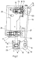
- Fig. 2 shows a housing 25 in which the actuators 1, 2; 4, 5 housed are.
- the shaft 13 is accommodated on the inside of the housing 25 the rocker 12 is seated.
- the one-armed lever 15 is inside the housing 25 arranged on the shaft 13 and via the connector 16 and the ball joint 17 with the connecting rod 18 articulated connected.
- the shaft 13 is in the housing 25 by at least one Seal 26 sealed.
- the shaft 7 is in the housing 25 in the lower end region in FIG. 2 rotatably mounted.
- the one-armed one sits on it within the housing 25 Lever 9, which protrudes downward from the housing 25.
- Within of the housing 25 sits on the shaft 7, the rocker 6.
- the shaft 7 is in Housing 25 sealed by two seals 27, 28.
- the bearing piece 10, as shown in FIG. 1, has a rectangular cross section and is cup-shaped.
- the lever 9 lies with the running disks 29, 30, which are flat on the two opposite outer sides of the lever 9, within the bearing piece 10.
- Die Discs 29, 30 are preferably rotatable about their axes and protrude downward beyond the lever 9.
- the diameter of the running disks 29, 30 is, as FIG. 1 shows, larger than the width of the lever 9.
- the Running disks 29, 30 are freely rotatable, the bearing piece 10 and thus the control shaft 3 with good efficiency in the direction of displacement 11 to shift into gear.
- the flange 20 projecting perpendicularly from the bearing piece 10 has a Elongated hole 32 through which the connector 19 protrudes.
- the slot 32 extends perpendicular to the direction of displacement 11 of the bearing piece 10 or the control shaft 3. It is easy through the slot 32 possible to compensate for 18 tolerances when installing the connecting rod. In the assembled position, the connector 19 is fixed with connected to the flange 20.
- the inner width B of the bearing piece 10 is greater than the length of the Bolt 31 or the distance of the discs 29, 30 from each other. This ensures that the lever 9 with its discs 29, 30 sufficient lateral distance from the inner wall of the Bearing piece 10 has. Therefore, the bearing piece 10 can be without interference through the lever 9 from the connecting rod 18 to Choice of the alley of the gearbox can be pivoted.
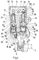
- the two actuators 1, 2 lie within the housing 25 with little Distance parallel next to each other (Fig. 3) and each have two pistons 33, 34 and 35, 36.
- the pistons 33, 35 are sleeve-shaped formed as a hollow piston, which in a cylinder space 37, 38 are guided.
- the two pistons 33, 35 are sealed on the bore wall 39, 40. Near the top are the two pistons 33, 35 reduced in outer diameter, so that an annular space 41, 42 is formed there, which is less extends as half the length of the piston 33, 35.
- the inner pistons lie on the inner wall of the pistons 33, 35 34, 36 without using sealing elements.
- the inner pistons project downwards over the hollow pistons 33, 35 and lie against the free ones Ends 43, 44 of the rocker 6.
- the pistons 34, 36 are close to theirs lower end with a radially outwardly projecting ring flange 45, 46 provided which serves as a stop for the pistons 34, 36. With you are the pistons 34, 36 in the neutral position shown in Fig. 3 an inner annular shoulder surface 47, 48 of the hollow pistons 33, 35.
- the inner pistons 34, 36 are in the neutral position on the free Ends 43, 44 of the rocker 6.
- the hollow pistons 33, 35 are in turn with their lower end faces on stops 49, 50 of a cover 56 at.
- the pistons are 33 to 36 apart from the bottom 51, 52 of the cylinder spaces 37, 38.
- the inner pistons 34, 36 have on their end facing the floors 51, 52 one Projection 53, 54, the diameter of which is smaller than the diameter of the inner piston 34, 36.
- the rocker 6 is located in a rocker space 55, which is detachable Lid 56 is closed.
- the rocker room 55 can during of operation with hydraulic medium. This has the advantage that the pistons 33 to 36 do not have to be reliably sealed and only two inexpensive sealing elements are required.
- Of the Rocker space 55 communicates with the pistons.
- the inner pistons 34, 36 protrude in the neutral position shown in Fig. 1, in the they with their ring flanges 45, 46 on the ring shoulder surfaces 47, 48 the hollow pistons 33, 35 rest against the rocker chamber 55.
- In this lower end of the inner pistons 34, 36 is a closure piece 57, 58 used, that of at least one bore 59, 60 is enforced.
- the hollow bore of the inner Pistons 34, 36 serve to save weight.
- the two actuators 4, 5 are also in the housing 25 housed next to each other at a short distance.
- You have each an outer hollow piston 61, 62, in each of which an inner Piston 63, 64 is slidably guided.
- the hollow pistons 61, 62 are located sealed to an inner wall 65, 66 of bores 67, 68.
- In the area above the pistons 61 to 64 is in a rocker room 69 housed the rocker 12.
- the hollow pistons 61, 62 point outwards at their lower end directed ring flange 70, 71 on, while the inner piston 63, 64 at their upper end facing the rocker 12 with a circumferential ring flange 72, 73 are provided.
- the inner pistons 63, 64 like the inner pistons 34, 36 of the actuators 1, 2, are hollow educated.
- the cavities are closed by locking pieces 74, 75, which are penetrated by at least one bore 76, 77.
- the inner pistons 63, 64 sit on with their lower end faces bolt-shaped pistons 78 and 79.
- the piston 78 is shorter than the piston 79.
- the shorter piston 78 protrudes through a piston bore 80 Cup-shaped bearing piece 81, the bottom 82 of which faces the pistons 61, 63 and is penetrated by the piston bore 80.
- the end face of the bearing piece 81 lies on the floor 83 Cup-shaped bearing piece 84, with its end face on the lid 56 is present. Both bearing pieces 81, 84 are axially immovable a receiving space 85 of the housing 25. As FIG. 4 shows the bearing pieces 81, 84 sealed on the wall of the receiving space 85 at.
- the upper bearing piece 81 lies with a shoulder surface 86 on an annular shoulder 87 of the inner wall of the receiving space 85 at.
- Openings 88 which are evenly distributed, open into the bearing piece 81 are provided over the circumference of the wall of the bearing piece and by the hydraulic medium to act on the bolt-shaped Piston 78 can be introduced. He points to his im End of bearing piece 81 a stop 89 with which the Piston in the position shown in Fig. 4 under pressure due to the pressure medium in the bearing piece 81 at the bottom 82 of the bearing piece 81 abuts.
- the pin-shaped piston 79 also protrudes through a piston bore 90 in the bottom 91 of a bearing piece 92, which is basically the same is formed like the bearing piece 81, but is longer than this.
- a bearing piece 92 which is basically the same is formed like the bearing piece 81, but is longer than this.
- the lower bearing piece 93 on which the bearing piece 92 its face rests, shorter than the bearing piece 84.
- Both bearing pieces 92, 93 are axially immovable in a receiving space 94 of the housing.
- the bearing pieces 92, 93 are sealed on the inner wall of the receiving space 94.
- the top Bearing piece 92 lies with a shoulder surface 95 on a circumferential one Ring shoulder 96 in the inner wall of the receiving space 94.
- Openings 97 which are preferably evenly distributed over the circumference of the bearing piece 92 are provided and via the hydraulic medium can be introduced.
- the piston 79 is acted upon with it, the end lying in the bearing piece 92 with a stop 98 is provided with which it is in the position shown in FIG. 4 abuts the bottom 91 of the bearing piece 92.
- the rocker space 69 can be like the lower rocker space 55 (FIG. 3) Fill with hydraulic medium during operation.
- the pistons 63 to 66 are connected to the rocker room 69 and must therefore cannot be reliably sealed. Inside the seesaw room 69 are the inner pistons 63, 64 at the free ends 99, 100 of the Rocker 12 on.
- FIG. 5 shows the pistons 33 to 36 of the actuators 1, 2 in one position which the shift shaft 3 of the transmission is in the neutral position.
- the inner pistons 34, 36 abut with their flanges 45, 46 the annular shoulder surfaces 47, 48 of the hollow pistons 33, 35, which in turn with their end faces facing the rocker 6 on the cover-side Stops 49, 50 are present.
- the cylinder spaces 37, 38 are connected to directional valves 101, 102. As shown in FIG. 5, they are switched so that the hydraulic medium via lines 103, 104 flows under pressure into the cylinder spaces 37, 38 and thereby the two Pistons 33, 34 and 35, 36 pressurized so that they assume the neutral position shown in Fig. 5.
- the rocker 6 is the same at both ends 43, 44 heavily loaded so that the rocker 6 assumes its central position.
- the Free ends 43, 44 of the rocker 6 are designed so that they in this
- the bores 59, 60 of the closure pieces 57, 58 are in the middle position do not close the inner pistons 34, 36.
- the hydraulic medium is pumped from a tank 105 by a pump 106.
- the directional control valve 101 is switched (Fig. 6) that the pressure chamber 37 to the tank 105 is relieved.
- the Directional control valve 102 remains in its switch position in which it is in the pressure chamber 38 hydraulic medium under pressure remains.
- the pressure chamber 37 of the actuator 1 is relieved towards the tank 105, the inner piston 36 of the actuator 2 becomes under the hydraulic medium pressure 6 moved downwards in the position according to FIG. Since the Hollow piston 35 abuts the cover-side stop 50, the hollow piston becomes 35 not moved by pressurization.
- the directional valves 101, 102 To move from the positions shown in FIG. 6 or 7 to the middle position 5, the directional valves 101, 102 must be in the 5 are switched position. This over the lines 103, 104 supplied hydraulic medium acts on the upper Stop position at a distance from the floor 51, 52 of the pressure chambers 37, 38 end faces of the respective pistons 33, 34 or 35, 36.
- the annular spaces 41, 42 are formed by shoulder surfaces 107, 108 bounded on the outer wall of the hollow piston 33, 35. This ring-shaped shoulder surfaces are also optionally with the Hydraulic medium applied.
- the hollow piston 33 or 35 takes over the ring shoulder surface 47 or 48 the inner piston 34 or 36 with. With the piston 35, 36 in the lower position (Fig. 6) or 33, 34 (Fig.
- Fig. 8 shows the actuators 4, 5 in a position in which the alley I has been selected for gears 1 and 2.
- the actuators 4, 5 two directional valves 109 and 110 are assigned.
- Directional control valve 110 is switched so that the hydraulic medium from the tank 105 a line 111 and a bore 119 enter a pressure chamber 112, that between the bearing piece 92 and the two pistons 62, 64 of the actuator 5 lies. Since the hydraulic medium in the pressure chamber 112 is under pressure, both pistons 62, 64 towards the Rocker 12 loaded.
- the hollow piston 62 lies with its ring flange 71 on an annular shoulder 113 on the inner wall of the bore 68 is provided.
- the inner piston 64 is under pressure of the hydraulic medium in the direction of the rocker 12.
- hydraulic medium is supplied via a line 114 via the Opening 97 promoted in the bearing piece 92, the interior of which one Pressure chamber 115 forms.
- the piston 79 is loaded upward so that it with his Ring stop 98 abuts the bottom 91 of the bearing piece 92.
- the piston 64 loads the rocker 12 in the illustration according to FIG. 8 counter clockwise. This causes the piston 63 of the actuator 4 charged down.
- the piston 63 lies with its ring flange 72 on the end face of the hollow piston facing the rocker 12 61 on and thereby also puts him down.
- the ring flange 70 of the hollow piston 61 is at a distance from an annular shoulder 116, which is provided in the inner wall of the bore 67.
- a pressure chamber 117 into which a line 118 opens, via the directional valve 109 to the tank 105 is relieved.
- the bearing piece 81 contains a pressure chamber 120, in which one Line 121 can be introduced via the opening 88 hydraulic medium can. 8 in the pressure chamber 120 hydraulic medium under pressure, so that the stop 89 of the piston 80 is pressurized.
- the piston 80 is thereby moved upwards until it hits its stop 89 within the pressure chamber 120 at the bottom 82 of the bearing piece 81 is present.
- the piston 80 projects into the pressure chamber 117 and supports the inner piston 63 against the force of the rocker 12. Of the Pressure in the pressure chamber 120 thus generates a force that is greater than on the piston 63 from the rocker 12 in the opposite direction exerted force.
- the directional control valve 109 is only based on the position according to Fig. 8, switched. Now the hydraulic medium is in the pressure chamber 117 pressurized via line 118. This will both pistons 61, 63 acted upon by pressure medium and thereby moved upwards until the hollow piston 61 with its ring flange 70 on the housing-side ring shoulder 116 to the system is coming. Here, the inner piston 63 lifts off from the piston 80, which is still under pressure in the pressure chamber 120 and thereby with its stop 89 in contact with the bottom 82 of the bearing piece 81 is held.
- the sum of the areas of the pistons applied in the pressure chamber 117 61, 63 is larger than the acted effective area of the piston 64 in the pressure chamber 112. Since the hollow piston 62 with its ring flange 71 is supported on the housing-side ring shoulder the area of this hollow piston 62 acted upon in the pressure chamber 112 not effective. This causes the rocker 12 to move through the piston 63 9 pivoted clockwise, wherein the shaft 13 is rotated clockwise about its axis. On the Lever 15 and the connecting rod 18 is the selector shaft 3 by the bearing piece 10 rotated accordingly. The rocker end 100 pushes the piston 64 down. The hollow piston 62 remains in its Position compared to the position shown in FIG. 8.
- the two pistons 79, 80 have a diameter that is smaller than the diameter of the face of the inner piston 63, 64. Due to the diameter ratios described and the pressure ratios in the pressure chambers 112, 115 it is achieved that the inner Piston 64 through the pin-shaped piston 79 in FIG. 9 shown middle position is held.
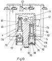
- the shaft 13 can continue clockwise 10 to be adjusted to the alley III to be selected for the fifth gear of the manual transmission.
- the pressure room In this case 112 is relieved towards tank 105.
- the counterforce acting on the rocker 12 only from the im Pressure chamber 115 acts on the surface of the piston 79.
- the pressure chamber 117 of the actuator 4 continues to be pressurized , the inner piston 63 can now move further upwards relative to be displaced to the hollow piston 61.
- the hollow piston 61 remains with its ring flange 70 in contact with the housing Ring shoulder 116.
- FIG. 11 shows the position of the pistons of the two actuators 4 and 5 when the alley IV is approached to engage reverse gear R. has been.
- the Relieved pressure chamber 117 of the actuator 4 to the tank 105.
- the pressure chamber 112 of the actuator is via the directional valve 110 5 continues to be pressurized so that the inner piston 64 is driven upwards.
- the hollow piston 62 lies with his Ring flange 71 on the housing-side ring shoulder 113 and can will not be moved any further.
- the rocker 12 rotated counterclockwise. It shifts through it the inner piston 63 of the actuator 4 due to the pressure relief downward.
- the inner piston 62 takes over its ring flange 72 with the hollow piston 61.
- the pin-shaped piston 80 whose area in the pressure chamber 120 is smaller than that in the Pressure area 112 acted upon surface of the piston 64, thereby pushed into the bearing piece 81.
- the rocker 12 is so far through the piston 64 pivoted until the inner piston 63 at the bottom 82 of the bearing piece 81 or the piston 80 on the bearing piece 88 for contact is coming.
- the actuators 1, 2, 4, 5 are located directly axially parallel within of the housing 25 side by side. As a result, this actuator has one extremely compact shape so that it can be accommodated in vehicles can be in which only very small installation spaces for the actuator be available.
- the actuator works extremely reliable.
- To the described adjustment movements of the actuators To trigger 1, 2, 4, 5, switch buttons can be provided in the motor vehicle be that only need to be pressed to get the required Adjustment movements of the individual pistons of the actuators trigger.
- the described turning and Shifting movements of the selector shaft 3 run within a very short time Times from, so that the desired courses can be engaged quickly. This makes sporty driving particularly easy possible.
- the described and shown axis-parallel arrangement of the actuators 1, 2, 4, 5 is an optimal one for manufacturing and assembly Solution. If the installation conditions require it, at least one of the actuators is also arranged at an angle to its counteractuator be. In this case, the two arms of the associated lie Rocker no longer in alignment, but offset and at an angle to each other.
- the directional control valves 101, 102 are preferably proportional directional control valves with pressure feedback (pressure reducing valves) to the pressure during modulate the engagement of the gear and the synchronization process to be able to.
- the shafts 7, 13 each have a rotary measuring system 123, 124 assigned (Fig. 1 to 3).
- the measuring systems 123 are preferably 124 potentiometers; but they can also be non-contact be provided.
Landscapes
- Engineering & Computer Science (AREA)
- General Engineering & Computer Science (AREA)
- Mechanical Engineering (AREA)
- Gear-Shifting Mechanisms (AREA)
- Valve Device For Special Equipments (AREA)
Abstract
Description
- Fig. 1
- in perspektivischer und schematischer Darstellung einen erfindungsgemäßen Stellantrieb,
- Fig. 2
- in vergrößerter Darstellung und teilweise im Schnitt die Verbindung zwischen einer Welle des Stellantriebes und einer Schaltwelle eines Getriebes,
- Fig. 3
- in vergrößerter Darstellung und teilweise im Schnitt zwei Aktuatoren des erfindungsgemäßen Stellantriebes zum Verschieben der Schaltwelle des Getriebes,
- Fig. 4
- in vergrößerter Darstellung und teilweise im Schnitt zwei Aktuatoren des erfindungsgemäßen Stellantriebes zum Drehen der Schaltwelle des Getriebes um ihre Achse,
- Fig. 5
- die Aktuatoren des erfindungsgemäßen Stellantriebes zum Verschieben der Schaltwelle in einer Neutralposition,
- Fig. 6 und Fig. 7
- die Aktuatoren des erfindungsgemäßen Stellantriebes zum Verschieben der Schaltwelle in verschiedenen Schaltstellungen, in denen unterschiedliche Gänge eingelegt werden,
- Fig. 8 bis Fig. 11
- jeweils im Schnitt die Aktuatoren des erfindungsgemäßen Stellantriebes zum Drehen der Schaltwelle in unterschiedlichen Schaltstellungen zum Anwählen unterschiedlicher Gassen.
Claims (17)
- Stellantrieb für Schaltgetriebe von Kraftfahrzeugen, mit Aktuatoren, mit denen eine Dreh- und eine Verschiebebewegung einer Schaltwelle des Schaltgetriebes ausgeführt wird, um Gassen des Schaltgetriebes anzufahren und Gänge einzulegen, dadurch gekennzeichnet, daß die Aktuatoren (1, 2; 4, 5) parallel nebeneinander in einem Gehäuse (25) untergebracht sind.
- Stellantrieb nach Anspruch 1,
dadurch gekennzeichnet, daß zur Gassenwahl des Schaltgetriebes zwei Aktuatoren (4, 5) vorgesehen sind, die auf gleicher Höhe nebeneinander liegen. - Schaltgetriebe, insbesondere nach Anspruch 1 oder 2,
dadurch gekennzeichnet, daß die beiden Aktuatoren (4, 5) zur Gassenwahl mit einer Wippe (12) zusammenwirken, die auf einer Welle (13) drehfest sitzt, die vorzugsweise senkrecht zur Achsrichtung der Aktuatoren (4, 5) liegt. - Stellantrieb nach Anspruch 3,
dadurch gekennzeichnet, daß auf der Welle (13) drehfest ein Hebel (15) sitzt, der über eine Verbindungsstange (18) gelenkig mit einem an der Schaltwelle (3) vorgesehenen Anlenkstück (10) verbunden ist. - Stellantrieb nach einem der Ansprüche 1 bis 4,
dadurch gekennzeichnet, daß zum Einlegen des Ganges des Schaltgetriebes zwei Aktuatoren (1, 2) vorgesehen sind, die auf gleicher Höhe nebeneinander liegen. - Stellantrieb, insbesondere nach einem der Ansprüche 1 bis 5,
dadurch gekennzeichnet, daß die beiden Aktuatoren (1, 2) zum Gangeinlegen mit einer weiteren Wippe (6) zusammenwirken, die auf einer weiteren Welle (7) drehfest sitzt, auf der vorzugsweise drehfest ein Hebel (9) sitzt, der mit dem Anlenkstück (10) der Schaltwelle (3) zusammenwirkt. - Stellantrieb nach Anspruch 6,
dadurch gekennzeichnet, daß die weitere Welle (7) senkrecht zur Achse der Aktuatoren (1, 2) liegt. - Stellantrieb nach einem der Ansprüche 3 bis 7,
dadurch gekennzeichnet, daß die beiden Wellen (7, 13) der Wippen (6, 12) parallel zueinander liegen. - Stellantrieb nach einem der Ansprüche 3 bis 8,
dadurch gekennzeichnet, daß die beiden Wellen (7, 13) der Wippen (6, 12) beiderseits der Aktuatoren (1, 2; 4, 5) angeordnet sind. - Stellantrieb nach einem der Ansprüche 4 bis 9,
dadurch gekennzeichnet, daß das Anlenkstück (10) fest mit der Schaltwelle (3) verbunden und vorzugsweise als Hohlkörper ausgebildet ist, in den der Hebel (9) der weiteren Welle (7) eingreift. - Stellantrieb nach einem der Ansprüche 5 bis 10,
dadurch gekennzeichnet, daß die Hebel (9, 15) der beiden Wellen (7, 13) der Wippen (6, 12) winklig zueinander liegen. - Stellantrieb nach einem der Ansprüche 1 bis 11,
dadurch gekennzeichnet, daß die Aktuatoren (1, 2; 4, 5) jeweils mindestens zwei gegeneinander bewegliche Kolben (33 bis 36; 61 bis 64; 79, 80) aufweisen. - Stellantrieb nach Anspruch 12,
dadurch gekennzeichnet, daß die Kolben (33 bis 36; 61 bis 64) jedes Aktuators (1, 2; 4, 5) ineinander liegen. - Stellantrieb nach einem der Ansprüche 1 bis 13,
dadurch gekennzeichnet, daß jedem Aktuator (1, 2; 4, 5) ein Wegeventil (101, 102; 109, 110) zugeordnet ist. - Stellantrieb nach einem der Ansprüche 3 bis 14,
dadurch gekennzeichnet, daß zumindest die eine Wippe, vorzugsweise beide Wippen (6, 12), in einem Wippenraum (55, 69) des Gehäuses (25) liegen, der mit Hydraulikmedium füllbar ist, und daß vorteilhaft die Welle (7, 13) der jeweiligen Wippe (6, 12) mit wenigstens einer Dichtung (26 bis 28) abgedichtet ist. - Stellantrieb nach Anspruch 15,
dadurch gekennzeichnet, daß die Kolben (33 bis 36, 61 bis 64) der Aktuatoren (1, 2; 4, 5) in den jeweiligen Wippenraum (55, 69) ragen. - Stellantrieb nach einem der Ansprüche 1 bis 16,
dadurch gekennzeichnet, daß die Aktuatoren (4, 5) zur Gassenwahl jeweils einen Hilfskolben (79, 80) aufweisen. 18. Stellantrieb nach einem der Ansprüche 1 bis 17, dadurch gekennzeichnet, daß den Wellen (7, 13) jeweils ein rotatorisches Meßsystem (123, 124) zugeordnet ist.
Applications Claiming Priority (2)
| Application Number | Priority Date | Filing Date | Title |
|---|---|---|---|
| DE19740090A DE19740090A1 (de) | 1997-09-12 | 1997-09-12 | Stellantrieb für Schaltgetriebe von Kraftfahrzeugen |
| DE19740090 | 1997-09-12 |
Publications (3)
| Publication Number | Publication Date |
|---|---|
| EP0902217A2 true EP0902217A2 (de) | 1999-03-17 |
| EP0902217A3 EP0902217A3 (de) | 1999-11-03 |
| EP0902217B1 EP0902217B1 (de) | 2003-06-25 |
Family
ID=7842118
Family Applications (1)
| Application Number | Title | Priority Date | Filing Date |
|---|---|---|---|
| EP98115597A Expired - Lifetime EP0902217B1 (de) | 1997-09-12 | 1998-08-19 | Stellantrieb für Schaltgetriebe von Kraftfahreugen |
Country Status (5)
| Country | Link |
|---|---|
| US (1) | US6223617B1 (de) |
| EP (1) | EP0902217B1 (de) |
| JP (1) | JPH11153220A (de) |
| DE (2) | DE19740090A1 (de) |
| ES (1) | ES2196443T3 (de) |
Cited By (1)
| Publication number | Priority date | Publication date | Assignee | Title |
|---|---|---|---|---|
| EP1275886A3 (de) * | 2001-07-02 | 2008-12-10 | Isuzu Motors Limited | Schaltaktuator für ein Getriebe |
Families Citing this family (5)
| Publication number | Priority date | Publication date | Assignee | Title |
|---|---|---|---|---|
| DE19931973A1 (de) * | 1999-07-09 | 2001-01-11 | Wabco Gmbh & Co Ohg | Einrichtung zum Steuern einer Stelleinrichtung für ein Getriebe |
| WO2003069193A1 (de) * | 2002-02-18 | 2003-08-21 | Tesma Motoren- Und Getriebetechnik Gmbh | Schaltvorrichtung mit vier schaltstellungen |
| DE102009026544A1 (de) * | 2009-05-28 | 2010-12-02 | Zf Friedrichshafen Ag | Wählsteller für ein automatisiertes Getriebe eines Kraftfahrzeugs |
| DE102016107661A1 (de) * | 2016-04-25 | 2017-10-26 | Kendrion (Villingen) Gmbh | Elektromagnetische Stellvorrichtung mit D-förmiger Spule für 2-Pin-Aktor |
| US11235460B2 (en) | 2018-09-24 | 2022-02-01 | Salesforce.Com, Inc. | Techniques and architectures for managing heterogeneous robots to manage deliveries |
Family Cites Families (7)
| Publication number | Priority date | Publication date | Assignee | Title |
|---|---|---|---|---|
| DE2517456A1 (de) * | 1975-04-19 | 1976-10-28 | Bosch Gmbh Robert | Gangschaltvorrichtung fuer wechselgetriebe |
| JPS63303247A (ja) * | 1987-05-30 | 1988-12-09 | Diesel Kiki Co Ltd | 自動変速装置 |
| DE69108801T2 (de) * | 1990-01-31 | 1995-08-24 | Komatsu Mfg Co Ltd | Bedienungshebel. |
| FR2670265B3 (fr) * | 1990-12-07 | 1992-12-31 | Valeo | Dispositif de commande motorise de changement de rapports de transmission pour boite de vitesses, en particulier pour vehicules automobiles. |
| DE4311855A1 (de) * | 1993-04-10 | 1994-10-13 | Hydraulik Ring Gmbh | Stellantriebssystem für Schaltgetriebe von Kraftfahrzeugen |
| DE19507705A1 (de) * | 1995-03-04 | 1996-09-05 | Hydraulik Ring Gmbh | Stellantriebssystem für Schaltgetriebe von Kraftfahrzeugen |
| DE19606756A1 (de) * | 1996-02-23 | 1997-08-28 | Hydraulik Ring Gmbh | Stelleinrichtung zur Automatisierung von Handschaltgetrieben von Kraftfahrzeugen |
-
1997
- 1997-09-12 DE DE19740090A patent/DE19740090A1/de not_active Withdrawn
-
1998
- 1998-08-19 ES ES98115597T patent/ES2196443T3/es not_active Expired - Lifetime
- 1998-08-19 EP EP98115597A patent/EP0902217B1/de not_active Expired - Lifetime
- 1998-08-19 DE DE59808797T patent/DE59808797D1/de not_active Expired - Fee Related
- 1998-09-11 US US09/151,884 patent/US6223617B1/en not_active Expired - Lifetime
- 1998-09-11 JP JP10258984A patent/JPH11153220A/ja active Pending
Non-Patent Citations (1)
| Title |
|---|
| None |
Cited By (1)
| Publication number | Priority date | Publication date | Assignee | Title |
|---|---|---|---|---|
| EP1275886A3 (de) * | 2001-07-02 | 2008-12-10 | Isuzu Motors Limited | Schaltaktuator für ein Getriebe |
Also Published As
| Publication number | Publication date |
|---|---|
| DE59808797D1 (de) | 2003-07-31 |
| US6223617B1 (en) | 2001-05-01 |
| JPH11153220A (ja) | 1999-06-08 |
| ES2196443T3 (es) | 2003-12-16 |
| DE19740090A1 (de) | 1999-03-18 |
| EP0902217B1 (de) | 2003-06-25 |
| EP0902217A3 (de) | 1999-11-03 |
Similar Documents
| Publication | Publication Date | Title |
|---|---|---|
| DE10113161A1 (de) | Stelleinrichtung für automatisierte Handschaltgetriebe von Fahrzeugen, vorzugsweise von Kraftfahrzeugen | |
| DE1755840C2 (de) | Stufenlos verstellbares Reibrollengetriebe für Fahrzeuge | |
| EP0731297B1 (de) | Stellantriebssystem für Schaltgetriebe von Kraftfahrzeugen | |
| DE19909347A1 (de) | Getriebe | |
| DE2828347A1 (de) | Reibgetriebe | |
| DE4311855A1 (de) | Stellantriebssystem für Schaltgetriebe von Kraftfahrzeugen | |
| EP0731298B1 (de) | Stellantrieb für Schaltgetriebe von Kraftfahrzeugen | |
| EP0791770B1 (de) | Stelleinrichtung zur Automatisierung von Handschaltgetrieben von Kraftfahrzeugen | |
| DE4444952A1 (de) | Kontinuierlich-variables Reibrollengetriebe | |
| DE69029621T2 (de) | Stufenloses Toroidrollengetriebe mit Übersetzungssteuerung | |
| DE69010705T2 (de) | Steuerungssystem für ein Triebrollengetriebe. | |
| DE4406598A1 (de) | Kraftfahrzeug mit einem selbsttätig schaltenden Wechselgetriebe und einer mechanischen Sperre für den Rückwärtsgang | |
| EP0902217B1 (de) | Stellantrieb für Schaltgetriebe von Kraftfahreugen | |
| EP0620387A2 (de) | Stellantrieb für Schaltgetriebe von Kraftfahrzeugen | |
| DE4446426A1 (de) | Stufenloses Toroidgetriebe | |
| EP1130293A2 (de) | Steuereinrichtung für automatisierte Schaltgetriebe von Fahrzeugen, vorzugsweise von Kraftfahrzeugen | |
| DE2655263C2 (de) | Schalteinrichtung für ein aus einem Haupt- und einem Zweibereichs- Gruppengetriebe bestehenden Zahnräderwechselgetriebe | |
| DE2947651C2 (de) | Einrichtung zur Stellungsrückführung der Steuerhülse eines Steuerventils einer hydraulischen Maschine | |
| DE2813099A1 (de) | Doppel-h-schaltung fuer ein vielganggetriebe | |
| DE102022114776B3 (de) | Kopplungseinheit zur reversiblen Kopplung einer Antriebsseite mit einer Abtriebsseite eines Antriebsstrangs | |
| DE69127941T2 (de) | Drehkolbenantrieb mit innerem Ventil | |
| DE10240259A1 (de) | Gangschaltstellglieder | |
| DE1919576A1 (de) | Hydraulische Fernsteuerung | |
| DE19927268A1 (de) | Stufenlos verstellbares Toroidgetriebe | |
| DE4237463C2 (de) | Ausgleichsgetriebe |
Legal Events
| Date | Code | Title | Description |
|---|---|---|---|
| PUAI | Public reference made under article 153(3) epc to a published international application that has entered the european phase |
Free format text: ORIGINAL CODE: 0009012 |
|
| AK | Designated contracting states |
Kind code of ref document: A2 Designated state(s): DE ES FR GB IT SE |
|
| AX | Request for extension of the european patent |
Free format text: AL;LT;LV;MK;RO;SI |
|
| PUAL | Search report despatched |
Free format text: ORIGINAL CODE: 0009013 |
|
| AK | Designated contracting states |
Kind code of ref document: A3 Designated state(s): AT BE CH CY DE DK ES FI FR GB GR IE IT LI LU MC NL PT SE |
|
| AX | Request for extension of the european patent |
Free format text: AL;LT;LV;MK;RO;SI |
|
| 17P | Request for examination filed |
Effective date: 20000211 |
|
| AKX | Designation fees paid |
Free format text: DE ES FR GB IT SE |
|
| 17Q | First examination report despatched |
Effective date: 20010828 |
|
| GRAG | Despatch of communication of intention to grant |
Free format text: ORIGINAL CODE: EPIDOS AGRA |
|
| GRAG | Despatch of communication of intention to grant |
Free format text: ORIGINAL CODE: EPIDOS AGRA |
|
| GRAH | Despatch of communication of intention to grant a patent |
Free format text: ORIGINAL CODE: EPIDOS IGRA |
|
| GRAH | Despatch of communication of intention to grant a patent |
Free format text: ORIGINAL CODE: EPIDOS IGRA |
|
| GRAA | (expected) grant |
Free format text: ORIGINAL CODE: 0009210 |
|
| AK | Designated contracting states |
Designated state(s): DE ES FR GB IT SE |
|
| REG | Reference to a national code |
Ref country code: GB Ref legal event code: FG4D Free format text: NOT ENGLISH |
|
| REF | Corresponds to: |
Ref document number: 59808797 Country of ref document: DE Date of ref document: 20030731 Kind code of ref document: P |
|
| GBT | Gb: translation of ep patent filed (gb section 77(6)(a)/1977) |
Effective date: 20030806 |
|
| REG | Reference to a national code |
Ref country code: SE Ref legal event code: TRGR |
|
| REG | Reference to a national code |
Ref country code: ES Ref legal event code: FG2A Ref document number: 2196443 Country of ref document: ES Kind code of ref document: T3 |
|
| ET | Fr: translation filed | ||
| PLBE | No opposition filed within time limit |
Free format text: ORIGINAL CODE: 0009261 |
|
| STAA | Information on the status of an ep patent application or granted ep patent |
Free format text: STATUS: NO OPPOSITION FILED WITHIN TIME LIMIT |
|
| 26N | No opposition filed |
Effective date: 20040326 |
|
| PGFP | Annual fee paid to national office [announced via postgrant information from national office to epo] |
Ref country code: SE Payment date: 20050804 Year of fee payment: 8 |
|
| PGFP | Annual fee paid to national office [announced via postgrant information from national office to epo] |
Ref country code: ES Payment date: 20050812 Year of fee payment: 8 |
|
| PGFP | Annual fee paid to national office [announced via postgrant information from national office to epo] |
Ref country code: FR Payment date: 20060717 Year of fee payment: 9 |
|
| PGFP | Annual fee paid to national office [announced via postgrant information from national office to epo] |
Ref country code: GB Payment date: 20060816 Year of fee payment: 9 |
|
| PG25 | Lapsed in a contracting state [announced via postgrant information from national office to epo] |
Ref country code: SE Free format text: LAPSE BECAUSE OF NON-PAYMENT OF DUE FEES Effective date: 20060820 |
|
| PGFP | Annual fee paid to national office [announced via postgrant information from national office to epo] |
Ref country code: IT Payment date: 20060831 Year of fee payment: 9 |
|
| EUG | Se: european patent has lapsed | ||
| REG | Reference to a national code |
Ref country code: ES Ref legal event code: FD2A Effective date: 20060821 |
|
| PG25 | Lapsed in a contracting state [announced via postgrant information from national office to epo] |
Ref country code: ES Free format text: LAPSE BECAUSE OF NON-PAYMENT OF DUE FEES Effective date: 20060821 |
|
| GBPC | Gb: european patent ceased through non-payment of renewal fee |
Effective date: 20070819 |
|
| REG | Reference to a national code |
Ref country code: FR Ref legal event code: ST Effective date: 20080430 |
|
| PG25 | Lapsed in a contracting state [announced via postgrant information from national office to epo] |
Ref country code: FR Free format text: LAPSE BECAUSE OF NON-PAYMENT OF DUE FEES Effective date: 20070831 |
|
| PGFP | Annual fee paid to national office [announced via postgrant information from national office to epo] |
Ref country code: DE Payment date: 20080822 Year of fee payment: 11 |
|
| PG25 | Lapsed in a contracting state [announced via postgrant information from national office to epo] |
Ref country code: GB Free format text: LAPSE BECAUSE OF NON-PAYMENT OF DUE FEES Effective date: 20070819 |
|
| PG25 | Lapsed in a contracting state [announced via postgrant information from national office to epo] |
Ref country code: IT Free format text: LAPSE BECAUSE OF NON-PAYMENT OF DUE FEES Effective date: 20070819 |
|
| PG25 | Lapsed in a contracting state [announced via postgrant information from national office to epo] |
Ref country code: DE Free format text: LAPSE BECAUSE OF NON-PAYMENT OF DUE FEES Effective date: 20100302 |