EP0902751B1 - Procede d'evacuation de l'air dans un systeme de direction hydraulique assistee - Google Patents
Procede d'evacuation de l'air dans un systeme de direction hydraulique assistee Download PDFInfo
- Publication number
- EP0902751B1 EP0902751B1 EP96922808A EP96922808A EP0902751B1 EP 0902751 B1 EP0902751 B1 EP 0902751B1 EP 96922808 A EP96922808 A EP 96922808A EP 96922808 A EP96922808 A EP 96922808A EP 0902751 B1 EP0902751 B1 EP 0902751B1
- Authority
- EP
- European Patent Office
- Prior art keywords
- hydraulic
- resonator
- valve
- oil
- air
- Prior art date
- Legal status (The legal status is an assumption and is not a legal conclusion. Google has not performed a legal analysis and makes no representation as to the accuracy of the status listed.)
- Expired - Lifetime
Links
Images
Classifications
-
- B—PERFORMING OPERATIONS; TRANSPORTING
- B62—LAND VEHICLES FOR TRAVELLING OTHERWISE THAN ON RAILS
- B62D—MOTOR VEHICLES; TRAILERS
- B62D5/00—Power-assisted or power-driven steering
- B62D5/06—Power-assisted or power-driven steering fluid, i.e. using a pressurised fluid for most or all the force required for steering a vehicle
- B62D5/062—Details, component parts
-
- F—MECHANICAL ENGINEERING; LIGHTING; HEATING; WEAPONS; BLASTING
- F15—FLUID-PRESSURE ACTUATORS; HYDRAULICS OR PNEUMATICS IN GENERAL
- F15B—SYSTEMS ACTING BY MEANS OF FLUIDS IN GENERAL; FLUID-PRESSURE ACTUATORS, e.g. SERVOMOTORS; DETAILS OF FLUID-PRESSURE SYSTEMS, NOT OTHERWISE PROVIDED FOR
- F15B21/00—Common features of fluid actuator systems; Fluid-pressure actuator systems or details thereof, not covered by any other group of this subclass
- F15B21/04—Special measures taken in connection with the properties of the fluid
Definitions
- the present invention relates to a hydraulic power steering system and a Process for venting it with oil release volumes.
- DE 35 38 670 a valve-controlled ventilation Automotive cooler.
- DE 19 01 776 describes a device for automatic venting of hydraulic systems using a spring-loaded Piston / cylinder arrangement known.
- DE 41 20 665 discloses one Hydraulic pump driven by an electric motor, characterized by a compact and installation-friendly design.
- DE 40 40 003 discloses one Power steering for vehicles, with expansion tank only on the edge Ventilation are described, which are so-called air separator elements, too which have direct hydraulic lines.
- DE 24 06 565 relates to a Power steering with a vent in the form of a spring-loaded ball is trained.
- DE 43 26 580 discloses a device for Degassing a hydraulic system, which is an additional component in the form proposes a drum-shaped separator in the area of the storage container.
- servo steering systems of the generic type kind known in which from a servo pump a pressure medium, usually Hydraulic oil, via a power steering valve in the chambers of a hydraulic Steering gear is guided.
- a pressure medium usually Hydraulic oil
- So-called air accumulations occur, which are undesirable and sometimes unpleasant tax results.
- so-called oil expansion volumes are formed in hydraulic systems, for example if resonators are used. The air can open up different ways arise, for example by leakage, by Elimination from the print medium and the like.
- Oil release volumes for example the resonator
- the Oil release volumes have a dome, in which air can collect because the dome is in the installed position upwards points, a lot of air will collect in the dome over time and lead to severe disruptions due to foaming and a consequent Increased wear on the pump.
- the present invention is based on the object of specifying a method for reducing air inclusions.
- the invention is intended to provide a hydraulic power steering system which, with reduced air proportions, does not have the disadvantages that are generated by air pockets.
- the invention proposes a hydraulic power steering system with at least one oil expansion volume in the form of a resonator arranged on a hydraulic pump, which in the upper region in the installed position has a connection to a tank volume, which is produced by a valve which is directly connected to protrudes the tank, and which is used at the same time as a vent and as a suction valve.
- the Invention uses a connecting line.
- the connecting line is realized by a valve or has one.
- the invention can be particularly advantageous in the case of a hydraulic one Use a power steering system in which a resonator is integrated.
- the resonator is a Volume element, which has a plurality of chambers, the Pressure pulsation of the hydraulic oil in the resonator is reduced. It is known that directly in an upper area of the hydraulic pump the resonator is arranged.
- a tank usually a plastic part, surrounds both part of the pump as well as the resonator.
- a valve in the upper region of the resonator or a relaxation volume arranged a valve.
- This valve opens according to an advantageous proposal of the invention depending on the pressure.
- This pressure-dependent opening / closing valve protrudes according to an advantageous one Proposal of the invention directly in the tank. So it gathers within the Resonators with time air, it becomes dependent on the hydraulic pressure regularly in an open system, i.e. the tank is discharged.
- valve according to the invention a previously provided on a hydraulic pump Valve with originally different function replaced.
- the air can collect in a hydraulic system in different ways. First of all, this can be done when filling a pump or when refilling the system done during operation. It is also known that, for example, by Cavitation, chemical decomposition, leakage and the like can arise in a hydraulic system.
- the air is through the regular Oil volume flow not conveyed out of the system. It gathers in top Volume ranges, for example in a resonator cover. This especially when the resonator cover is dome-shaped. The one in the system Any remaining air foams the extracted oil. This worsens it Noise behavior and can tear off the lubricating film in the pump and thus reduce the lifespan.
- the valve is closed and guaranteed at higher pressures thus the normal operation of the pump and resonator.
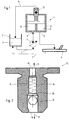
- FIG. 1 shows a hydraulic system 1, in which in a tank 2 Hydraulic oil 3 is added.
- the oil 3 of a pump 5 is fed via a line 4 supplied, the amount of oil via a valve, not shown, a steering gear 6 is supplied.
- the oil finally comes back in via a line 7 the tank 2.
- Embodiment 8 Is shown between the pump 5 and the steering gear 6 in Embodiment arranged a resonator 8.
- Chambers 10, 11 are in the resonator 8 formed so that the oil leaves the resonator through the bore 12.
- the resonator 8 serves to reduce pressure pulsations.
- valve 13 arranged in the dome of the resonator 8, in Depending on the specified parameters, accumulated air via the line 14 are returned to tank 2.
- the operating parameters according to which Valve 13 opens or closes, can be set as desired.
- a suitable one The parameter is the hydraulic pressure.
- the resonator In modern and known pumps, the resonator is directly on the Pump attached. In this case a hole from the pump leads directly into the Resonator. The hydraulic oil then passes through different chambers and arrives via another hole in the further circuit. In the shown The embodiment is the inlet bore in the resonator 8, the bore 9. Das Hydraulic oil passes through several chambers 10, 11 and leaves the resonator via the Hole 12.
- FIG. 13 An exemplary embodiment of a valve 13 is shown in FIG.
- the valve 13 has a through hole in which a spring 16 in a spring chamber 15 is arranged.
- the spring 16 is a in the embodiment shown Coil spring, which pressed a ball 17 against a locking cam 18
- the valve 13 is open for suction. From a given pressure the ball 17 pressed against the force of the spring 16 by the cam 18 and against the sealing seat 20 closed.
- the valve 13 is of a type known per se.
- the Air that can be foamed with oil or can have oil leaves the Resonator via valve 13 and connection 19 in an open system, for example tank 2.
Landscapes
- Engineering & Computer Science (AREA)
- Chemical & Material Sciences (AREA)
- Mechanical Engineering (AREA)
- Combustion & Propulsion (AREA)
- Transportation (AREA)
- Analytical Chemistry (AREA)
- Physics & Mathematics (AREA)
- Fluid Mechanics (AREA)
- General Engineering & Computer Science (AREA)
- Fluid-Pressure Circuits (AREA)
- Power Steering Mechanism (AREA)
Claims (2)
- Système hydraulique de direction assistée caractérisé par au moins un volume de détente de l'huile se présentant sous la forme d'un résonateur disposé sur une pompe hydraulique, résonateur qui présente dans sa zone supérieure en position de montage une liaison avec un volume de réservoir, liaison qui est établie au moyen d'une vanne, qui pénètre directement dans le réservoir, et qui est utilisée en même temps comme vanne de désaération et comme vanne de réaspiration.
- Système de direction assistée selon la revendication 1, caractérisé en ce que la vanne se ferme en fonction de la pression.
Applications Claiming Priority (1)
| Application Number | Priority Date | Filing Date | Title |
|---|---|---|---|
| PCT/EP1996/002571 WO1997047510A1 (fr) | 1996-06-14 | 1996-06-14 | Procede d'evacuation de l'air dans un systeme de direction hydraulique assistee |
Publications (2)
| Publication Number | Publication Date |
|---|---|
| EP0902751A1 EP0902751A1 (fr) | 1999-03-24 |
| EP0902751B1 true EP0902751B1 (fr) | 1999-10-27 |
Family
ID=8166234
Family Applications (1)
| Application Number | Title | Priority Date | Filing Date |
|---|---|---|---|
| EP96922808A Expired - Lifetime EP0902751B1 (fr) | 1996-06-14 | 1996-06-14 | Procede d'evacuation de l'air dans un systeme de direction hydraulique assistee |
Country Status (5)
| Country | Link |
|---|---|
| US (1) | US6164927A (fr) |
| EP (1) | EP0902751B1 (fr) |
| JP (1) | JP3695761B2 (fr) |
| DE (1) | DE59603518D1 (fr) |
| WO (1) | WO1997047510A1 (fr) |
Cited By (2)
| Publication number | Priority date | Publication date | Assignee | Title |
|---|---|---|---|---|
| DE102009020064A1 (de) * | 2009-05-06 | 2010-11-11 | Dürr Systems GmbH | Fluidventil, insbesondere Rückführventil für eine Lackieranlage |
| DE102006051608B4 (de) * | 2006-11-02 | 2017-07-13 | Volkswagen Ag | Hydraulische Lenkung |
Families Citing this family (10)
| Publication number | Priority date | Publication date | Assignee | Title |
|---|---|---|---|---|
| DE59608848D1 (de) * | 1996-09-26 | 2002-04-11 | Trw Fahrwerksyst Gmbh & Co | Verfahren zur Entlüftung eines hydraulischen Servolenksystems |
| FR2789446B1 (fr) † | 1999-02-04 | 2002-03-08 | Hydroperfect Internat Hpi | Pompe hydraulique du type a engrenage et groupe electro-pompe equipe d'une telle pompe |
| US6783334B2 (en) * | 2002-05-31 | 2004-08-31 | Delphi Technologies, Inc. | Hydraulic pump reservoir having deaeration diffuser |
| EP1877293B1 (fr) * | 2005-04-23 | 2014-07-23 | Magna Powertrain Bad Homburg GmbH | Systeme d'assistance hydraulique de direction a soupape de charge et coussin d'air dans un reservoir |
| DE102006030160A1 (de) * | 2006-06-29 | 2008-01-03 | Schaeffler Kg | Vorrichtung zum automatischen Be- und Entlüften eines Druckfluid-Versorgungssystems |
| US20100032242A1 (en) * | 2008-08-05 | 2010-02-11 | Lin Chung-Chuan | Pressure Relief Device for a Gear Box |
| US9541210B2 (en) | 2012-10-23 | 2017-01-10 | Fluor Technologies Corporation | Pipeline pressure isolation systems and devices |
| US9261197B2 (en) | 2012-10-23 | 2016-02-16 | Fluor Technologies Corporation | Pipeline pressure isolation systems and devices |
| CN110870959A (zh) * | 2019-12-06 | 2020-03-10 | 南阳市一通防爆电气有限公司 | 正压柜用自动排气型阻火器 |
| DE102021200953A1 (de) | 2021-02-03 | 2022-08-04 | Robert Bosch Gesellschaft mit beschränkter Haftung | Hydraulische Steuerung für eine Gießeinheit einer Urformmaschine |
Family Cites Families (17)
| Publication number | Priority date | Publication date | Assignee | Title |
|---|---|---|---|---|
| DE1901776C3 (de) * | 1969-01-15 | 1980-04-17 | Ermeto Armaturen Gmbh, 4800 Bielefeld | Vorrichtung zum selbsttätigen Entlüften von Hydraulikanlagen |
| DE2406565C3 (de) * | 1974-02-12 | 1978-03-23 | Zahnradfabrik Friedrichshafen Ag, 7990 Friedrichshafen | Hydraulische Hilfskraftlenkung, insbesondere für Kraftfahrzeuge |
| US3893528A (en) * | 1974-09-17 | 1975-07-08 | Gen Motors Corp | Front brake steering assist |
| JPS58164477A (ja) * | 1982-03-24 | 1983-09-29 | Nissan Motor Co Ltd | 後輪操舵制御装置 |
| DE3538670A1 (de) * | 1985-10-31 | 1987-05-07 | Kloeckner Humboldt Deutz Ag | Belueftung und entlueftung fuer ein gehaeuse |
| DE3538678A1 (de) * | 1985-10-31 | 1987-05-07 | Hans Schmitz | Vorrichtung zum erwaermen des einem dieselmotor zugefuehrten kraftstoffes |
| US4782689A (en) * | 1987-06-04 | 1988-11-08 | Derome Raymond D | Apparatus and method for testing, filling and purging closed fluid systems |
| US5042832A (en) * | 1988-01-29 | 1991-08-27 | Nissan Motor Company, Limited | Proportioning valve assembly and actively controlled suspension system utilizing the same |
| US4888980A (en) * | 1989-04-21 | 1989-12-26 | Derome Raymond D | Apparatus and method for testing, filling and purging closed fluid systems |
| DE59104900D1 (de) * | 1990-04-02 | 1995-04-13 | Teves Gmbh Alfred | Bremsanlage, und federspeicher hierzu. |
| DE4040003A1 (de) * | 1990-06-22 | 1992-01-02 | Bosch Gmbh Robert | Servolenkung fuer fahrzeuge |
| US5081908A (en) * | 1991-05-08 | 1992-01-21 | Teleflex Incorporated | Hydraulic pump having floating spigot valve |
| DE4120665A1 (de) * | 1991-06-22 | 1992-12-24 | Teves Gmbh Alfred | Elektromotorisch angetriebene hydraulikpumpe |
| US5508975A (en) * | 1992-08-25 | 1996-04-16 | Industrial Sound Technologies, Inc. | Apparatus for degassing liquids |
| DE4326580A1 (de) * | 1993-08-07 | 1995-02-09 | Audi Ag | Vorrichtung zum Entgasen eines hydraulischen Systems |
| US5769608A (en) * | 1994-06-10 | 1998-06-23 | P.D. Coop, Inc. | Resonant system to pump liquids, measure volume, and detect bubbles |
| US6085792A (en) * | 1997-04-30 | 2000-07-11 | Dayco Products, Inc, | Energy attenuation apparatus for a system conveying liquid under pressure and method of attenuating energy in such a system |
-
1996
- 1996-06-14 EP EP96922808A patent/EP0902751B1/fr not_active Expired - Lifetime
- 1996-06-14 JP JP50108798A patent/JP3695761B2/ja not_active Expired - Fee Related
- 1996-06-14 DE DE59603518T patent/DE59603518D1/de not_active Expired - Lifetime
- 1996-06-14 US US09/202,167 patent/US6164927A/en not_active Expired - Fee Related
- 1996-06-14 WO PCT/EP1996/002571 patent/WO1997047510A1/fr not_active Ceased
Cited By (2)
| Publication number | Priority date | Publication date | Assignee | Title |
|---|---|---|---|---|
| DE102006051608B4 (de) * | 2006-11-02 | 2017-07-13 | Volkswagen Ag | Hydraulische Lenkung |
| DE102009020064A1 (de) * | 2009-05-06 | 2010-11-11 | Dürr Systems GmbH | Fluidventil, insbesondere Rückführventil für eine Lackieranlage |
Also Published As
| Publication number | Publication date |
|---|---|
| EP0902751A1 (fr) | 1999-03-24 |
| JP3695761B2 (ja) | 2005-09-14 |
| JP2000512238A (ja) | 2000-09-19 |
| WO1997047510A1 (fr) | 1997-12-18 |
| DE59603518D1 (de) | 1999-12-02 |
| US6164927A (en) | 2000-12-26 |
Similar Documents
| Publication | Publication Date | Title |
|---|---|---|
| EP0902751B1 (fr) | Procede d'evacuation de l'air dans un systeme de direction hydraulique assistee | |
| EP0464305B1 (fr) | Dispositif de commande hydraulique | |
| EP0699826A1 (fr) | Circuit de liquide avec un filtre au courant principal | |
| DE69305861T2 (de) | Kombiniertes magnet-und druckgesteuertes ventil | |
| CH642429A5 (de) | Hydraulische vorrichtung zum betaetigen von gaswechselventilen. | |
| EP2026890A1 (fr) | Procédé et dispositif de séparation et de déchargement d'eau contenue dans des carburants liquides, notamment du gazole | |
| DE102008032560A1 (de) | System und Verfahren zum Vorpumpen in einem Strömungsmittelsystem | |
| DE102016210987A1 (de) | Druckbetätigter Verteiler für ein Fahrzeugwaschsystem | |
| DE102004005790B4 (de) | Hydraulische Steuerung und ein Getriebe | |
| EP1164281B1 (fr) | Dispositif pour pomper du carburant et pour ventiler le réservoir de carburant | |
| DE2533164C3 (de) | Hydraulische Steuereinrichtung für ein Hydrauliksystem | |
| EP2018303B1 (fr) | Dispositif de freinage hydraulique | |
| EP1603783A1 (fr) | Recipient d'alimentation en agent de pression | |
| DE19910100A1 (de) | Schwingungsdämpfungseinrichtung | |
| DE102009028021A1 (de) | Kraftstoffspeicher und Kraftstoffeinspritzsystem mit einem Kraftstoffspeicher | |
| DE102005053470A1 (de) | Common Rail mit variablem Volumen zur Versorgung mit unter Druck stehendem Kraftstoff | |
| DE10016895A1 (de) | Hydraulikblock mit integriertem Druckmittelspeicher | |
| DE102007006716A1 (de) | Verdrängerpumpe | |
| EP0832809B1 (fr) | Procédé pour purger un système hydraulique de direction assistée | |
| DE10059369A1 (de) | Ausgleichsbehälter | |
| DE69102047T2 (de) | Flüssigkeitspumpe. | |
| DE19952144B4 (de) | Druckmittelfördereinrichtung mit einer Pumpeneinrichtung oberhalb einer Druckmittelvorratsmenge mit Verbindung zur zugehörigen Druckleitung | |
| DE19743186B4 (de) | Kolbenpumpe für Hydraulikflüssigkeit | |
| EP3180219A1 (fr) | Dispositif d'alimentation en pression comportant un appareil de traitement de l'air | |
| DE102008060411A1 (de) | Verbrennungsmotor |
Legal Events
| Date | Code | Title | Description |
|---|---|---|---|
| PUAI | Public reference made under article 153(3) epc to a published international application that has entered the european phase |
Free format text: ORIGINAL CODE: 0009012 |
|
| 17P | Request for examination filed |
Effective date: 19981121 |
|
| AK | Designated contracting states |
Kind code of ref document: A1 Designated state(s): DE IT |
|
| GRAG | Despatch of communication of intention to grant |
Free format text: ORIGINAL CODE: EPIDOS AGRA |
|
| GRAG | Despatch of communication of intention to grant |
Free format text: ORIGINAL CODE: EPIDOS AGRA |
|
| GRAH | Despatch of communication of intention to grant a patent |
Free format text: ORIGINAL CODE: EPIDOS IGRA |
|
| 17Q | First examination report despatched |
Effective date: 19990412 |
|
| GRAH | Despatch of communication of intention to grant a patent |
Free format text: ORIGINAL CODE: EPIDOS IGRA |
|
| GRAA | (expected) grant |
Free format text: ORIGINAL CODE: 0009210 |
|
| AK | Designated contracting states |
Kind code of ref document: B1 Designated state(s): DE IT |
|
| REF | Corresponds to: |
Ref document number: 59603518 Country of ref document: DE Date of ref document: 19991202 |
|
| ITF | It: translation for a ep patent filed | ||
| PLBE | No opposition filed within time limit |
Free format text: ORIGINAL CODE: 0009261 |
|
| STAA | Information on the status of an ep patent application or granted ep patent |
Free format text: STATUS: NO OPPOSITION FILED WITHIN TIME LIMIT |
|
| 26N | No opposition filed | ||
| PGFP | Annual fee paid to national office [announced via postgrant information from national office to epo] |
Ref country code: IT Payment date: 20080628 Year of fee payment: 13 |
|
| PG25 | Lapsed in a contracting state [announced via postgrant information from national office to epo] |
Ref country code: IT Free format text: LAPSE BECAUSE OF NON-PAYMENT OF DUE FEES Effective date: 20090614 |
|
| PGFP | Annual fee paid to national office [announced via postgrant information from national office to epo] |
Ref country code: DE Payment date: 20150629 Year of fee payment: 20 |
|
| REG | Reference to a national code |
Ref country code: DE Ref legal event code: R071 Ref document number: 59603518 Country of ref document: DE |