EP0903906B1 - Dispositifs de contrôle adaptatif des connexions de transport entre des terminaux mobiles et fixes - Google Patents
Dispositifs de contrôle adaptatif des connexions de transport entre des terminaux mobiles et fixes Download PDFInfo
- Publication number
- EP0903906B1 EP0903906B1 EP98307677A EP98307677A EP0903906B1 EP 0903906 B1 EP0903906 B1 EP 0903906B1 EP 98307677 A EP98307677 A EP 98307677A EP 98307677 A EP98307677 A EP 98307677A EP 0903906 B1 EP0903906 B1 EP 0903906B1
- Authority
- EP
- European Patent Office
- Prior art keywords
- radio
- terminal device
- radio terminal
- unit
- transport layer
- Prior art date
- Legal status (The legal status is an assumption and is not a legal conclusion. Google has not performed a legal analysis and makes no representation as to the accuracy of the status listed.)
- Expired - Lifetime
Links
Images




Classifications
-
- H—ELECTRICITY
- H04—ELECTRIC COMMUNICATION TECHNIQUE
- H04L—TRANSMISSION OF DIGITAL INFORMATION, e.g. TELEGRAPHIC COMMUNICATION
- H04L69/00—Network arrangements, protocols or services independent of the application payload and not provided for in the other groups of this subclass
- H04L69/16—Implementation or adaptation of Internet protocol [IP], of transmission control protocol [TCP] or of user datagram protocol [UDP]
-
- H—ELECTRICITY
- H04—ELECTRIC COMMUNICATION TECHNIQUE
- H04L—TRANSMISSION OF DIGITAL INFORMATION, e.g. TELEGRAPHIC COMMUNICATION
- H04L69/00—Network arrangements, protocols or services independent of the application payload and not provided for in the other groups of this subclass
- H04L69/08—Protocols for interworking; Protocol conversion
-
- H—ELECTRICITY
- H04—ELECTRIC COMMUNICATION TECHNIQUE
- H04L—TRANSMISSION OF DIGITAL INFORMATION, e.g. TELEGRAPHIC COMMUNICATION
- H04L69/00—Network arrangements, protocols or services independent of the application payload and not provided for in the other groups of this subclass
- H04L69/16—Implementation or adaptation of Internet protocol [IP], of transmission control protocol [TCP] or of user datagram protocol [UDP]
- H04L69/163—In-band adaptation of TCP data exchange; In-band control procedures
-
- H—ELECTRICITY
- H04—ELECTRIC COMMUNICATION TECHNIQUE
- H04L—TRANSMISSION OF DIGITAL INFORMATION, e.g. TELEGRAPHIC COMMUNICATION
- H04L69/00—Network arrangements, protocols or services independent of the application payload and not provided for in the other groups of this subclass
- H04L69/16—Implementation or adaptation of Internet protocol [IP], of transmission control protocol [TCP] or of user datagram protocol [UDP]
- H04L69/169—Special adaptations of TCP, UDP or IP for interworking of IP based networks with other networks
-
- H—ELECTRICITY
- H04—ELECTRIC COMMUNICATION TECHNIQUE
- H04L—TRANSMISSION OF DIGITAL INFORMATION, e.g. TELEGRAPHIC COMMUNICATION
- H04L69/00—Network arrangements, protocols or services independent of the application payload and not provided for in the other groups of this subclass
- H04L69/30—Definitions, standards or architectural aspects of layered protocol stacks
- H04L69/32—Architecture of open systems interconnection [OSI] 7-layer type protocol stacks, e.g. the interfaces between the data link level and the physical level
- H04L69/322—Intralayer communication protocols among peer entities or protocol data unit [PDU] definitions
- H04L69/326—Intralayer communication protocols among peer entities or protocol data unit [PDU] definitions in the transport layer [OSI layer 4]
-
- H—ELECTRICITY
- H04—ELECTRIC COMMUNICATION TECHNIQUE
- H04W—WIRELESS COMMUNICATION NETWORKS
- H04W80/00—Wireless network protocols or protocol adaptations to wireless operation
- H04W80/06—Transport layer protocols, e.g. TCP [Transport Control Protocol] over wireless
-
- H—ELECTRICITY
- H04—ELECTRIC COMMUNICATION TECHNIQUE
- H04W—WIRELESS COMMUNICATION NETWORKS
- H04W92/00—Interfaces specially adapted for wireless communication networks
- H04W92/02—Inter-networking arrangements
-
- H—ELECTRICITY
- H04—ELECTRIC COMMUNICATION TECHNIQUE
- H04W—WIRELESS COMMUNICATION NETWORKS
- H04W80/00—Wireless network protocols or protocol adaptations to wireless operation
- H04W80/04—Network layer protocols, e.g. mobile IP [Internet Protocol]
Definitions
- the present invention relates to a gateway device, a radio base station device, a router device and a radio terminal device, which are to be used in radio communications utilizing the transport layer.
- TCP Transmission Control Protocol
- a TCP segment loss in the wire communications implies the congestion of a network so that TCP is designed to avoid the congestion by lowering a data transmission rate when the segment loss is detected. For this reason, the TCP segment loss due to a radio section error and a handoff will also be interpreted as the congestion so that the congestion avoidance operations will be executed more than necessary and as a result the throughput will be lowered more than necessary.
- a keep-alive packet will be transmitted by a server terminal in which a keep-alive option is set valid. If there is no response to this keep-alive packet which is an inspection packet, the transmission of this keep-alive packet will be continued at 75 seconds interval, but when ten consecutive trials fail, it is judged that a terminal on the client side is inactive and the connection will be disconnected.
- the radio terminal and a gateway device for relaying the transport layer protocol cannot directly ascertain the radio communication state of the radio terminal that terminates the transport layer connection, so that there has been a problem that it is impossible realize the adaptive control of the transport layer connection (such as a dynamic change of a segment size) according to the radio communication state or property.
- I-TCP Indirect TCP for Mobile Hosts
- I-TCP Indirect TCP for Mobile Hosts
- This document again describes an implementation of I-TCP which utilises routers to provide communication between mobile devices and devices on a fixed network.
- the system describes handling the problems related to mobility and unreliability of wireless links within the wireless link so as to avoid modification of the software on fixed wired link hosts.
- US-5,159,596 describes a mobile communication system including a gateway exchange unit for exchanging communications between mobile radio units and the radio base stations and for connecting the radio base stations to a public switched telephone network.
- US-5,457,680 describes a system for managing the communication of data packets between a mobile data radio terminal and a plurality of fixed base stations. The system includes determining which base station is providing better signal measurement data and establishing a channel with the better base station.
- the present invention provides a gateway device, a radio base station device, a router device, and a radio terminal device for this communication scheme.
- a gateway device for relaying a transport layer connection terminated at a radio terminal device at a transport layer via a router device for carrying out data transfer between the radio terminal device and a wire terminal device, the gateway device being provided separately from the router device in correspondence to transport layer connections terminated at radio terminal devices and comprising:
- a router device being connected with a plurality of radio base station devices for accommodating a radio terminal device located within radio service areas and a wire network to which a wire terminal device is connected, for carrying out data transfer between the radio terminal device and the wire terminal device by utilizing a plurality of gateway devices for relaying a transport layer connection terminated at the radio terminal device at a transport layer, the router device characterized by:
- a radio base station device comprising:
- Fig. 1 shows an exemplary configuration of a network using communication devices (gateway device, router device, base station device) of the present invention.
- This network of Fig. 1 comprises a wire network 1101, wire terminals 1001 to 1003 connected to the wire network 1101, gateway devices 501 to 503, base station devices 1401 to 1406 covering radio service areas 1701 to 1706 respectively, radio terminal devices 1801 to 1804 which carry out communications while moving through these radio service areas 1701 to 1706, and a router device 1301 for interconnecting the wire network 1101, the gateway devices 501 to 503 and the base station devices 1401 to 1406.
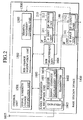
- Fig. 2 shows an exemplary configuration of a base station device 1400 that can be used for each one of the base station devices 1401-1406 of Fig. 1.
- This base station device 1400 of Fig. 2 comprises a control unit 1500 having a signal strength change notification unit 1501, a BER (Bit Error Rate) change notification unit 1502 and a terminal movement control unit 1503; a radio transmission and reception unit 1600 having a receiver 1601 that contains a signal strength measurement unit 1604, a transmitter 1602, and a duplexer 1603 for enabling the receiver 1601 and the transmitter 1602 to commonly use an antenna 1605; a BER measurement unit 1606; an IP unit 210 having an IP input unit 211 and an IP output unit 212; and an IF (interface) unit 140 having an IF input unit 141 and an IF output unit 142.
- solid lines indicate data flows while dashed lines indicate control flows.
- the signal strength measurement unit 1604 measures a received signal strength for each radio terminal device 1801-1804, and notifies the measured signal strength regularly to the control unit 1500.
- the BER measurement unit 1606 measures the BER of signals flowing from the receiver 1601 to the IF output unit 142 for each radio terminal device 1801-1804, and notifies the measured BER regularly to the control unit 1500.
- the received signal strength and the BER are Just examples of information indicating a radio communication state between the radio terminal device and the radio base station device.
- the signal strength change notification unit 1501 of the control unit 1500 gives a message to the IP output unit 212, where the message has the router device 1301 as its destination and contains the received signal strength for each radio terminal device 1801-1804 obtained by the signal strength measurement unit 1604 and an identifier of a corresponding radio terminal device 1801-1804.
- the BER change notification unit 1502 of the control unit 1500 gives a message to the IP output unit 212, where the message has the router device 1301 as its destination and contains the BER for each radio terminal device 1801-1804 obtained by the BER measurement unit 1606 and an identifier of a corresponding radio terminal device 1801-1804.
- an IP address allocated to each radio terminal device 1801-1804 can be used, for example.
- a new ICMP (Internet Control Message Protocol) message may be defined. Namely, as an ICMP message for notifying an information indicating the radio communication state such as the received signal strength or the BER and the identifier of the radio terminal device, new type and code can be allocated and a format for information content (the received signal strength or the BER and the identifier of the radio terminal device) can be defined. This message may be notified from the base station device 1400 to the router device 1301 either regularly or only when the received signal strength or the BER exceeds a prescribed threshold.
- ICMP Internet Control Message Protocol
- Fig. 3 shows an exemplary configuration of the router device 1301 of Fig. 1.
- This router device 1301 of Fig. 3 generally comprises a plurality (only two are shown in Fig. 3) of wire IF units 100, 110 which are connected with the wire network 1101 and the gateway devices 501-503 respectively; a plurality (only two are shown in Fig. 3) of radio IF units 120, 130 which are connected with the base station devices 1401-1406 respectively; and an IP unit 200.
- Each wire IF unit 100, 110 comprises a wire IF input unit 101, 111 and a wire IF output unit 102, 112, while each radio IF unit 120, 130 comprises a radio IF input unit 121, 131 and a radio IF output unit 122, 132.
- the IP unit 200 comprises an IP input unit 201 having a datagram filter 205, an IP output unit 202, an IP relay unit 203 storing a correspondence table 206, and a mobile control unit 204.
- the message (ICMP message for example) for notifying the radio communication state that is transmitted from the base station device reaches to the IP input unit 201 via the radio IF input unit 121 or 131. Then, the IP input unit 201 recognizes that this message is an ICMP message for notifying the radio communication state (which can be identified by the type and code of ICMP) by using the datagram filter 205. Then, the IP input unit 201 also recognizes that it is a message (IP datagram) to be transferred to one of the gateway devices 501-503 which is relaying the transport layer connection terminated at the radio terminal device as identified by the identifier contained in that message, and gives it to the IP relay unit 203.
- IP datagram IP datagram
- the correspondence table 206 of the IP relay unit 203 indicates a correspondence between IP addresses of the radio terminal devices 1801-1804 and IP addresses of the gateway devices 501-503 which are relaying the transport layer connections terminated at the radio terminal devices 1801-1804.
- This correspondence can be established as follows, for example.
- the terminal movement control unit 1503 of the base station device 1401-1406 notifies to the mobile control unit 204 of the router device 1301 that the radio terminal device 1801-1804 is newly discovered in one of the radio service areas 1701-1706 (including the case where the radio terminal device turns the power on there)
- the mobile control unit 204 sets that radio terminal device in correspondence to one of the gateway devices 501-503 according to a prescribed rule.
- the IP relay unit 203 obtains the IP address of one of the gateway devices 501-503 that corresponds to the IP address of the radio terminal device contained in that message, from the correspondence table 206. Then, the IP relay unit 203 writes this IP address of the gateway device into an IP header of that message as a new destination of that message, and gives this message to the IP output unit 202.
- the IP output unit 202 then transmits this message to one of the gateway devices 501-503 via the wire IF output unit 102 or 112 that corresponds to the destination of that message.
- the destination of the message entered into the IP input unit 201 is an address of the router device 1301 so that it should be given to the upper layer normally. Consequently, the above described processing at the IP relay unit 203 (the processing for specifying a gateway device that corresponds to the radio terminal device of the identifier contained in that message by referring to the correspondence table 206 and transferring that message to that identified gateway device) may be carried out at the upper layer. Namely, it is possible to provide a function for processing that message in the upper layer and give that message to this function instead of the IP relay unit 203.
- Fig. 4 shows an exemplary configuration of a gateway device 500 that can be used for each one of the gateway devices 501-503 of Fig. 1.
- This gateway device 500 of Fig. 4 generally comprises an IF unit 150, an IP unit 220, a TCP unit 300, a TCP relay unit 310 and a radio TCP unit 320.
- the IF unit 150 comprises an IF input unit 151 and an IF output unit 152 which are connected to the router device 1301.
- the IP unit 220 comprises an IP input unit 221 having a datagram filter 224, an IP output unit 222, an IP relay unit 223, and a radio communication state receiving processing unit 225.
- the TCP unit 300 comprises a TCP input unit 301 having a segment filter 303 and a TCP output unit 302.
- the radio TCP unit 320 comprises a radio TCP input unit 321 having a segment filter 323, a radio TCP output unit 322, and a radio communication state adaptation control unit 324.
- the TCP relay unit 310 comprises a converter 311 for converting the radio transport layer protocol into the wire transport layer protocol, and a converter 312 for converting the wire transport layer protocol into the radio transport layer protocol.
- the message transferred from the router device 1301 to the gateway device 500 reaches to the IP input unit 221 through the IF input unit 151 of the gateway device 500.
- the IP input unit 221 recognizes that the entered message is a message for notifying the radio communication state by using the datagram filter 224, and sends this message to the radio communication state receiving processing unit 225.
- the radio communication state receiving processing unit 225 extracts an identifier (IP address) of the radio terminal device and an information regarding the radio communication state (such as the received signal strength or the BER for example) contained in the message, and notifies them to the radio TCP unit 320.
- IP address an identifier
- the radio communication state receiving processing unit 225 extracts an identifier (IP address) of the radio terminal device and an information regarding the radio communication state (such as the received signal strength or the BER for example) contained in the message, and notifies them to the radio TCP unit 320.
- the radio communication state adaptation control unit 324 of the radio TCP unit 320 then adaptively changes the radio TCP operation according to that information regarding the radio communication state. For example, the maximum size of a radio TCP segment to be transmitted is made smaller when the BER becomes higher than a prescribed threshold (or when the received signal strength becomes lower than a prescribed threshold), and the maximum size of a radio TCP segment to be transmitted is made larger when the BER becomes lower than a prescribed threshold (or when the received signal strength becomes higher than a prescribed threshold).
- Such a transport layer connection control command (a command for changing the size of a TCP segment, for example) is applied to the radio TCP output unit 322 such that each radio TCP segment that is subsequently transmitted from the converter 312 of the TCP relay unit 310 will have its size changed to the size determined by the radio communication state adaptation control unit 324 at a time of output from the radio TCP output unit 322, and transmitted to the base station device through the IP output unit 222 and the IF output unit 152.
- the first embodiment is directed to the case where the router device 1301 sets the radio terminal device identified by the identifier contained in the message in correspondence to one of the plurality of gateway devices according to the message for notifying the radio communication state that is transmitted from one of the base station devices 1401-1406 to the router device 1301 (the case of specifying a gateway device that is a transfer target of the message for notifying the radio communication state).
- this second embodiment is directed to the case where the base station device 1401-1406 sets the radio terminal device in correspondence to one of the plurality of gateway devices.
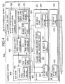
- Fig. 5 shows an exemplary configuration of a base station device 1400 according to this second embodiment, that can be used for each one of the base stations 1401-1406 of Fig. 1.
- the elements that are substantially the same as those of Fig. 2 are given the same reference numerals in Fig. 5 and only differences from Fig. 2 will be described. Namely, the configuration of Fig. 5 differs from that of Fig. 2 in that the control unit 1500 has a correspondence table 1504.
- the correspondence table 1504 indicates a correspondence between IP addresses of the radio terminal devices 1801-1804 and IP addresses of the gateway devices 501-503 which are relaying the transport layer connections terminated at the radio terminal devices 1801-1804.
- This correspondence can be established as follows, for example.
- the router device 1301 already has this correspondence in the correspondence table 206 by the procedure described in the first embodiment.
- the mobile control unit 204 of the router device 1301 searches for an identifier (IP address) of one of the gateway devices 501-503 that is relaying the transport layer connection terminated at the radio terminal device as identified by the identifier (IP address) contained in that received message, by referring to the correspondence table 206. Then, the mobile control unit 204 of the router device 1301 transmits a prescribed response message containing this searched out identifier of the gateway device to the base station device that transmitted the message for noting the discovery of the radio terminal device earlier.
- IP address IP address
- the response message from the router device 1301 is received through the IF input unit 141 and the IP input unit 211, and the identifier of the gateway device is extracted from that response message. Then, the terminal movement control unit 1503 registers a correspondence between that identifier of the gateway device and that radio terminal device in the correspondence table 1504.
- the signal strength change notification unit 1501 of the control unit 1500 generates a message containing the received signal strength for that radio terminal device obtained by the signal strength measurement unit 1604 and the identifier of that radio terminal device, and gives this message to the IP output unit 212.
- the signal strength change notification unit 1501 searches out the identifier (IP address) of the gateway device that corresponds to the identifier of that radio terminal device from the correspondence table 1504, and sets it as a destination of the generated message.
- the BER change notification unit 1502 of the control unit 1500 generates a message containing the BER for that radio terminal device obtained by the BER measurement unit 1606 and the identifier of that radio terminal device, and gives this message to the IP output unit 212.
- the BER change notification unit 1502 searches out the identifier (IP address) of the gateway device that corresponds to the identifier of that radio terminal device from the correspondence table 1504, and sets it as a destination of the generated message.
- the router device 1301 When such a message is transmitted to the router device 1301 through the IP output unit 212 and the IF output unit 142, the router device 1301 handles it similarly as the usual IP packet by carrying out the routing to one of the gateway devices 501-503 that is specified by the IP address contained in the IP packet.
- the operation of the gateway device 501-503 that received this message is the same as in the first embodiment described above.
- the first and second embodiments are directed to the case where the gateway device 501-503 carries out the radio TCP control by utilizing the message for notifying the radio communication state that is transmitted from the base station device 1401-1406 or the router device 1301.
- this third embodiment is directed to the case of utilizing a home location register to be provided in a radio network will be described.
- the base station device has a configuration of Fig. 5 described above.
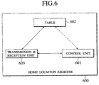
- Fig. 6 shows an exemplary configuration of the home location register 600, which comprises a control unit 601, a radio state information management table 602, and a transmission and reception unit 603.
- Fig. 7 shows an exemplary content of the radio state information management table 602 managed by the home location register 600 of Fig. 6.
- the home location register 1303 manages a registered radio terminal and a base station that accommodates that radio terminal, and an information on a radio communication state between that radio terminal and that base station, using the table content as shown in Fig. 7 in the radio state information management table 602.
- the signal strength change notification unit 1501 of the control unit 1500 in the radio base station 1401-1406 generates a message containing the received signal strength for that radio terminal device obtained by the signal strength measurement unit 1604 and the identifier of that radio terminal device, and gives this message to the IP output unit 212.
- the signal strength change notification unit 1501 searches out the identifier (IP address) of that radio terminal device from the correspondence table 1504, and sets it as a part of data of the generated message. Also, the address of the home location register 600 is set as a destination address of the generated message.
- the BER change notification unit 1502 of the control unit 1500 generates a message containing the BER for that radio terminal device obtained by the BER measurement unit 1606 and the identifier of that radio terminal device, and gives this message to the IP output unit 212.
- the BER change notification unit 1502 searches out the identifier (IP address) of that radio terminal device from the correspondence table 1504, and sets it as a part of data of the generated message. Also, the address of the home location register 600 is set as a destination address of the generated message.
- the router device 1301 When such a message is transmitted to the router device 1301 through the IP output unit 212 and the IF output unit 142, the router device 1301 handles it similarly as the usual IP packet by carrying out the routing to the home location register 600 that is specified by the IP address contained in the IP packet.
- the control unit 601 of the home location register 600 takes out the radio terminal identifier and the radio communication state information from that message, and add them to the radio state information management table 602.
- the control unit 601 takes out the radio communication state of the corresponding radio terminal from the radio state information management table 602, forms a packet containing that information, and transmits that packet to the gateway device 501-503.
- the operation of the gateway device 501-503 that received this message is the same as in the first embodiment described above.
- the wire terminal 1001 connected to the wire network 1101 is carrying out communications with the radio terminal 1802 through the gateway device 501.
- the radio communication state adaptation control unit 324 in the radio TCP unit 320 of the gateway device 501 sets the radio keep-alive timer (not shown).
- the time set for this timer is sufficiently shorter than the keep-alive timer usually utilized in the TCP layer.
- the radio communication state adaptation control unit 324 carries out the operation to disconnect a connection between the wire terminal 1001 and the radio terminal 1802.
- the radio communication state adaptation control unit 324 transmits a packet requesting the radio terminal 1802 to carry out the processing for disconnecting the connection.
- the radio communication state adaptation control unit 324 resets the radio keep-alive timer, while transmitting a signal requesting the radio TCP output unit 322 to reset a re-transmission timer 325 and re-transmit a re-transmission packet immediately.
- Fig. 8 shows an exemplary configuration of a radio terminal device 1800 that can be used for each one of the radio terminal devices 1801-1804 of Fig. 1.
- This radio terminal device 1800 of Fig. 8 comprises a communication state monitoring unit 704 and a TCP unit 700 that contains a control unit 701 for controlling the TCP layer, a TCP output unit 702, a TCP output unit 703, and a radio keep-alive timer 705.
- the communication state monitoring unit 704 is monitoring whether a link to the base station is connected or not, and notifies the monitored state to the control unit 701 of the TCP unit 700.
- the wire terminal 1001 connected to the wire network 1101 is carrying out communications with the radio terminal 1802 through the gateway device 501.
- the control unit 701 in the TCP unit 700 of the radio terminal device 1802 sets the radio keep-alive timer 705.
- the time set for this timer is sufficiently shorter than the keep-alive timer usually utilized in the TCP layer.
- the control unit 701 carries out the operation to disconnect the connection with the wire terminal 1001.
- the control unit 701 transmits a packet requesting the gateway device 501 to carry out the processing for disconnecting the connection.
- the control unit 701 resets the radio keep-alive timer 705, while transmitting a signal requesting the TCP output unit 702 to reset a re-transmission timer 706 and re-transmit a re-transmission packet immediately.
- the present invention it is possible to improve the performance of communications utilizing the transport layer connection provided via a radio network, by enabling a control of the transport layer connection according to the radio communication state and property of the radio terminal, without changing implementation of the transport layer of a terminal connected to a wire network.
Landscapes
- Engineering & Computer Science (AREA)
- Computer Networks & Wireless Communication (AREA)
- Signal Processing (AREA)
- Computer Security & Cryptography (AREA)
- Mobile Radio Communication Systems (AREA)
- Data Exchanges In Wide-Area Networks (AREA)
Claims (8)
- Dispositif formant passerelle (500) pour le transfert d'une connexion de couche de transport se terminant au niveau d'un dispositif terminal radio (1801-1804) par l'intermédiaire d'un dispositif formant routeur (1301) pour l'exécution d'un transfert de données entre le dispositif terminal radio (1801-1804) et un dispositif terminal câblé (1001-1003), le dispositif formant passerelle (500) étant prévu séparément du dispositif formant routeur (1301) en correspondance avec des connexions de couches de transport se terminant au niveau de dispositifs terminaux radio (1001-1003) et comprenant :une unité de transfert (150) configurée pour émettre et recevoir une information de commande respective; etune unité de conversion (310) configurée pour réaliser la conversion bidirectionnelle d'un premier protocole de couche de transport utilisé pour des communications avec un réseau radio et un second protocole de couche de transport utilisé pour des communications à l'intérieur d'un réseau câblé, dans le cas de l'exécution de communications entre le dispositif terminal radio (1801-1804) logé dans le réseau radio et le dispositif terminal câblé (1001-1003) logé dans le réseau câblé;
caractérisé par
une unité de commande (324) configurée de manière à commander de façon adaptative une caractéristique de fonctionnement d'une connexion dans le premier protocole de couche de transport conformément à une information concernant un état de communication radio du dispositif terminal radio (1801-1804). - Dispositif formant passerelle selon la revendication 1, dans lequel l'unité de commande (324) est configurée de manière à recevoir l'information concernant l'état de communication radio du dispositif terminal radio (1801-1804) à partir d'un dispositif de station de base radio (1401-1406) couvrant une zone de service radio, dans laquelle est situé le dispositif terminal radio (1801-1804).
- Dispositif formant passerelle selon la revendication 1, dans lequel l'unité de commande (324) est configurée de manière à recevoir l'information concernant l'état de communication radio du dispositif terminal radio (1801-1804) à partir d'un registre d'emplacements domestiques (600) pour exécuter au moins l'enregistrement et la gestion du dispositif terminal radio (1801-1804).
- Dispositif formant passerelle selon la revendication 1, comprenant en outre :une unité de déconnexion pour déconnecter une connexion dans le second protocole de couche de transport, lorsque des communications avec le dispositif terminal radio ne sont pas reprises au cours d'un intervalle de temps prescrit après la réception de l'information concernant l'état de communication radio du dispositif terminal radio qui contient une information indiquant que des communications avec le dispositif terminal radio sont interrompues.
- Dispositif formant passerelle selon la revendication 4, dans lequel l'unité de déconnexion est également configuré de manière à déconnecter une connexion dans le premier protocole de couche de transport utilisé par le dispositif terminal radio (1801-1804), qui a exécuté des communications en utilisant la connexion dans le second protocole de couche de transport, lorsqu'un paquet arrive du dispositif terminal radio (1801-1804) une fois que la connexion dans le second protocole de couche de transport est déconnectée.
- Dispositif formant passerelle selon la revendication 1, comprenant en outre :une minuterie de réémission pour indiquer un instant pour la réémission d'un paquet; etune unité pour ramener à l'état initial la minuterie de rémission et pour effectuer immédiatement une réémission dudit paquet devant être réémis, lors de la réception de l'information concernant l'état de communication radio du dispositif terminal radio qui contient un signal indiquant que des communications avec le dispositif terminal radio sont reprises.
- Dispositif formant routeur (1301), qui est connecté à une pluralité de dispositifs formant stations de base radio (1401-1406) pour loger un dispositif terminal radio (1801-1804) situé dans des zones de service radio, et un réseau câblé auquel un dispositif terminal câblé (1001-1003) est connecté, pour l'exécution d'un transfert de données entre le dispositif terminal radio (1801-1804) et le dispositif terminal câblé (1001-1003) moyennant l'utilisation d'une pluralité de dispositifs formant passerelles (501-503) pour retransmettre une connexion de couche de transport se terminant au niveau du dispositif terminal radio (1801-1804), le dispositif formant routeur (1301) étant caractérisé par :une unité (203) de réglage de correspondance configurée de manière à régler le dispositif terminal radio (1801-1804) en correspondance avec une pluralité de dispositifs formant passerelles (501-503) pour commander de façon adaptative une caractéristique de fonctionnement d'une connexion de couche de transport pour les communications radio du dispositif radio mobile (1801-1804) conformément à un état de communication radio du dispositif terminal radio (1801-1804); etune unité de transfert (204) configurée de manière à recevoir, à partir d'un dispositif de station de base radio (1401-1406) dans la zone de service radio duquel est situé le dispositif terminal radio (1801-1804), un paquet qui contient au moins un identifiant du dispositif terminal radio (1801-1804) et une information concernant l'état de communication radio du dispositif terminal radio (1801-1804) et le transfert dudit paquet à un dispositif formant passerelle (501-503) qui est réglé en correspondance avec le dispositif terminal radio (1801-1804) au moyen de l'unité de réglage de correspondance (203).
- Dispositif de station de base radio (1400) pour la mise en oeuvre d'un transfert de données entre un dispositif terminal radio (1801-1804) et un dispositif terminal câblé (1001-1003) moyennant l'utilisation d'une pluralité de dispositifs formant passerelles pour le transfert d'une connexion de couche de transport se terminant dans le dispositif terminal radio (1801-1804), le dispositif de station de base radio comprenant :une unité de traitement (1500) configurée de manière à exécuter un traitement de station de base nécessaire pour loger un dispositif terminal radio (1801-1804) situé dans une zone de service radio;une unité de notification (1502) configurée de manière à notifier une information concernant un état de communication radio du dispositif terminal radio (1801-1804) situé dans la zone de service radio, à l'un d'un routeur (1301), d'une passerelle (500) et d'un registre d'emplacements domestiques (600); et
caractérisé par
une unité de réglage de correspondance (1504) configurée de manière à régler le dispositif terminal radio (1801-1804) situé dans la zone de service radio en correspondance avec l'un d'une pluralité de dispositifs formant passerelles (501-503) pour commander de façon adaptative une caractéristique de fonctionnement d'une connexion de couche de transport pour des communications radio du dispositif terminal radio (1801-1804) conformément à l'état de communication radio du dispositif terminal radio (1801-1804).
Applications Claiming Priority (9)
| Application Number | Priority Date | Filing Date | Title |
|---|---|---|---|
| JP257153/97 | 1997-09-22 | ||
| JP25715397 | 1997-09-22 | ||
| JP25715397 | 1997-09-22 | ||
| JP26442297 | 1997-09-29 | ||
| JP26442297 | 1997-09-29 | ||
| JP264422/97 | 1997-09-29 | ||
| JP23338998 | 1998-08-20 | ||
| JP23338998A JP3949288B2 (ja) | 1997-09-22 | 1998-08-20 | ゲートウェイ装置及び無線端末装置 |
| JP233389/98 | 1998-08-20 |
Publications (3)
| Publication Number | Publication Date |
|---|---|
| EP0903906A2 EP0903906A2 (fr) | 1999-03-24 |
| EP0903906A3 EP0903906A3 (fr) | 2001-04-11 |
| EP0903906B1 true EP0903906B1 (fr) | 2006-03-01 |
Family
ID=27331986
Family Applications (1)
| Application Number | Title | Priority Date | Filing Date |
|---|---|---|---|
| EP98307677A Expired - Lifetime EP0903906B1 (fr) | 1997-09-22 | 1998-09-22 | Dispositifs de contrôle adaptatif des connexions de transport entre des terminaux mobiles et fixes |
Country Status (4)
| Country | Link |
|---|---|
| US (2) | US6418128B1 (fr) |
| EP (1) | EP0903906B1 (fr) |
| JP (1) | JP3949288B2 (fr) |
| DE (1) | DE69833615T2 (fr) |
Cited By (1)
| Publication number | Priority date | Publication date | Assignee | Title |
|---|---|---|---|---|
| US9480074B2 (en) | 2004-07-23 | 2016-10-25 | Qualcomm Incorporated | Enabling quick and easy demodulation |
Families Citing this family (45)
| Publication number | Priority date | Publication date | Assignee | Title |
|---|---|---|---|---|
| JP3239859B2 (ja) * | 1998-09-24 | 2001-12-17 | 日本電気株式会社 | 移動体通信システム及びその通信方法 |
| EP1045551A3 (fr) * | 1999-04-15 | 2003-06-18 | Lucent Technologies Inc. | Méthode de transmission entre des réseaux de communications et des systèmes de communication sans fil |
| SE516871C2 (sv) * | 1999-06-23 | 2002-03-12 | Teracom Ab | Metod för flödesstyrning i ett datakommunikationsnät |
| US6546046B1 (en) * | 1999-11-17 | 2003-04-08 | Conexant Systems, Inc. | DSL pre-synchronization auto baud |
| DE19956318A1 (de) * | 1999-11-23 | 2001-05-31 | Bosch Gmbh Robert | Verfahren zur Steuerung |
| US7003571B1 (en) * | 2000-01-31 | 2006-02-21 | Telecommunication Systems Corporation Of Maryland | System and method for re-directing requests from browsers for communication over non-IP based networks |
| US8090856B1 (en) | 2000-01-31 | 2012-01-03 | Telecommunication Systems, Inc. | Intelligent messaging network server interconnection |
| US7623447B1 (en) | 2000-04-10 | 2009-11-24 | Nokia Corporation | Telephony services in mobile IP networks |
| US7298697B2 (en) * | 2000-04-10 | 2007-11-20 | Nokia Corporation | Setting a communication channel |
| JP3730480B2 (ja) | 2000-05-23 | 2006-01-05 | 株式会社東芝 | ゲートウェイ装置 |
| JP2001345829A (ja) * | 2000-06-06 | 2001-12-14 | Ntt Communications Kk | 狭域通信システム |
| DE10038557B4 (de) * | 2000-08-03 | 2005-12-15 | Siemens Ag | System und Verfahren zur Übertragung von Daten über Datennetze, insbesondere Internet, mit asynchroner Datenverbindung |
| US20020080774A1 (en) * | 2000-09-08 | 2002-06-27 | Avtec Systems, Inc. | Methods and systems for interfacing wired/wireless hybrid systems |
| US20020031104A1 (en) * | 2000-09-08 | 2002-03-14 | Avtec Systems, Inc. | Methods and systems for interfacing wired/wireless hybrid systems |
| BR0017350A (pt) | 2000-10-09 | 2003-10-28 | Nokia Corp | Método para liberar pelo menos uma parte de uma conexão em uma rede de comunicação de duas camadas, e, sistema de comunicação |
| US7483983B1 (en) | 2000-11-13 | 2009-01-27 | Telecommunication Systems, Inc. | Method and system for deploying content to wireless devices |
| JP3814185B2 (ja) | 2000-11-13 | 2006-08-23 | 松下電器産業株式会社 | 基地局装置、移動通信端末装置、及びそれらを用いた無線アクセスシステム |
| JP3693239B2 (ja) * | 2001-03-09 | 2005-09-07 | 株式会社エヌ・ティ・ティ・ドコモ | 情報提供方法、移動通信システム及び通信装置 |
| US7136364B2 (en) * | 2001-03-29 | 2006-11-14 | Intel Corporation | Maintaining a reliable link |
| US7054945B2 (en) | 2001-04-09 | 2006-05-30 | Nokia Corporation | Technique for providing announcements in mobile-originated calls |
| US6950437B2 (en) * | 2001-04-24 | 2005-09-27 | Atitania Ltd. | System and method for transmission of information between locations on a computer network with the use of unique packets |
| US6975595B2 (en) * | 2001-04-24 | 2005-12-13 | Atttania Ltd. | Method and apparatus for monitoring and logging the operation of a distributed processing system |
| JP2003110622A (ja) * | 2001-07-24 | 2003-04-11 | Ntt Docomo Inc | コネクション解放方法、リンク切断通知方法、中継装置、通信装置、交換機、プログラムおよび記録媒体 |
| JP3923835B2 (ja) * | 2001-07-24 | 2007-06-06 | 株式会社エヌ・ティ・ティ・ドコモ | 通信システム、ゲートウェイ、データ中継方法、プログラムおよび記録媒体 |
| US20030040279A1 (en) * | 2001-08-22 | 2003-02-27 | Ballweg Alan R. | Wireless thermostat system |
| US7788381B2 (en) * | 2001-09-17 | 2010-08-31 | Foundry Networks, Inc. | System and method for router keep-alive control |
| JP2004180244A (ja) * | 2002-11-29 | 2004-06-24 | Alps Electric Co Ltd | 回線接続復旧方法および回線接続復旧プログラム |
| WO2004100485A1 (fr) * | 2003-05-07 | 2004-11-18 | Research In Motion Limited | Procedes et appareil visant a reduire le trafic ip de pousser non distribuable dans un reseau sans fil |
| JP4339853B2 (ja) * | 2003-08-19 | 2009-10-07 | 株式会社エヌ・ティ・ティ・ドコモ | アドホックネットワークにおける伝送情報の正確な制御 |
| US8432803B2 (en) | 2004-07-21 | 2013-04-30 | Qualcomm Incorporated | Method of providing a gap indication during a sticky assignment |
| US8477710B2 (en) * | 2004-07-21 | 2013-07-02 | Qualcomm Incorporated | Method of providing a gap indication during a sticky assignment |
| US7512714B2 (en) * | 2004-08-31 | 2009-03-31 | Honeywell International Inc. | System and method for transmitting ACARS messages over a TCP/IP data communication link |
| JP4407556B2 (ja) * | 2005-03-29 | 2010-02-03 | 日本電気株式会社 | セッション中継装置、セッション中継方法およびプログラム |
| US8121069B2 (en) | 2005-09-27 | 2012-02-21 | Research In Motion Limited | Adaptive data delivery |
| DE602005014396D1 (de) | 2005-09-27 | 2009-06-18 | Research In Motion Ltd | Adaptive Datenzustellung |
| US8761747B2 (en) * | 2007-04-30 | 2014-06-24 | Samsung Electronics Co., Ltd. | Universal browser |
| US8238827B2 (en) * | 2007-06-15 | 2012-08-07 | Fujitsu Toshiba Mobile Communications Limited | Information processing apparatus |
| US8099505B2 (en) * | 2008-03-26 | 2012-01-17 | Microsoft Corporation | Aggregating connection maintenance to optimize resource consumption |
| RU2371852C1 (ru) * | 2008-07-10 | 2009-10-27 | Федеральное государственное учреждение 16 Центральный научно-исследовательский испытательный институт Министерства обороны Российской Федерации имени маршала войск связи А.И. Белова | Система радиосвязи с ретранслятором |
| US8503300B2 (en) * | 2008-10-17 | 2013-08-06 | Verizon Patent And Licensing Inc. | Efficient messaging over internet protocol |
| US20110243064A1 (en) * | 2010-03-31 | 2011-10-06 | By Light Professional IT Services | Systems, methods and devices for convergent communications using remote keying |
| US9426690B2 (en) | 2010-12-07 | 2016-08-23 | Telefonaktiebolaget Lm Ericsson (Publ) | Method for enabling traffic acceleration in a mobile telecommunication network |
| US9191862B2 (en) | 2011-09-06 | 2015-11-17 | Qualcomm Incorporated | Method and apparatus for adjusting TCP RTO when transiting zones of high wireless connectivity |
| WO2013052002A2 (fr) * | 2011-10-05 | 2013-04-11 | Telefonaktiebolaget L M Ericsson (Publ) | Libération de tcp efficace radio |
| EP2648450B1 (fr) * | 2012-04-03 | 2015-08-19 | Alcatel Lucent | Amélioration de transfert pour le trafic de couche d'application d'équipement utilisateur sur un réseau mobile |
Family Cites Families (19)
| Publication number | Priority date | Publication date | Assignee | Title |
|---|---|---|---|---|
| JPH0329430A (ja) | 1989-06-26 | 1991-02-07 | Iwatsu Electric Co Ltd | 移動体通信の時間分割通信方法 |
| US5793843A (en) * | 1989-10-31 | 1998-08-11 | Intelligence Technology Corporation | Method and apparatus for transmission of data and voice |
| US5224098A (en) * | 1991-07-17 | 1993-06-29 | International Business Machines Corporation | Compensation for mismatched transport protocols in a data communications network |
| JPH0583157A (ja) | 1991-09-20 | 1993-04-02 | Nec Eng Ltd | 無線通信監視装置および無線通信監視システム |
| US6400702B1 (en) * | 1991-10-01 | 2002-06-04 | Intermec Ip Corp. | Radio frequency local area network |
| US5504746A (en) * | 1991-10-01 | 1996-04-02 | Norand Corporation | Radio frequency local area network |
| US5826198A (en) * | 1992-01-13 | 1998-10-20 | Microcom Systems, Inc. | Transmission of data over a radio frequency channel |
| US5457680A (en) | 1993-05-18 | 1995-10-10 | International Business Machines Corporation | Data gateway for mobile data radio terminals in a data communication network |
| JP3250129B2 (ja) | 1994-07-29 | 2002-01-28 | 日本電信電話株式会社 | パケットサービス無中断ハンドオーバ方法 |
| US5633868A (en) | 1994-10-17 | 1997-05-27 | Lucent Technologies Inc. | Virtual circuit management in cellular telecommunications |
| US6067534A (en) * | 1994-12-23 | 2000-05-23 | Nokia Mobile Phones Ltd. | Method and equipment for the control of a data transfer connection |
| JP2944459B2 (ja) | 1995-04-07 | 1999-09-06 | 日本電気株式会社 | 移動通信システムにおける送信電力制御方法 |
| WO1997008838A2 (fr) | 1995-08-14 | 1997-03-06 | Ericsson Inc. | Procede et equipement permettant de modifier un en-tete normalise de couche de protocole inter-reseaux |
| JPH0955764A (ja) | 1995-08-14 | 1997-02-25 | Nippon Telegr & Teleph Corp <Ntt> | 無線パケット通信方法 |
| FI105740B (fi) | 1995-09-29 | 2000-09-29 | Nokia Mobile Phones Ltd | Toimistoviestintäjärjestelmä |
| FI101508B1 (fi) | 1995-09-29 | 1998-06-30 | Nokia Mobile Phones Ltd | Kiinteän viestintäverkon solukkolaajennus |
| US5933784A (en) * | 1996-06-28 | 1999-08-03 | Synacom Technology, Inc. | Signaling gateway system and method |
| US5894478A (en) * | 1996-07-24 | 1999-04-13 | Lucent Technologies Inc. | Protocol converter and router for multi-mode wireless data communications |
| US5911123A (en) * | 1996-07-31 | 1999-06-08 | Siemens Information And Communications Networks, Inc. | System and method for providing wireless connections for single-premises digital telephones |
-
1998
- 1998-08-20 JP JP23338998A patent/JP3949288B2/ja not_active Expired - Fee Related
- 1998-09-21 US US09/157,616 patent/US6418128B1/en not_active Expired - Fee Related
- 1998-09-22 EP EP98307677A patent/EP0903906B1/fr not_active Expired - Lifetime
- 1998-09-22 DE DE69833615T patent/DE69833615T2/de not_active Expired - Lifetime
-
2002
- 2002-07-08 US US10/189,502 patent/US7269148B2/en not_active Expired - Fee Related
Cited By (1)
| Publication number | Priority date | Publication date | Assignee | Title |
|---|---|---|---|---|
| US9480074B2 (en) | 2004-07-23 | 2016-10-25 | Qualcomm Incorporated | Enabling quick and easy demodulation |
Also Published As
| Publication number | Publication date |
|---|---|
| EP0903906A2 (fr) | 1999-03-24 |
| US7269148B2 (en) | 2007-09-11 |
| DE69833615T2 (de) | 2006-08-10 |
| DE69833615D1 (de) | 2006-04-27 |
| US6418128B1 (en) | 2002-07-09 |
| US20020186680A1 (en) | 2002-12-12 |
| JPH11163946A (ja) | 1999-06-18 |
| JP3949288B2 (ja) | 2007-07-25 |
| EP0903906A3 (fr) | 2001-04-11 |
Similar Documents
| Publication | Publication Date | Title |
|---|---|---|
| US7269148B2 (en) | Scheme for adaptive control of transport layer connection in communications via radio and wire networks | |
| EP0903905B1 (fr) | Dispositif pour la communication fiable par les réseaux radio et cablés utilisant des connections à la couche de transport | |
| JP2838998B2 (ja) | 移動端末及び移動対応ネットワーク | |
| JP4050462B2 (ja) | 無線通信システムにおけるデータの経路設定誤りを防止する方法及び装置 | |
| CN100413287C (zh) | 蜂窝空中接口的ad-hoc扩展 | |
| US8189531B2 (en) | Wireless communication system, wireless base station, and wireless communication control method | |
| US20070147299A1 (en) | Wireless transmission device | |
| KR20020059678A (ko) | 네트워크에서 이동성을 제공하기 위한 방법 및 장치 | |
| EP1068692A1 (fr) | Dispositif et procede de communication sans fil de donnees en paquets | |
| JP2009200689A (ja) | 通信システム及び通信処理方法並びにノード | |
| US7532593B2 (en) | Radio LAN system, diversity apparatus, and radio LAN terminal | |
| WO2003015315A1 (fr) | Systeme support d'un mecanisme de transfert/itinerance dans un reseau sans fil a courte distance utilisant bluetooth | |
| JP4256211B2 (ja) | データリンク層のトリガプロトコル | |
| JP2006101428A (ja) | 無線ネットワークの制御装置及び制御方法、制御プログラム並びに記録媒体 | |
| US7002959B2 (en) | Packet communication method, node apparatus and packet communication system | |
| WO2020221202A1 (fr) | Procédé de traitement de données, appareil de communication, et système | |
| US9344934B2 (en) | Method and apparatus for reducing latency during wireless connectivity changes | |
| WO2002003147A2 (fr) | Procede de detection de paquets invalides au moyen de la re-ecriture des identificateurs de transaction | |
| US7957281B2 (en) | Method for interworking between access control router and position determination entity in position recognition system based on portable internet and system therefor | |
| US20090180437A1 (en) | Communication apparatus and handover method | |
| JP4487058B2 (ja) | 無線通信システム及び無線通信方法 | |
| CN115333992B (zh) | 基于标准prp协议的链路资源优化方法 | |
| JP2006148579A (ja) | 通信方法およびネットワークシステム | |
| KR100558116B1 (ko) | 디지털 셀룰러 기반 무선 원격제어 시스템 | |
| JP5000228B2 (ja) | 無線通信装置 |
Legal Events
| Date | Code | Title | Description |
|---|---|---|---|
| PUAI | Public reference made under article 153(3) epc to a published international application that has entered the european phase |
Free format text: ORIGINAL CODE: 0009012 |
|
| 17P | Request for examination filed |
Effective date: 19981016 |
|
| AK | Designated contracting states |
Kind code of ref document: A2 Designated state(s): DE FR GB SE |
|
| AX | Request for extension of the european patent |
Free format text: AL;LT;LV;MK;RO;SI |
|
| RIC1 | Information provided on ipc code assigned before grant |
Free format text: 7H 04L 29/06 A, 7H 04L 12/66 B, 7H 04L 12/28 B, 7H 04L 29/08 B |
|
| PUAL | Search report despatched |
Free format text: ORIGINAL CODE: 0009013 |
|
| AK | Designated contracting states |
Kind code of ref document: A3 Designated state(s): AT BE CH CY DE DK ES FI FR GB GR IE IT LI LU MC NL PT SE |
|
| AX | Request for extension of the european patent |
Free format text: AL;LT;LV;MK;RO;SI |
|
| AKX | Designation fees paid |
Free format text: DE FR GB SE |
|
| 17Q | First examination report despatched |
Effective date: 20040301 |
|
| GRAP | Despatch of communication of intention to grant a patent |
Free format text: ORIGINAL CODE: EPIDOSNIGR1 |
|
| RTI1 | Title (correction) |
Free format text: DEVICES FOR ADAPTIVE CONTROL OF TRANSPORT-LAYER CONNECTIONS BETWEEN MOBILE AND FIXED HOSTS |
|
| GRAS | Grant fee paid |
Free format text: ORIGINAL CODE: EPIDOSNIGR3 |
|
| GRAA | (expected) grant |
Free format text: ORIGINAL CODE: 0009210 |
|
| AK | Designated contracting states |
Kind code of ref document: B1 Designated state(s): DE FR GB SE |
|
| REG | Reference to a national code |
Ref country code: GB Ref legal event code: FG4D |
|
| REF | Corresponds to: |
Ref document number: 69833615 Country of ref document: DE Date of ref document: 20060427 Kind code of ref document: P |
|
| REG | Reference to a national code |
Ref country code: SE Ref legal event code: TRGR |
|
| ET | Fr: translation filed | ||
| PLBE | No opposition filed within time limit |
Free format text: ORIGINAL CODE: 0009261 |
|
| STAA | Information on the status of an ep patent application or granted ep patent |
Free format text: STATUS: NO OPPOSITION FILED WITHIN TIME LIMIT |
|
| 26N | No opposition filed |
Effective date: 20061204 |
|
| PGFP | Annual fee paid to national office [announced via postgrant information from national office to epo] |
Ref country code: DE Payment date: 20100915 Year of fee payment: 13 |
|
| PGFP | Annual fee paid to national office [announced via postgrant information from national office to epo] |
Ref country code: GB Payment date: 20110921 Year of fee payment: 14 Ref country code: SE Payment date: 20110913 Year of fee payment: 14 Ref country code: FR Payment date: 20110922 Year of fee payment: 14 |
|
| PG25 | Lapsed in a contracting state [announced via postgrant information from national office to epo] |
Ref country code: SE Free format text: LAPSE BECAUSE OF NON-PAYMENT OF DUE FEES Effective date: 20120923 |
|
| REG | Reference to a national code |
Ref country code: SE Ref legal event code: EUG |
|
| GBPC | Gb: european patent ceased through non-payment of renewal fee |
Effective date: 20120922 |
|
| REG | Reference to a national code |
Ref country code: FR Ref legal event code: ST Effective date: 20130531 |
|
| PG25 | Lapsed in a contracting state [announced via postgrant information from national office to epo] |
Ref country code: GB Free format text: LAPSE BECAUSE OF NON-PAYMENT OF DUE FEES Effective date: 20120922 Ref country code: DE Free format text: LAPSE BECAUSE OF NON-PAYMENT OF DUE FEES Effective date: 20130403 |
|
| PG25 | Lapsed in a contracting state [announced via postgrant information from national office to epo] |
Ref country code: FR Free format text: LAPSE BECAUSE OF NON-PAYMENT OF DUE FEES Effective date: 20121001 |
|
| REG | Reference to a national code |
Ref country code: DE Ref legal event code: R119 Ref document number: 69833615 Country of ref document: DE Effective date: 20130403 |