EP0903907A2 - Telefonendgerät mit Datenverarbeitungseinrichtung und System zur Unterstützung einer Kommunikation - Google Patents
Telefonendgerät mit Datenverarbeitungseinrichtung und System zur Unterstützung einer Kommunikation Download PDFInfo
- Publication number
- EP0903907A2 EP0903907A2 EP98302303A EP98302303A EP0903907A2 EP 0903907 A2 EP0903907 A2 EP 0903907A2 EP 98302303 A EP98302303 A EP 98302303A EP 98302303 A EP98302303 A EP 98302303A EP 0903907 A2 EP0903907 A2 EP 0903907A2
- Authority
- EP
- European Patent Office
- Prior art keywords
- telephone
- unit
- signal
- dtmf
- command signal
- Prior art date
- Legal status (The legal status is an assumption and is not a legal conclusion. Google has not performed a legal analysis and makes no representation as to the accuracy of the status listed.)
- Granted
Links
Images


Classifications
-
- H—ELECTRICITY
- H04—ELECTRIC COMMUNICATION TECHNIQUE
- H04M—TELEPHONIC COMMUNICATION
- H04M11/00—Telephonic communication systems specially adapted for combination with other electrical systems
- H04M11/007—Telephonic communication systems specially adapted for combination with other electrical systems with remote control systems
-
- H—ELECTRICITY
- H04—ELECTRIC COMMUNICATION TECHNIQUE
- H04M—TELEPHONIC COMMUNICATION
- H04M1/00—Substation equipment, e.g. for use by subscribers
- H04M1/64—Automatic arrangements for answering calls; Automatic arrangements for recording messages for absent subscribers; Arrangements for recording conversations
- H04M1/65—Recording arrangements for recording a message from the calling party
- H04M1/652—Means for playing back the recorded messages by remote control over a telephone line
-
- H—ELECTRICITY
- H04—ELECTRIC COMMUNICATION TECHNIQUE
- H04M—TELEPHONIC COMMUNICATION
- H04M1/00—Substation equipment, e.g. for use by subscribers
- H04M1/64—Automatic arrangements for answering calls; Automatic arrangements for recording messages for absent subscribers; Arrangements for recording conversations
- H04M1/65—Recording arrangements for recording a message from the calling party
- H04M1/656—Recording arrangements for recording a message from the calling party for recording conversations
-
- H—ELECTRICITY
- H04—ELECTRIC COMMUNICATION TECHNIQUE
- H04M—TELEPHONIC COMMUNICATION
- H04M1/00—Substation equipment, e.g. for use by subscribers
- H04M1/82—Line monitoring circuits for call progress or status discrimination
Definitions
- the present invention relates to a communication support system which is adapted to connect a telephone unit through a communication control device to a data processing device and adapted to connect a telephone network to the communication control device, when the user transmits a command signal from the telephone unit to the data processing device to obtain a computer-assisted telephone service from the data processing device. Further, the present invention relates to a computer readable medium which stores program code instructions for causing a processor to execute a telephone service processing in response to a command signal sent by the telephone unit.
- a conventional communication support system which provides existing telephone services by executing an application program installed in the system is known.
- the conventional communication support system provides the telephone services only when the user locally operates an input device (such as a keyboard or a mouse) of a personal computer. That is, when one of the telephone services is obtained from the conventional communication support system, the user must be located in front of the personal computer and locally operate the input device of the personal computer.
- FIG. 20 shows such a conventional communication support system.
- an existing telephone unit 301 is connected through the line unit 303 to the data processing device 304, and the telephone unit 301 is connected through the line unit 303 to a telephone network 302.
- the data processing device 304 is, for example, a personal computer.
- the telephone network 302 is, for example, a public switched telephone network.
- a voice input/output unit 305, a dialing unit 306 and a signal detection unit 307 are connected to the line unit 303. Further, a personal-computer (PC) interface unit 308 is provided between the data processing device 304 and the units 305, 306 and 307.
- PC personal-computer
- the voice input/output unit 305 supplies a voice signal sent from one of the telephone unit 301 and the telephone network 302, to the data processing device 304 via the PC interface unit 308, and supplies a voice signal derived from digital data stored in the data processing device 304, to one of the telephone unit 301 and the telephone network 302.
- the dialing unit 306 provides an existing dialing function to transmit a call to a destination terminal over the telephone network 302 according to a telephone number input by an input device (such as a keyboard or a mouse) of the data processing device 304.
- the signal detection unit 307 detects various signals sent from a telephone line, such as a busy tone signal, a ring tone signal, a ring back tone signal, an on-hook signal, and an off-hook signal.
- telephone services are provided by an existing telephone service application program executed by the data processing device (or the personal computer).
- Such telephone services include, for example, voice recording and playback, file transmission, and telephone number entry.
- the application program installed in the data processing device 304 is executed.
- the user inputs the telephone number of the destination terminal and presses a dialing button on a monitor of the data processing device 304 by manipulating the keyboard or the mouse of the data processing device 304.
- the user goes to the location of the telephone unit 301 apart from the data processing device 304, and lifts a handset of the telephone unit 301.
- the off-hook signal from the telephone unit 301 is detected by the signal detection unit 307.
- the telephone unit 301 is connected to the telephone network 302 (or the destination terminal) by the line unit 303, and this enables the user of the telephone unit 1 to communicate with a person of the destination terminal over the telephone network 302 by voice.
- a voice recording function as one of the telephone services, is obtained by executing the application program in the data processing device 304
- the user of the data processing device 304 presses a recording start button on the monitor by operating the input device of the data processing device 304.
- the data processing device 304 acquires voice data from the telephone unit 301 or the telephone network 302 through the voice input/output unit 305.
- the application program in the data processing device 304 converts the voice data into digital data in a computer-readable format and stores the digital data in a memory of the data processing device 304.
- the application program continues to provide the voice recording until a recording end button on the monitor is pressed by the user.
- a playback function as one of the telephone services, is obtained by executing the application program in the data processing device 304
- the user of the data processing device 304 presses a playback start button on the monitor by operating the input device.
- the application program in the data processing device 304 converts the digital data stored in the memory of the device 304 into voice data, and supplies the voice data to the voice input/output unit 305.
- a voice signal is derived from the voice data by the voice input/output unit 305, and the voice signal is supplied to the telephone unit 301 or the telephone network 302 via the line unit 303.
- the application program continues to provide the playback function until a playback end button on the monitor is pressed by the user or the end of the data stored in the memory is detected.
- a telephone number entry function as one of the telephone services, is obtained by executing the application program in the data processing device 304
- the user of the data processing device 304 inputs a telephone number by operating the input device.
- the application program in the data processing device 304 stores the input telephone number in the memory.
- the application program is executed to carry out the telephone number entry processing when the user operates the keyboard or the mouse in connection with the monitor in an interactive manner.
- An object of the present invention is to provide an improved communication support system in which the above-mentioned problems are eliminated.
- Another object of the present invention is to provide a communication support system which enables a user of a telephone unit to transmit a command signal to a communication control device to obtain a telephone service from a data processing device while inhibiting transmission of a signal from the telephone unit to the telephone network when the data processing device is remotely controlled by the telephone user.
- Still another object of the present invention is to provide a communication control device for a communication support system including a telephone unit, a telephone network and a data processing device, which enables a user of the telephone unit to transmit a command signal to the communication control device to obtain a telephone service from the data processing device while inhibiting transmission of a signal from the telephone unit to the telephone network when the data processing device is remotely controlled by the telephone user.
- a further object of the present invention is to provide a method of executing a telephone service processing in a communication support system, which enables a user of a telephone unit to transmit a command signal to a communication control device to obtain a telephone service from a data processing device while inhibiting transmission of a signal from the telephone unit to a telephone network when the data processing device is remotely controlled by the telephone user.
- Another object of the present invention is to provide a computer readable medium storing program code instructions which causes a processor to execute a telephone service processing in a communication support system in response to a command signal sent by a telephone unit while inhibiting transmission of a signal from the telephone unit to a telephone network when a data processing device is remotely controlled by the telephone user.
- a communication support system adapted to connect a telephone unit through a communication control device to a data processing device and adapted to connect a telephone network to the communication control device
- the communication support system comprising: a command signal recognition unit which discretely detects a command signal sent by the telephone unit and a command signal sent from the telephone network, and determines whether the command signal from the telephone unit is detected, the command signal from the telephone unit indicating one of a plurality of telephone services of the data processing device; a signal transmission inhibition unit which inhibits transmission of a signal from the telephone unit to the telephone network; and a telephone service processing unit which performs a telephone service processing of the data processing device for the telephone service indicated by the command signal from the telephone unit, the telephone service processing unit starting execution of the telephone service processing when the command signal recognition unit determines that the command signal from the telephone unit is detected.
- a communication control device adapted to connect a telephone unit and a data processing device through the communication control device and adapted to connect a telephone network to the communication control device
- the communication control device comprising: a line switching unit which selectively provides one of connection of the telephone unit and the telephone network through the line switching unit and disconnection of the telephone network from the telephone unit; a command signal recognition unit which discretely detects a command signal sent by the telephone unit and a command signal sent from the telephone network, and determines whether the command signal from the telephone unit is detected, the command signal from the telephone unit indicating one of a plurality of telephone services of the data processing device; and a signal transmission inhibition unit which inhibits transmission of a signal from the telephone unit to the telephone network by controlling the line switching unit.
- a method of executing a telephone service processing in a communication support system which is adapted to connect a telephone unit through a communication control device to a data processing device and adapted to connect a telephone network to the communication control device, the method comprising the steps of: discretely detecting a command signal sent by the telephone unit and a command signal sent from the telephone network; determining whether the command signal from the telephone unit is detected, the command signal from the telephone unit indicating one of a plurality of telephone services of the data processing device; inhibiting transmission of a signal from the telephone unit to the telephone network; and starting execution of a telephone service processing of the data processing device for the telephone service indicated by the command signal from the telephone unit when it is determined in said determining step that the command signal from the telephone unit is detected.
- a computer readable medium storing program code instructions which cause a processor to execute a telephone service processing in a communication support system adapted to connect a telephone unit through a communication control device to a data processing device and adapted to connect a telephone network to the communication control device
- the computer readable medium comprising: a first program code unit which causes the processor to discretely detect a command signal sent by the telephone unit and a command signal sent from the telephone network; a second program code unit which causes the processor to determine whether the command signal from the telephone unit is detected, the command signal from the telephone unit indicating one of a plurality of telephone services of the data processing device; a third program code unit which causes the processor to inhibit transmission of a signal from the telephone unit to the telephone network; and a fourth program code unit which causes the processor to start execution of a telephone service processing of the data processing device for the telephone service indicated by the command signal from the telephone unit when it is determined by said third program code means that the command signal from the telephone unit is detected.
- the telephone user In the communication support system of the present invention, it is possible for the telephone user to easily obtain a computer-assisted telephone service from the data processing device by transmitting a command signal from the telephone unit to the communication control device regardless of whether a telephone call between the telephone unit and the telephone network is in progress or not.
- the command signal recognition unit discretely detects a command signal sent by the telephone unit and a command signal sent from the telephone network, and the signal transmission inhibition unit inhibits the transmission of a signal from the telephone unit to the telephone network.
- the communication support system of the present invention can provide adequate security of the telephone service of the data processing device for the telephone user, and can safely prevent erroneous execution of the telephone service processing of the data processing device as well as erroneous execution of another processing of a remote system in the telephone network.
- the communication support system of the present invention can correctly determine whether a command signal from the telephone unit is locally supplied to the communication control device or a command signal from the telephone network is remotely supplied.
- the communication support system of the present invention allows the telephone user to easily transmit data to or receive data from other communication media such as the data processing device. Further, the communication support system of the present invention allows the telephone user to use a cordless telephone to remotely control the data processing device. It is not necessary that the user be located in front of the data processing device when obtaining the computer-assisted telephone services from the communication support system.
- FIG. 1 shows a communication support system of the present invention.
- the communication support system generally has a telephone unit (TU) 1, a communication control device (CCD) 2, a data processing device (DPD) 3, and a telephone network (TN) 4.
- the communication support system is adapted to connect the telephone unit 1 through the communication control device 2 to the data processing device 3, and adapted to connect the telephone network 4 to the communication control device 2.
- the telephone unit 1 provides existing voice transmission and reception functions and an existing dialing function.
- the telephone network 4 is, for example, a public switched telephone network.
- the communication control device (CCD) 2 generally has a line switching unit 5, a command signal recognition unit 6, and a signal transmission inhibition unit 8.
- the line switching unit 5 selectively provides one of connection of the TU 1 and the TN 4 through the line switching unit 5 and disconnection of the TN 4 from the TU 1. Therefore, the communication control device (CCD) 2 selectively provides connection of the TU 1 to the TN 4 and connection of the DPD 3 to the TN 4 through the line switching unit 5.
- the command signal recognition unit 6 discretely detects a DTMF (dual-tone multiple frequency) command signal sent by the TU 1 and a DTMF command signal sent from the TN 4.
- the command signal recognition unit 6 determines whether the DTMF command signal is from the TU 1, the DTMF command signal from the TU 1 indicating one of a plurality of telephone services of the DPD 3.
- the signal transmission inhibition unit 8 inhibits transmission of a DTMF signal from the TU 1 to the TN 4 by controlling the line switching unit 5.
- the data processing device (DPD) 3 includes a telephone service processing unit 7.
- the telephone service processing unit 7 performs a telephone service processing of the DPD 3 for the telephone service indicated by the DTMF command signal from the TU 1.
- the telephone service processing unit 7 starts execution of the telephone service processing when the command signal recognition unit 6 of the CCD 2 has determined that the DTMF command signal is from the TU 1.
- the line switching unit 5 connects the TU 1 and the TN 4.
- the line switching unit 5 connects the TU 1 through the CCD 2 to the DPD 3 and disconnects the TN 4 from the CCD 2.
- the TU 1 is connected through the line switching unit 5 to the signal transmission inhibition unit 8.
- the command signal recognition unit 6 discretely detects a DTMF command signal sent by the TU 1 and a DTMF command signal sent from the TN 4.
- the command signal recognition unit 6 determines whether the DTMF command signal is from the TU 1, the DTMF command signal from the TU 1 indicating one of the plurality of telephone services of the DPD 3.
- the command signal recognition unit 6 notifies the telephone service processing unit 7 of the DPD 3 that the DTMF command signal from the TU 1 is detected in the CCD 2.
- the telephone service processing unit 7 starts execution of a telephone service processing of the DPD 3 for the telephone service indicated by the DTMF command signal from the TU 1.
- the communication support system of FIG. 1 it is possible for the telephone user to easily obtain a computer-assisted telephone service from the DPD 3 by transmitting a command signal from the TU 1 to the CCD 2 regardless of whether a telephone call between the TU 1 and the TN 4 is in progress or not.
- the command signal recognition unit 6 discretely detects a command signal sent by the TU 1 and a command signal sent from the TN 4, and the signal transmission inhibition unit 8 inhibits the transmission of a signal from the TU 1 to the TN 4. Therefore, the communication support system of FIG. 1 can provide adequate security of the telephone service of the DPD 3 for the telephone user, and can safely prevent erroneous execution of the telephone service processing of the DPD 3 as well as erroneous execution of another processing of a remote system in the TN 4.
- the communication support system of FIG. 1 can correctly determine whether a command signal from the TU 1 is locally supplied to the CCD 2 or a command signal from the TN 4 is remotely supplied.
- the communication support system of FIG. 1 allows the telephone user to easily transmit data to or receive data from other communication media such as the DPD 3. Further, the communication support system of FIG. 1 allows the telephone user to use a cordless telephone to remotely control the DPD 3. It is not necessary that the user be located in front of the DPD 3 when obtaining the computer-assisted telephone services from the communication support system.
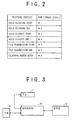
- FIG. 2 shows an allocation table in which defined values are allocated to DTMF command signals which correspond to a plurality of telephone services of the data processing device in the communication support system of the present invention.
- a DTMF (dual-tone multiple frequency) pulse is used by the telephone unit (TU) to transmit a command signal to the communication control device (CCD). More specifically, as shown in FIG. 2, defined values related to a ten-key pad ("0"-"9", "#” and "*") of the telephone unit are allocated to a plurality of DTMF command signals corresponding to the plurality of telephone services of the data processing device (DPD). The defined values may be suitably selected from those that are not ordinarily used to indicate a telephone number of a destination terminal in the telephone network.
- the defined values used by the communication support system of the present invention include, for examples, "*1" through “*4" and “*7” through “*9” as shown in FIG. 2.
- a DTMF command signal sent by the telephone unit (TU) is detected by the communication control device (CCD).
- the DTMF command signal indicates a specific one of the plurality of telephone services.
- the plurality of telephone services provided by the data processing device (DPD) in the communication support system of the present invention include, for example, voice recording start ("*1"), voice recording end ("*2"), voice playback start ("*3"), voice playback end ("*4"), file transmission start ("*7"), file transmission end ("*8”), and telephone number entry (“*9”).
- the communication control device (CCD) it is possible to determine which of the plurality of telephone services is indicated by the DTMF command signal sent by the telephone unit (TU).
- dial pulse is used by the telephone unit 1 to transmit a command signal to the communication control device 2
- other defined values related to the ten-key pad of the telephone unit 1 may be allocated to a plurality of dial-pulse command signals instead of the example of FIG. 2.
- the plurality of dial-pulse command signals respectively correspond to the plurality of telephone services.
- a plurality of specifically-designed keys (“A", "B", ...) of the telephone unit 1 may be allocated to the plurality of DTMF command signals, instead of the ten-key pad of the telephone unit 1.
- the plurality of specifically designed keys respectively correspond to the plurality of telephone services.
- the communication control device 2 may be considered a modem or a terminal adapter that connects both the telephone unit 1 and the data processing device 3 to the telephone network 4.
- FIG. 3 through FIG. 7 show various examples of construction of the elements of the communication support system.
- a modem, a telephone system having a built-in modem, and a personal computer having a built-in telephone and modem are used to construct the communication support system of the present invention.
- FIG. 3 and FIG. 4 have a construction that is essentially the same as the construction of the elements of the communication support system of FIG. 1.
- a modem 41 is substituted for the communication control device 2 in the communication support system of the present invention.
- the telephone unit 1 includes a radio circuit 11 and a cordless telephone 12.
- the cordless telephone 12 provides existing radio signal transmission and reception functions at a remote location of the radio circuit 11.
- the radio circuit 11 provides conversion of a radio signal from the cordless telephone 12 into voice data and conversion of voice data from the telephone line into a radio signal.
- FIG. 5 utilizes a telephone system 42 having a built-in modem.
- the modem 41 contained in the telephone system 42 is substituted for the communication control device 2 in the communication support system of the present invention.
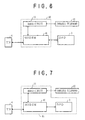
- the example of FIG. 6 utilizes a telephone system 43 having a built-in modem.
- the modem 41 contained in the telephone system 43 is substituted for the communication control device 2 in the communication support system of the present invention.
- the radio circuit 11 in the telephone system 43 forms a part of the communication control device 2, and the cordless telephone 12 is substituted for the telephone unit 1.
- FIG. 7 utilizes a personal computer 44 having a built-in telephone and a built-in modem.
- the modem 41 and the data processing device 3, contained in the personal computer 44 are substituted for the communication control device 2 and the data processing device 3 in the communication support system of the present invention.
- the radio circuit 11 in the personal computer 44 forms a part of the communication control device 2, and the cordless telephone 12 is substituted for the telephone unit 1.
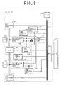
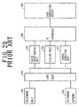
- FIG. 8 shows one embodiment of the communication control device in the communication support system of the present invention.
- one of the telephone services including the voice recording and playback, file transmission and telephone number entry, is provided when the user of the telephone unit transmits a DTMF command signal from the telephone unit to the communication control device to remotely control the data processing device.
- the communication support system generally has a telephone unit (TU) 101, a communication control device (CCD) 200, a data processing device (DPD) 115, and a telephone network (TN) 102.
- the communication support system is adapted to connect the TU 101 through the CCD 200 to the DPD 115, and adapted to connect the TN 102 to the CCD 200.
- a PC interface unit (PC/I) 114 is provided between the CCD 200 and the DPD 115.
- the CCD 200 in the present embodiment comprises a relay 103, a relay control unit 104, a 2-line/4-line converter unit 105, a 2-line/4-line converter unit 106, a DTMF detection unit 107, a data modulator/demodulator unit (DATA MODEM) 108, a DTMF detection unit 109, a signal detection unit 110, a DTMF generator unit 111, a central processing unit (CPU) 112, a bus 113, a direct-current (DC) detection unit 116, a direct-current (DC) detection unit 117, and a switch (SW) 118.
- the execution of one of the telephone services is requested of the DPD 115 by the CCD 200 based on a corresponding one of the plurality of DTMF command signals sent from the telephone unit 101.
- the TU 101 provides the existing voice signal transmission and receiving functions and the existing dialing function.
- the TU 101 transmits a DTMF command signal to the CCD 200 to remotely control the DPD 115.
- the TN 102 is, for example, a public switched telephone network.
- the user of the TU 101 may communicate with a person of a destination terminal over the TN 102 by voice.
- the CPU 112 receives signals from the elements of the CCD 200 connected through the bus 113, performs control processing based on the received signals, and controls the elements of the CCD 200.
- the DC detection unit 117 provides detection of an on-hook condition of the TU 101.
- the DC detection unit 116 provides detection of a disconnection of the TN 102 from the CCD 200.
- a telephone service processing related to the flowcharts of FIGs. 9-19 is program code instructions stored in a memory (not shown) of the CCD 200.
- the memory of the CCD 200 is, for example, a ROM (read-only memory).
- the memory corresponds to a processor readable medium in the claims.
- the processor readable medium may be any one of instruction storage devices, such as, for example, magnetic disks including floppy disks, optical disks including CD-ROMs, magneto-optical disks including MOs, semiconductor memory cards, such as PC cards and miniature cards, and other types of computer usable devices and media.
- the memory of the CCD 200 may store encoded or non-encoded instructions.
- the instructions may be installed from a floppy disk (or a CD-ROM) to a hard disk drive (not shown) of the CCD 200 first, transferred to a RAM (not shown) of the CCD 200 and then read by the CPU 112.
- the memory of the CCD 200 may store either all or a part of the instructions related to the flowcharts of FIGs. 9-19.
- the relay control unit 104 controls the relay 103 under the control of the CPU 112.
- the relay 103 switches on or off a connection line between the TU 101 and the TN 102 when the relay 103 is controlled by the relay control unit 104.
- the relay 103 when power is supplied to place the CCD 200 in an initial condition, the relay 103 is set in an off-state by the relay control unit 104 so that the TU 101 is disconnected from the TN 102.
- the relay 103 is set in an on-state by the relay control unit 104 so that the TU 101 is connected to the TN 102 through the relay 103.
- the 2-line/4-line converter unit 105 separates a data signal sent from the TN 102 into a DTMF signal and a voice signal. Similarly, the 2-line/4-line converter unit 106 separates a data signal sent by the TU 101 into a DTMF signal and a voice signal. Also, the 2-line/4-line converter unit 106 supplies power to the CCD 200.
- the DTMF detection unit 107 provides detection of a DTMF signal sent by the TN 102.
- the DTMF detection unit 109 provides detection of a DTMF signal (including the DTMF command signal) sent by the TU 101.
- the DATA MODEM 108 provides modulation and demodulation of the voice signal on the line from the TN 102 or the line from the TU 101.
- the signal detection unit 110 provides detection of various signals sent from or to the telephone line (the TU 101 and the TN 102), the signals including a busy-tone signal, a ring-tone signal, a ring-back-tone signal, an on-hook signal, and an off-hook signal.
- the busy-tone signal when detected by the signal detection unit 110, indicates that a telephone call between the TU 101 and the TN 102 is in progress.
- the ring-tone signal when detected by the signal detection unit 110, indicates that a call from a telephone in the TN 102 is being received by the TU 101.
- the ring-back-tone signal when detected by the signal detection unit 110, indicates that a telephone call from the TU 101 is being received by a telephone in the TN 102.
- the DTMF generator unit 111 generates a DTMF signal (indicating a telephone number) under control of the CPU 112, and transmits the DTMF signal from the CCD 200 to the TN 102.
- the PC interface unit 114 provides a personal-computer interface to connect the CCD 200 and the DPD 115.
- the DPD 115 provides execution of the telephone service processing in order to provide the telephone service for the user of the TU 101.
- the switch 118 switches on or off a connection line of the converter unit 105 and the converter unit 106 under control of the CPU 112, and switches on or off a connection line of the converter unit 105 and the DTMF generator unit 111 under control of the CPU 112.
- the switch 118 switches on the connection line of the converter unit 105 and the converter unit 106 in order to connect the TU 101 and the TN 102, and switches off the connection line of the converter unit 105 and the DTMF generator unit 111.
- the switch 118 switches off the connection line of the converter unit 105 and the converter unit 106 in order to disconnect the TN 102 from the TU 101.
- the switch 118 switches on the connection line of the converter unit 105 and the DTMF generator unit 111 in order to connect the DTMF generator unit 111 and the TN 102.
- the switch 118 is controlled by the CPU 112 so that the switch 118 switches off the connection line of the converter unit 105 and the converter unit 106 to disconnect the TN 102 from the TU 101.
- the relay 103 is set in the off-state by the relay control unit 104.
- the user of the TU 101 transmits a DTMF command signal from the TU 101 to the CCD 200 to remotely control the DPD 115 and obtain a desired telephone service of the DPD 115.
- the DTMF detection unit 109 detects the DTMF command signal sent by the TU 101.
- the CPU 112 is notified that the DTMF command signal from the TU 101 is detected by the DTMF detection unit 109. Then, the CPU 112 notifies the DPD 115 that an event has occurred in the CCD 200 due to the DTMF command signal sent by the TU 101.
- a telephone service application program provided in the DPD 115 is performed by the DPD 115 based on the content of the DTMF command signal, so that the desired telephone service of the DPD 115 is provided for the user of the TU 101.
- the switch 118 when the switch 118 is set in the off-state of the connection line of the converter unit 105 and the converter unit 106, the user of the TU 101 transmits a DTMF signal (which indicates a telephone number of a destination terminal and is different from the DTMF command signal) through the CCD 200 to the TN 102 in order to transmit a telephone call to a destination terminal in the TN 102.
- the switch 118 is controlled by the CPU 112 so that the switch 118 switches on the connection line of the converter unit 105 and the DTMF generator unit 111 to connect the DTMF generator unit 111 and the TN 102.
- the DTMF generator unit 111 generates a DTMF signal based on the content of the DTMF signal sent by the TU 101, and transmits the generated DTMF signal from the CCD 200 to the TN 102. After the DTMF signal (indicating the telephone number) is transmitted to the TN 102, the DTMF generator unit 111 notifies the CPU 112 that the transmission of the DTMF signal has ended. Then the switch 118 is controlled by the CPU 112 so that the switch 118 switches off the connection line of the converter unit 105 and the DTMF generator unit 111. Therefore, the CPU 112 inhibits transmission of a DTMF signal from the TU 101 to the TN 102.
- the DTMF detection unit 109 provides not only detection of a DTMF command signal (indicating one of the defined values) sent by the TU 101 but also detection of a different DTMF signal (indicating a telephone number) sent by the TU 101.
- a ring-back-tone signal from the TN 102 is sent to the CCD 200.
- the ring-back-tone signal is detected by the signal detection unit 110.
- the signal detection unit 110 notifies the CPO 112 that the ring-back-tone signal from the TN 102 is detected.
- the switch 118 is controlled by the CPU 112 so that the switch 118 switches on the connection line of the converter unit 105 and the converter unit 106 to connect the TN 102 and the TU 101.
- the user of the TU 101 transmits a DTMF command signal from the TU 101 to the CCD 200, and the DTMF command signal from the TU 101 is detected by the DTMF detection unit 109.
- the DTMF detection unit 109 notifies the CPU 112 that the DTMF command signal sent by the TU 101 is detected.
- the switch 118 is controlled by the CPU 112 so that the switch 118 switches off the connection line of the converter unit 105 and the converter unit 106 to disconnect the TN 102 from the TU 101. Therefore, the CPU 112 inhibits transmission of a DTMF signal from the TU 101 to the TN 102 through the switch 118.
- the CPU 112 notifies the DPD 115 that an event has occurred in the CCD 200 due to the DTMF command signal sent by the TU 101.
- a telephone service processing program in the DPD 115 is executed by the DPD 115 based on the content of the DTMF command signal, so that the desired telephone service of the DPD 115 is provided for the user of the TU 101. Therefore, it is possible to provide the telephone service of the DPD 115 for the telephone user even when the telephone call between the TU 101 and the TN 102 is in progress and the telephone user transmits a DTMF command signal from the TU 101 to remotely control the DPD 115.
- a person of the destination terminal in the TN 102 may transmit a DTMF command signal (or a different DTMF signal) to the CCD 200.
- the DTMF signal from the TN 102 is detected by the DTMF detection unit 107.
- the DTMF detection unit 107 notifies the CPU 112 that the DTMF signal sent from the TN 102 is detected.
- the CPU 112 notifies the DPD 115 that an event has occurred in the CCD 200 due to the DTMF signal sent from the TN 102.
- the DPD 115 executes an invalid-access prevention processing program (different from the telephone service processing program) in the DPD 115 based on the content of the DTMF signal sent from the TN 102, so that a warning message from the DPD 115 is provided for the person of the destination terminal in the TN 102.
- an invalid-access prevention processing program different from the telephone service processing program
- FIG. 9 shows a main routine of a telephone service processing program executed by the CPU 112 of the CCD 200 of FIG. 8 to remotely control the DPD 115 and obtain a desired telephone service of the DPD 115.
- FIG. 10 shows a PC interface initialization in the main routine of FIG. 9.
- FIG. 11 shows a CCD initialization in the main routine of FIG. 9.
- the program code instructions cause the CPU 112 to initialize all internal flags of the CCD 200 (S11).
- the program code instructions cause the CPU 112 to set the relay 103 in the on-state by controlling the relay control unit 104 (S12).
- the relay 103 switches on the connection line of the TU 101 and the TN 102 so that the TU 101 is connected through the CCD 200 to the TN 102.
- the CCD initialization of FIG. 11 is finished.
- the program code instructions cause the CPU 112 to set a status portion of the memory of the CCD 200 at a predetermined value (S21). After the setting of the status portion of the above S21 is performed, the program code instructions cause the CPU 112 to set a data portion of the memory of the CCD 200 at "00" (S22). After the setting of the data portion of the above S22 is performed, the program code instructions cause the CPU 112 to set a data strobe signal in an on-state (S23). After a given time period, the program code instructions cause the CPU 112 to set the data strobe signal in an off-state (S23). In this case, setting the status portion at the predetermined value indicates that data is currently included in the data portion of the memory. After the setting of the data strobe signal of the above S23 is performed, the PC interface initialization of FIG. 10 is finished.
- the relay 103 when power is supplied to place the CCD 200 in the initial condition, the relay 103 is set in the off-state by the relay control unit 104 so that the TN 102 is disconnected from the TU 101.
- the CPU 112 of the CCD 200 executes an interrupt processing routine in response to an interrupt signal, and the execution of the interrupt processing routine occurs simultaneously with the execution of the main routine of FIG. 9.
- the interrupt signal is supplied to the CPU 112 by either the DPD 115 or the CCD 200, which causes the interrupt processing routine to be executed.
- the DTMF detection unit 107, the DTMF detection unit 109, or the signal detection unit 110 supplies a detection signal to the CPU 112 as the interrupt signal which causes the execution of the interrupt processing routine.
- the DPD 115 supplies a control command to the CPU 112 as the interrupt signal which causes the execution of the interrupt processing routine, and this control command includes a defined value comparison mode setting command, a defined value comparison mode resetting command, a DTMF command transmission setting command, a secret number setting command, and a line switching command.
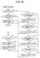
- FIG. 18 shows the interrupt processing routine executed by the CPU 112 of the CCD 200.
- the program code instructions cause the CPU 112 to determine whether the interrupt has occurred due to a control command sent by the DPD 115 (S161).
- the program code instructions cause the CPU 112 to determine whether the control command sent by the DPD 115 is a defined value comparison mode setting command (S164). When the result of the above S164 is affirmative, the program code instructions cause the CPU 112 to set the CCD 200 in a defined value comparison mode (S165). After the setting of the CCD 200 of the above S165 is performed, the interrupt processing routine of FIG. 18 is finished.
- the program code instructions cause the CPU 200 to determine whether the control command is a defined value comparison mode resetting command (S166). When the result of the above S166 is affirmative, the program code instructions cause the CPU 112 to set the CCD 200 in a non-comparison mode (S167). After the setting of the CCD 200 of the above S167 is performed, the interrupt processing routine of FIG. 18 is finished.
- the program code instructions cause the CPU 112 to determine whether the control command sent by the DPD 115 is a DTMF command transmission setting command (S168). When the result of the above S168 is affirmative, the program code instructions cause the CPU 112 to store the content of the DTMF command signal in the memory of the CCD 200 (S169). When the DTMF command transmission setting command is received, the CCD 200 transmits the content of the DTMF command signal, stored in the memory of the CCD 200, to the DPD 115. After the storing of the DTMF command signal of the above S169 is performed, the interrupt processing routine of FIG. 18 is finished.
- the program code instructions cause the CPU 200 to determine whether the control command is a secret number setting command (S170). When the result of the above S170 is affirmative, the program code instructions cause the CPU 112 to store the content of the control command in the memory of the CCD 200 as the secret number (S171). After the storing of the secret number of the above S171 is performed, the interrupt processing routine of FIG. 18 is finished.
- the program code instructions cause the CPU 200 to determine whether the control command is a line switching command (S172).
- the program code instructions cause the CPU 112 to control the switch 118 so that the switch 118 switches on the connection line of the converter unit 105 and the converter unit 106 to connect the TN 102 and the TU 101 (S173).
- the program code instructions cause the CPU 112 to set a coincidence processing end signal (S174). After the setting of the coincidence processing end signal of the above S174 is performed, the interrupt processing routine of FIG. 18 is finished.
- the program code instructions cause the CPU 112 to determine whether the interrupt has occurred due to a detection signal sent by one of the DTMF detection unit 107, the DTMF detection unit 109, and the signal detection unit 110 (S162).
- the interrupt processing routine of FIG. 18 is finished.
- the program code instructions cause the CPU 112 to store the content of the detection signal (or one of the DTMF command signal, the busy-tone signal, the ring-tone signal, ring-back-tone signal, the on-hook signal and the off-hook signal) in the memory of the CCD 200 (S163). After the storing of the detection signal of the above S163 is performed, the interrupt processing routine of FIG. 18 is finished.
- the DPD 115 provides execution of the telephone service processing in order to provide the telephone service for the user of the TU 101 based on a previous stored condition and the DTMF command signal sent by the TU 101.
- the telephone service is, for example, one of the voice recording, the voice playback, the file transmission, and the telephone number entry.
- the CPU 112 of the CCD 200 performs the CCD control processing routine S3 in the main routine of FIG. 9.
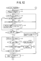
- FIG. 12 and FIG. 13 show the CCD control processing routine S3 in the main routine of FIG. 9.
- the program code instructions cause the CPU 112 to perform the CCD control processing routine of FIGs. 12 and 13 when a detection signal from one of the units 107, 109 and 110 is detected during the interrupt processing routine of FIG. 18.
- the program code instructions cause the CPU 112 to control the switch 118 so that the switch 118 switches off the connection line of the converter unit 105 and the converter unit 106 to disconnect the TN 102 from the TU 101 (S101).
- the program code instructions cause the CPU 112 to perform a detection signal reading (S102).
- FIG. 19 shows the detection signal reading in the CCD control processing routine of FIGs. 12 and 13.
- the program code instructions cause the CPU 112 to read out the detection signal (which has been stored in the above S163 in the interrupt processing of FIG. 18) from the memory of the CCD 200 (S69). After the reading of the detection signal of the above S69 is performed, the program code instructions cause the CPU 112 to determine whether the detection signal can be actually read out from the memory of the CCD 200 (S70). When the result of the above S70 is negative, the detection signal reading of FIG. 19 is finished.
- the program code instructions cause the CPU 112 to initialise a corresponding portion of the memory of the CCD 200 in which the detection signal was stored during the interrupt processing of FIG. 18 (S71). After the initialization of the above S71 is performed, the program code instructions cause the CPU 112 to return a code indicating the content of the detection signal read out in the above S69 (S72). After the returning of the code of the above S72 is performed, the detection signal reading of FIG. 19 is finished.
- the program code instructions cause the CPU 112 to determine whether the off-hook signal is indicated by the return code obtained by the detection signal reading S102 (S103).
- the program code instructions cause the CPU 112 to determine whether the ring-tone signal is indicated by the return code obtained by the detection signal reading S102 (S104).
- the program code instructions cause the CPU 112 to return to the detection signal reading of the above S102.
- the CPU 112 waits for a next detection signal to be detected within the CCD 200 and read out from the memory of the CCD 200 during the detection signal reading of the above S102.
- the program code instructions cause the CPU 112 to set a corresponding portion of the memory of the CCD 200 at a predetermined value, the predetermined value indicating that the ring-tone signal was previously stored in the memory of the CCD 200 (S105).
- the program code instructions cause the CPU 112 to return to the detection signal reading of the above S102.
- the CPU 112 waits for a next detection signal to be detected within the CCD 200 and read out from the memory of the CCD 200 during the detection signal reading of the above S102.
- the program code instructions cause the CPU 112 to determine whether the predetermined value (indicating that the ring-tone signal was previously stored in the memory of the CCD 200) is already set in the corresponding portion of the memory of the CCD 200 (S106).
- the program code instructions cause the CPU 112 to perform the detection signal reading of FIG. 19 (S107).
- the CPU 112 waits for a next detection signal to be detected within the CCD 200 and read out from the memory of the CCD 200 during the detection signal reading of the above S107.
- the program code instructions cause the CPU 112 to delete the predetermined value (which has been stored in the above S105) in the corresponding portion of the memory of the CCD 200 (S112).
- the program code instructions cause the CPU 112 to control the switch 118 so that the switch 118 switches on the connection line of the converter unit 105 and the converter unit 106 to connect the TU 101 and the TN 102 (S111).
- the program code instructions cause the CPU 112 to perform the detection signal reading of FIG. 19 (S121) as shown in FIGs. 12 and 13.
- the CPU 112 waits for a next detection signal to be detected within the CCD 200 and read out from the memory of the CCD 200 during the detection signal reading of the above S121.
- the program code instructions cause the CPU 112 to determine whether the DTMF signal (which is locally sent by the TU 101 and detected by the DTMF detection unit 109) is indicated by the return code obtained by the detection signal reading S107 (S108).
- the program code instructions cause the CPU 112 to perform a DTMF processing (S113).
- S113 a DTMF processing
- the DTMF processing will be described later with reference to FIG. 15.
- the program code instructions cause the CPU 112 to return to the detection signal reading of the above S107.
- the CPU 112 waits for a next detection signal to be detected within the CCD 200 and read out from the memory of the CCD 200 during the detection signal reading of the above S107.
- the program code instructions cause the CPU 112 to determine whether the on-hook signal is indicated by the return code obtained by the detection signal reading S107 (S109). When the result of the above S109 is affirmative, the program code instructions cause the CPU 112 to perform an on-hook processing (S114). The on-hook processing will be described later with reference to FIG. 14. After the on-hook processing of the above S114 is performed, the program code instructions cause the CPU 112 to return to the above S101.
- the program code instructions cause the CPU 112 to determine whether the ring-back-tone signal is indicated by the return code obtained by the detection signal reading S107 (S110).
- the program code instructions cause the CPU 112 to return to the detection signal reading of the above S107.
- the CPU 112 waits for a next detection signal to be detected within the CCD 200 and read out from the memory of the CCD 200 during the detection signal reading of the above S107.
- the program code instructions cause the CPU 112 to perform the above S111 in which the switch 118 is controlled by the CPU 112 so that the switch 118 switches on the connection line of the converter unit 105 and the converter unit 106 to connect the TU 101 and the TN 102.
- the program code instructions cause the CPU 112 to perform the detection signal reading of the above S121.
- the CPU 112 waits for a next detection signal to be detected within the CCD 200 and read opt from the memory of the CCD 200 during the detection signal reading of the above S121.
- the program code instructions cause the CPU 112 to determine whether the on-hook signal is indicated by the return code obtained by the detection signal reading S121 (S122). When the result of the above S122 is affirmative, the program code instructions cause the CPU 112 to perform the on-hook processing (S133). The on-hook processing will be described later with reference to FIG. 14. After the on-hook processing of the above S133 is performed, the program code instructions cause the CPU 112 to return to the above S101.
- the program code instructions cause the CPU 112 to determine whether the DTMF signal (which is remotely sent from the TN 102 and detected by the DTMF detection unit 107) is indicated by the return code obtained by the detection signal reading S121 (S123).
- the program code instructions cause the CPU 112 to perform a DTMF notification (S124).
- the DTMF notification processing will be described later with reference to FIG. 15.
- the program code instructions cause the CPU 112 to return to the detection signal reading of the above S121.
- the CPU 112 waits for a next detection signal to be detected within the CCD 200 and read out from the memory of the CCD 200 during the detection signal reading of the above S121.
- the program code instructions cause the CPU 112 to determine whether the DTMF signal (which is locally sent by the TU 101 and detected by the DTMF detection unit 109) is indicated by the return code obtained by the detection signal reading S121 (S125).
- the program code instructions cause the CPU 112 to return to the detection signal reading of the above S121.
- the CPU 112 waits for a next detection signal to be detected within the CCD 200 and read out from the memory of the CCD 200 during the detection signal reading of the above S121.
- the program code instructions cause the CPU 112 to determine whether the CCD 200 is set in the defined value comparison mode (S126). When the result of the above S126 is negative, the program code instructions cause the CPU 112 to return to the detection signal reading of the above S121. The CPU 112 waits for a next detection signal to be detected within the CCD 200 and read out from the memory of the CCD 200 during the detection signal reading of the above S121.
- the program code instructions cause the CPU 112 to perform a defined value comparison processing (S127).
- S127 a defined value comparison processing
- the defined value comparison processing will be described later with reference to FIG. 16.
- the program code instructions cause the CPU 112 to determine whether the defined value comparison processing has normally ended (S128).
- the program code instructions cause the CPU 112 to perform the detection signal reading of FIG. 19 (S129).
- the CPU 112 waits for a next detection signal to be detected within the CCD 200 and read out from the memory of the CCD 200 during the detection signal reading of the above S129.
- the program code instructions cause the CPU 112 to determine whether the DTMF signal (which is locally sent by the TU 101 and detected by the DTMF detection unit 109) is indicated by the return code obtained by the detection signal reading S129 (S130).
- the program code instructions cause the CPU 112 to determine whether the on-hook signal is indicated by the return code obtained by the detection signal reading S129 (S131).
- the program code instructions cause the CPU 112 to perform the on-hook processing (S132). The on-hook processing will be described later with reference to FIG. 14. After the on-hook processing of the above S132 is performed, the program code instructions cause the CPU 112 to return to the above S101.
- the program code instructions cause the CPU 112 to determine whether coincidence is indicated by a return code obtained by the defined value comparison processing S127 (S134).
- the program code instructions cause the CPU 112 to perform a coincidence processing (S135).
- the coincidence processing will be described later with reference to FIG. 17.
- the program code instructions cause the CPU 112 to determine whether the off-hook signal is indicated by the return code obtained during the coincidence processing S135 (S136). When the result of the above S136 is affirmative, the program code instructions cause the CPU 112 to return to the above S101. When the result of the above S136 is negative, the program code instructions cause the CPU 112 to return to the above S121.
- the CPU 112 waits for a next detection signal to be detected within the CCD 200 and read out from the memory of the CCD 200 during the detection signal reading of the above S121.
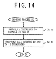
- FIG. 14 shows the on-hook processing in the CCD control processing routine of FIGs. 12 and 13.
- the on-hook processing of FIG. 14 is performed by the CPU 112 of the CCD 200.
- the program code instructions cause the CPU 112 to control the switch 118 so that the switch 118 switches on the connection line of the converter unit 105 and the converter unit 106 to connect the TU 101 and the TN 102 (S141).
- the program code instructions cause the CPU 112 to terminate the telephone call between the TU 101 and the TN 102. That is, the telephone call between the TU 101 and the TN 102 is finished.
- the program code instructions cause the CPU 112 to return back to the CCD control processing routine of FIGs. 12 and 13.
- FIG. 15 shows the DTMF processing and the DTMF notification in the CCD control processing routine of FIGs. 12 and 13.
- the CPU 112 when the CPU 112 is notified during the CCD control processing of FIGs. 12 and 13 that the DTMF signal from the TU 101 is detected by the DTMF detection unit 109, the DTMF processing is performed by the CPU 112.
- the program code instructions cause the CPU 112 to determine whether the content of the DTMF signal from the TU 101 is included in the allocation table of FIG. 2 (S151). When the result of the above S151 is negative, the program code instructions cause the CPU 112 to control the switch 118 so that the switch 118 switches on the connection line of the converter unit 105 and the DTMF generator unit 111 to connect the DTMF generator unit 111 to the TN 102 (S152).
- the program code instructions cause the CPU 112 to control the DTMF generator unit 111 so that the DTMF generator unit 111 generates a DTMF signal based on the content of the DTMF signal sent by the TU 101, and transmits the DTMF signal to the TN 102 (S153).
- the program code instructions cause the CPU 112 to control the switch 118 so that the switch 118 switches off the connection line of the converter unit 105 and the DTMF generator unit 111 to disconnect the DTMF generator unit 111 from the TN 102 (S154).
- the DTMF processing of FIG. 15 is finished.
- the CPU 112 inhibits transmission of a DTMF signal from the TU 101 to the TN 102 when the content of the DTMF signal from the TU 101 is not included in the allocation table containing the defines values of the DTMF command signals for the plurality of telephone services of the DPD 115.
- the program code instructions cause the CPU 112 to set the status portion of the memory of the CCD 200 at the predetermined value (S155). After the setting of the status portion of the above S155 is performed, the program code instructions cause the CPU 112 to set the data portion of the memory at a value indicated by the DTMF signal from the TU 101 (or from the TN 102) (S156). After the setting of the data portion of the above S156 is performed, the program code instructions cause the CPU 112 to set the data strobe signal in the on-state (S157). The DPD 115 is notified by the CCD 200 that the event has occurred due to the DTMF command signal sent by the TU 101. After a given time period, the program code instructions cause the CPU 112 to set the data strobe signal in the off-state (S157). After the setting of the data strobe signal of the above S157 is performed, the DTMF processing of FIG. 15 is finished.
- the DTMF notification is performed by the CPU 112.
- the program code instructions cause the CPU 112 to perform the above-mentioned steps S155-S157 as shown in FIG. 15.
- the DPD 115 is notified by the CCD 200 that the event has occurred due to the DTMF signal sent from the TN 102.
- FIG. 16 shows the defined value comparison processing in the CCD control processing routine of FIGs. 12 and 13.
- the CPU 112 is notified that the DTMF signal from the TU 101 is detected by the DTMF detection unit 109, and that the CCD 200 is set in the defined value comparison mode, and then the defined value comparison processing is performed by the CPU 112.
- the program code instructions cause the CPU 112 to get the character (or the defined value) from the defined value comparison mode setting command (S181). After the above S181 is performed, the program code instructions cause the CPU 112 to determine whether the content of the DTMF signal from the TU 101 accords with the character of the defined value comparison mode setting command (S182).
- the program code instructions cause the CPU 112 to determine whether the defined value comparison has normally ended (S183).
- the program code instructions cause the CPU 112 to increment the comparison pointer and returns a code indicating that the defined value comparison yields coincidence and normal end (S184). After the above S184 is performed, the defined value comparison processing of FIG. 16 is finished.
- the program code instructions cause the CPU 112 to initialise the comparison pointer and returns a code indicating that the defined value comparison yields non-coincidence (S185). After the above S185 is performed, the defined value comparison processing of FIG. 16 is finished.
- the program code instructions cause the CPU 112 to initialize the comparison pointer and returns a code indicating that the defined value comparison yields coincidence and abnormal end (S186). After the above S186 is performed, the defined value comparison processing of FIG. 16 is finished.
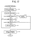
- FIG. 17 shows the coincidence processing in the CCD control processing routine of FIGs. 12 and 13.
- the CPU 112 is notified that the return code obtained by the defined value comparison processing indicates coincidence, and then the coincidence processing is performed by the CPU 112.
- the program code instructions cause the CPU 112 to control the switch 118 so that the switch 118 switches off the connection line of the converter unit 105 and the converter unit 106 to disconnect the TN 102 from the TU 101 (S191).
- the program code instructions cause the CPU 112 to perform the detection signal reading of FIG. 19 (S192).
- the program code instructions cause the CPU 112 to determine whether the on-hook signal is indicated by the return code obtained by the detection signal reading (S193).
- the program code instructions cause the CPU 112 to perform the on-hook processing of FIG. 14 (S197). After the on-hook processing of the above S197 is performed, the program code instructions cause the CPU 112 to control the switch 118 so that the switch 118 switches on the connection line of the converter unit 105 and the converter unit 106 to connect the TU 101 and the TN 102 (S198). After the above S198 is performed, the coincidence processing of FIG. 17 is finished.
- the program code instructions cause the CPU 112 to determine whether the DTMF signal is indicated by the return code obtained by the detection signal reading (S194).
- the program code instructions cause the CPU 112 to determine whether the end signal is detected (S195).
- the program code instructions cause the CPU 112 to perform the above S198. After the above S198 is performed, the coincidence processing of FIG. 17 is finished.
- the program code instructions cause the CPU 112 to perform the DTMF notification of FIG. 15 (S196). After the above S196 is performed, the program code instructions cause the CPU 112 to return to the detection signal reading of the above S192.
Landscapes
- Engineering & Computer Science (AREA)
- Signal Processing (AREA)
- Automation & Control Theory (AREA)
- Telephonic Communication Services (AREA)
- Telephone Function (AREA)
Applications Claiming Priority (3)
| Application Number | Priority Date | Filing Date | Title |
|---|---|---|---|
| JP255797/97 | 1997-09-19 | ||
| JP9255797A JPH1198270A (ja) | 1997-09-19 | 1997-09-19 | 通信支援装置 |
| JP25579797 | 1997-09-19 |
Publications (3)
| Publication Number | Publication Date |
|---|---|
| EP0903907A2 true EP0903907A2 (de) | 1999-03-24 |
| EP0903907A3 EP0903907A3 (de) | 2004-12-29 |
| EP0903907B1 EP0903907B1 (de) | 2008-07-30 |
Family
ID=17283775
Family Applications (1)
| Application Number | Title | Priority Date | Filing Date |
|---|---|---|---|
| EP98302303A Expired - Lifetime EP0903907B1 (de) | 1997-09-19 | 1998-03-26 | Telefonendgerät mit Datenverarbeitungseinrichtung und System zur Unterstützung einer Kommunikation |
Country Status (5)
| Country | Link |
|---|---|
| US (1) | US7406162B2 (de) |
| EP (1) | EP0903907B1 (de) |
| JP (1) | JPH1198270A (de) |
| CN (1) | CN1140988C (de) |
| DE (1) | DE69839791D1 (de) |
Families Citing this family (5)
| Publication number | Priority date | Publication date | Assignee | Title |
|---|---|---|---|---|
| JP3938132B2 (ja) * | 2003-10-10 | 2007-06-27 | 株式会社日立製作所 | 移動通信端末及びコンテンツ配信システム |
| US7665146B2 (en) * | 2005-07-14 | 2010-02-16 | Research In Motion Limited | Password methods and systems for use on a mobile device |
| US10888232B2 (en) * | 2011-08-20 | 2021-01-12 | Philips Image Guided Therapy Corporation | Devices, systems, and methods for assessing a vessel |
| JP6146827B2 (ja) | 2015-09-10 | 2017-06-14 | Necプラットフォームズ株式会社 | 電話交換装置および方法並びにプログラム |
| JP6275210B2 (ja) * | 2016-07-28 | 2018-02-07 | 株式会社Nttドコモ | 呼制御装置及び通信システム |
Family Cites Families (30)
| Publication number | Priority date | Publication date | Assignee | Title |
|---|---|---|---|---|
| US3569634A (en) * | 1967-06-27 | 1971-03-09 | Claudio Amadasi | Blocking circuit for telephone apparatus |
| US3553382A (en) * | 1967-08-04 | 1971-01-05 | Edward R Edelberg | Toll call signalling and diverting system |
| US3757055A (en) * | 1972-03-21 | 1973-09-04 | Cann G Mc | Electronic toll restrictor |
| US4006316A (en) * | 1974-08-12 | 1977-02-01 | International Mobile Machines Corporation | Code-controlled detection and function actuating system |
| GB1569257A (en) * | 1975-11-17 | 1980-06-11 | Murray L Q | Of a telephone instrument telephone security device for preventing unauthorised use |
| US4124781A (en) * | 1977-08-31 | 1978-11-07 | Akzona Incorporated | Telephone toll restrictor |
| US4171469A (en) * | 1978-04-27 | 1979-10-16 | Brooks Fred E | Abbreviated dialing system |
| JPS5768965A (en) | 1980-10-17 | 1982-04-27 | Fujitsu Ltd | Telephone line information service system |
| JPS5826569B2 (ja) | 1980-12-29 | 1983-06-03 | 富士通株式会社 | 自動電源投入・切断装置 |
| US4425480A (en) * | 1981-11-20 | 1984-01-10 | Communication Equipment And Engineering Co. | Telephone station apparatus with selective restricting of local calls |
| JPH0644788B2 (ja) * | 1984-10-26 | 1994-06-08 | 橋本コ−ポレイション株式会社 | 留守番電話による附加装置のコントロ−ル装置 |
| US4885766A (en) * | 1986-01-31 | 1989-12-05 | Sharp Kabushiki Kaisha | Remote control device using a telephone line |
| JP2680575B2 (ja) | 1987-04-01 | 1997-11-19 | キヤノン株式会社 | 通信装置 |
| US4918722A (en) * | 1988-05-11 | 1990-04-17 | Brooktrout Technology, Inc. | Control of electronic information delivery |
| US5220595A (en) * | 1989-05-17 | 1993-06-15 | Kabushiki Kaisha Toshiba | Voice-controlled apparatus using telephone and voice-control method |
| JPH0461543A (ja) | 1990-06-29 | 1992-02-27 | Sharp Corp | テレビ電話装置 |
| US5276727A (en) * | 1991-06-24 | 1994-01-04 | Samsung Electronics, Co. Ltd. | Remote maintenance method and device thereof in private branch exchange system |
| JPH0556190A (ja) | 1991-08-28 | 1993-03-05 | Matsushita Electric Ind Co Ltd | テレビシステム |
| JPH0575823A (ja) | 1991-09-17 | 1993-03-26 | Matsushita Electric Ind Co Ltd | フアクシミリ装置 |
| JP3049928B2 (ja) | 1992-03-17 | 2000-06-05 | 松下電器産業株式会社 | コードレス電話による電子機器の遠隔制御システム |
| GB2272600A (en) | 1992-11-12 | 1994-05-18 | Alastair Gordon Fraser | Programming a recording apparatus over a telecommunication system |
| US5710808A (en) * | 1993-02-25 | 1998-01-20 | Eaton; Mark William | Telephone dialling code processor |
| JPH0830352A (ja) | 1994-07-12 | 1996-02-02 | Sony Corp | 情報処理装置 |
| JPH08237299A (ja) | 1995-02-28 | 1996-09-13 | Nec Corp | オムニメディア通信サービスシステム |
| KR100193824B1 (ko) * | 1995-07-06 | 1999-06-15 | 윤종용 | 교환기의 착신 서비스 방법 |
| DE69625793T2 (de) * | 1995-09-29 | 2003-10-02 | At & T Corp., New York | Telefonnetz-dienst zur umwandlung von sprache in wahltöne |
| US5898756A (en) * | 1995-10-13 | 1999-04-27 | Zoom Telephonics, Inc. | Parallel-connected dialing signal transmission-inhibiting device for data transfer over a telephone link |
| JPH09116940A (ja) | 1995-10-19 | 1997-05-02 | Matsushita Electric Ind Co Ltd | コンピュータ・電話統合システム |
| US5864607A (en) * | 1996-08-23 | 1999-01-26 | Compaq Computer Corp. | Communication with a computer using telephones |
| US6041116A (en) * | 1997-05-05 | 2000-03-21 | Aspect Telecommunications Corporation | Method and apparatus for controlling outbound calls |
-
1997
- 1997-09-19 JP JP9255797A patent/JPH1198270A/ja active Pending
-
1998
- 1998-03-24 US US09/046,677 patent/US7406162B2/en not_active Expired - Fee Related
- 1998-03-26 EP EP98302303A patent/EP0903907B1/de not_active Expired - Lifetime
- 1998-03-26 DE DE69839791T patent/DE69839791D1/de not_active Expired - Fee Related
- 1998-04-20 CN CNB981066860A patent/CN1140988C/zh not_active Expired - Fee Related
Also Published As
| Publication number | Publication date |
|---|---|
| CN1140988C (zh) | 2004-03-03 |
| EP0903907A3 (de) | 2004-12-29 |
| EP0903907B1 (de) | 2008-07-30 |
| JPH1198270A (ja) | 1999-04-09 |
| US7406162B2 (en) | 2008-07-29 |
| DE69839791D1 (de) | 2008-09-11 |
| CN1212553A (zh) | 1999-03-31 |
| US20030016802A1 (en) | 2003-01-23 |
| US20030103610A2 (en) | 2003-06-05 |
Similar Documents
| Publication | Publication Date | Title |
|---|---|---|
| US5287401A (en) | Apparatus and method for a modem for detecting a call waiting signal | |
| US5561705A (en) | Apparatus for auto dialing telephone numbers and DTMF tones in a personal communication device | |
| US5208850A (en) | Multi-media information service center and multi-media communication system | |
| US4995073A (en) | Communication apparatus and communication system having automatic attribution switching | |
| US5517557A (en) | Facsimile apparatus with automatic telephone answering function | |
| EP0383834A1 (de) | Stimme/datenschalter | |
| EP0903907A2 (de) | Telefonendgerät mit Datenverarbeitungseinrichtung und System zur Unterstützung einer Kommunikation | |
| US6044133A (en) | Communication support system for providing telephone services of a data processing device by a voice command sent by a telephone unit | |
| JP3022929B2 (ja) | オーディオ及びファクシミリメッセージ格納検索システムの対する信頼性あるアクセスの方法及び装置 | |
| EP0903912B1 (de) | System zur Unterstützung einer Kommunikation | |
| US6345088B1 (en) | Apparatus and methods for handling call waiting in a modem | |
| EP0903917B1 (de) | Kommunikationsunterstützungssystem für Fernsprechferngesteuerte Datenverarbeitungseinrichtung | |
| CN100357928C (zh) | 计算机及使用该计算机的遥控系统 | |
| US6434225B1 (en) | Communication support system in which a ringing sound control processing is performed in response to a call from a telephone network | |
| EP0489917B1 (de) | Kombinierter telefonapparat | |
| EP0382212B1 (de) | Medienverbund-Nachrichtendienstleistungszentrum | |
| US5953397A (en) | Computer system with mode switching function and method of controlling the same | |
| US5140629A (en) | Call transfer device for an automatic answering phone using an answering message tape | |
| KR100439219B1 (ko) | 발신자 세부정보 전송기능이 구비된 사설교환기 및 그제어방법 | |
| JP3637868B2 (ja) | Isdn通信装置 | |
| JPH079475Y2 (ja) | 留守番電話アダプタ | |
| CN100452817C (zh) | 能够自动检测主叫识别信息的图像形成装置及其检测方法 | |
| JPH07107197A (ja) | ノーリンギング通信装置 | |
| JPH1070619A (ja) | 加入者端末機のラインインタフェース回路及びその制御方法 | |
| JPH0261189B2 (de) |
Legal Events
| Date | Code | Title | Description |
|---|---|---|---|
| PUAI | Public reference made under article 153(3) epc to a published international application that has entered the european phase |
Free format text: ORIGINAL CODE: 0009012 |
|
| AK | Designated contracting states |
Kind code of ref document: A2 Designated state(s): AT BE CH DE DK ES FI FR GB GR IE IT LI LU MC NL PT SE |
|
| AX | Request for extension of the european patent |
Free format text: AL;LT;LV;MK;RO;SI |
|
| PUAL | Search report despatched |
Free format text: ORIGINAL CODE: 0009013 |
|
| AK | Designated contracting states |
Kind code of ref document: A3 Designated state(s): AT BE CH DE DK ES FI FR GB GR IE IT LI LU MC NL PT SE |
|
| AX | Request for extension of the european patent |
Extension state: AL LT LV MK RO SI |
|
| RIC1 | Information provided on ipc code assigned before grant |
Ipc: 7H 04M 11/00 B Ipc: 7H 04M 1/652 B Ipc: 7H 04M 3/42 B Ipc: 7H 04M 1/00 A |
|
| 17P | Request for examination filed |
Effective date: 20050406 |
|
| 17Q | First examination report despatched |
Effective date: 20050524 |
|
| AKX | Designation fees paid |
Designated state(s): DE FR GB |
|
| GRAP | Despatch of communication of intention to grant a patent |
Free format text: ORIGINAL CODE: EPIDOSNIGR1 |
|
| GRAS | Grant fee paid |
Free format text: ORIGINAL CODE: EPIDOSNIGR3 |
|
| GRAA | (expected) grant |
Free format text: ORIGINAL CODE: 0009210 |
|
| AK | Designated contracting states |
Kind code of ref document: B1 Designated state(s): DE FR GB |
|
| REG | Reference to a national code |
Ref country code: GB Ref legal event code: FG4D |
|
| REF | Corresponds to: |
Ref document number: 69839791 Country of ref document: DE Date of ref document: 20080911 Kind code of ref document: P |
|
| PLBE | No opposition filed within time limit |
Free format text: ORIGINAL CODE: 0009261 |
|
| STAA | Information on the status of an ep patent application or granted ep patent |
Free format text: STATUS: NO OPPOSITION FILED WITHIN TIME LIMIT |
|
| PGFP | Annual fee paid to national office [announced via postgrant information from national office to epo] |
Ref country code: GB Payment date: 20090327 Year of fee payment: 12 |
|
| 26N | No opposition filed |
Effective date: 20090506 |
|
| PGFP | Annual fee paid to national office [announced via postgrant information from national office to epo] |
Ref country code: DE Payment date: 20090407 Year of fee payment: 12 |
|
| PGFP | Annual fee paid to national office [announced via postgrant information from national office to epo] |
Ref country code: FR Payment date: 20090224 Year of fee payment: 12 |
|
| GBPC | Gb: european patent ceased through non-payment of renewal fee |
Effective date: 20100326 |
|
| REG | Reference to a national code |
Ref country code: FR Ref legal event code: ST Effective date: 20101130 |
|
| PG25 | Lapsed in a contracting state [announced via postgrant information from national office to epo] |
Ref country code: FR Free format text: LAPSE BECAUSE OF NON-PAYMENT OF DUE FEES Effective date: 20100331 |
|
| PG25 | Lapsed in a contracting state [announced via postgrant information from national office to epo] |
Ref country code: DE Free format text: LAPSE BECAUSE OF NON-PAYMENT OF DUE FEES Effective date: 20101001 |
|
| PG25 | Lapsed in a contracting state [announced via postgrant information from national office to epo] |
Ref country code: GB Free format text: LAPSE BECAUSE OF NON-PAYMENT OF DUE FEES Effective date: 20100326 |