EP0905329B1 - Hochlochziegel - Google Patents
Hochlochziegel Download PDFInfo
- Publication number
- EP0905329B1 EP0905329B1 EP98124767A EP98124767A EP0905329B1 EP 0905329 B1 EP0905329 B1 EP 0905329B1 EP 98124767 A EP98124767 A EP 98124767A EP 98124767 A EP98124767 A EP 98124767A EP 0905329 B1 EP0905329 B1 EP 0905329B1
- Authority
- EP
- European Patent Office
- Prior art keywords
- webs
- brick
- web
- connecting webs
- vertically perforated
- Prior art date
- Legal status (The legal status is an assumption and is not a legal conclusion. Google has not performed a legal analysis and makes no representation as to the accuracy of the status listed.)
- Expired - Lifetime
Links
- 239000011470 perforated brick Substances 0.000 title claims description 37
- 239000011449 brick Substances 0.000 claims description 110
- 230000002093 peripheral effect Effects 0.000 claims description 2
- 238000009413 insulation Methods 0.000 description 37
- 238000013461 design Methods 0.000 description 8
- 239000004575 stone Substances 0.000 description 8
- 210000001503 joint Anatomy 0.000 description 6
- 239000000463 material Substances 0.000 description 4
- 239000002131 composite material Substances 0.000 description 3
- 238000001125 extrusion Methods 0.000 description 3
- 238000012986 modification Methods 0.000 description 3
- 230000004048 modification Effects 0.000 description 3
- 238000004519 manufacturing process Methods 0.000 description 2
- 101100004280 Caenorhabditis elegans best-2 gene Proteins 0.000 description 1
- 230000005540 biological transmission Effects 0.000 description 1
- 230000015572 biosynthetic process Effects 0.000 description 1
- 239000004567 concrete Substances 0.000 description 1
- 238000010276 construction Methods 0.000 description 1
- 230000001419 dependent effect Effects 0.000 description 1
- 238000011161 development Methods 0.000 description 1
- 230000018109 developmental process Effects 0.000 description 1
- 230000000694 effects Effects 0.000 description 1
- 230000005484 gravity Effects 0.000 description 1
- 238000000227 grinding Methods 0.000 description 1
- 239000011464 hollow brick Substances 0.000 description 1
- 238000009434 installation Methods 0.000 description 1
- 238000005304 joining Methods 0.000 description 1
- 238000000034 method Methods 0.000 description 1
- 239000004570 mortar (masonry) Substances 0.000 description 1
- 230000035699 permeability Effects 0.000 description 1
- 230000006641 stabilisation Effects 0.000 description 1
- 238000011105 stabilization Methods 0.000 description 1
- 238000003860 storage Methods 0.000 description 1
- 238000012546 transfer Methods 0.000 description 1
Images



Classifications
-
- E—FIXED CONSTRUCTIONS
- E04—BUILDING
- E04B—GENERAL BUILDING CONSTRUCTIONS; WALLS, e.g. PARTITIONS; ROOFS; FLOORS; CEILINGS; INSULATION OR OTHER PROTECTION OF BUILDINGS
- E04B2/00—Walls, e.g. partitions, for buildings; Wall construction with regard to insulation; Connections specially adapted to walls
- E04B2/02—Walls, e.g. partitions, for buildings; Wall construction with regard to insulation; Connections specially adapted to walls built-up from layers of building elements
- E04B2/14—Walls having cavities in, but not between, the elements, i.e. each cavity being enclosed by at least four sides forming part of one single element
-
- E—FIXED CONSTRUCTIONS
- E04—BUILDING
- E04B—GENERAL BUILDING CONSTRUCTIONS; WALLS, e.g. PARTITIONS; ROOFS; FLOORS; CEILINGS; INSULATION OR OTHER PROTECTION OF BUILDINGS
- E04B2/00—Walls, e.g. partitions, for buildings; Wall construction with regard to insulation; Connections specially adapted to walls
- E04B2/02—Walls, e.g. partitions, for buildings; Wall construction with regard to insulation; Connections specially adapted to walls built-up from layers of building elements
- E04B2/14—Walls having cavities in, but not between, the elements, i.e. each cavity being enclosed by at least four sides forming part of one single element
- E04B2/16—Walls having cavities in, but not between, the elements, i.e. each cavity being enclosed by at least four sides forming part of one single element using elements having specially-designed means for stabilising the position
- E04B2/18—Walls having cavities in, but not between, the elements, i.e. each cavity being enclosed by at least four sides forming part of one single element using elements having specially-designed means for stabilising the position by interlocking of projections or inserts with indentations, e.g. of tongues, grooves, dovetails
-
- E—FIXED CONSTRUCTIONS
- E04—BUILDING
- E04B—GENERAL BUILDING CONSTRUCTIONS; WALLS, e.g. PARTITIONS; ROOFS; FLOORS; CEILINGS; INSULATION OR OTHER PROTECTION OF BUILDINGS
- E04B2/00—Walls, e.g. partitions, for buildings; Wall construction with regard to insulation; Connections specially adapted to walls
- E04B2/02—Walls, e.g. partitions, for buildings; Wall construction with regard to insulation; Connections specially adapted to walls built-up from layers of building elements
- E04B2002/0202—Details of connections
- E04B2002/0204—Non-undercut connections, e.g. tongue and groove connections
- E04B2002/0208—Non-undercut connections, e.g. tongue and groove connections of trapezoidal shape
-
- E—FIXED CONSTRUCTIONS
- E04—BUILDING
- E04B—GENERAL BUILDING CONSTRUCTIONS; WALLS, e.g. PARTITIONS; ROOFS; FLOORS; CEILINGS; INSULATION OR OTHER PROTECTION OF BUILDINGS
- E04B2/00—Walls, e.g. partitions, for buildings; Wall construction with regard to insulation; Connections specially adapted to walls
- E04B2/02—Walls, e.g. partitions, for buildings; Wall construction with regard to insulation; Connections specially adapted to walls built-up from layers of building elements
- E04B2002/0202—Details of connections
- E04B2002/0204—Non-undercut connections, e.g. tongue and groove connections
- E04B2002/0226—Non-undercut connections, e.g. tongue and groove connections with tongues and grooves next to each other on the end surface
Definitions
- the invention relates to a perforated brick according to the preamble of the claim 1.
- Perforated bricks are characterized by a plurality of transverse to the heat flow direction straight inner webs, which are perpendicular to the heat flow direction the measured width of the brick and the brick height, the inner webs being connected to one another by connecting webs and to one another are supported.
- the combination of inner and connecting bars results in Tile top view seen a certain hole pattern.
- the design of a perforated brick reduces as much as possible heat-insulating, i.e. with as few connecting bars as possible, first the brick density due to the missing connecting webs, so that the sound insulation ability of such a brick also due to the comparatively lower bulk density suffers.
- Compressive strength and thermal insulation ability are mutually exclusive in this respect too more or less than a high compressive strength of a perforated brick A large number of connecting webs with which the inner webs are mutually dependent are supported and braced.
- GB-A-434 127 shows a perforated brick with two parallel ones External webs and parallel butt sides running parallel to this, the External webs and the butt sides form the peripheral walls of the stone.
- Inside the Brick is provided with a plurality of straight inner webs parallel to the outer webs, which across the width of the brick measured perpendicular to the butt sides as well as through the brick height, these straight inner webs through connecting webs are interconnected and supported against each other.
- a soundproofing brick is known from EP 0 378 217 A2, which is arranged one behind the other in Has rows of vertically extending filling channels.
- German patent application DE 29 37 343 A1 also discloses an extruded Hollow brick according to the preamble of claim 1.
- the thermal interruption becomes due to the multiple interruption of these two outer webs in these outer webs lying in the direction of heat flow elevated.
- the formation of the perforated brick according to the invention in the later joint area leads to the very good thermal insulation properties a hereby erected wall: the abutting surfaces are in the invention
- Brick is designed in such a way that not - as with conventional bricks - two however formed outer or edge webs of two adjacent bricks together butt and thus result in a double web width in the area of the butt joint, but the bridges are interrupted again and again in such a way that only two crunching butts Bricks result in a bridge of simple width that also passes through several times Air gap is interrupted.
- the narrow strips or pocket-like recesses in the two External bridges seen in brick top view offset to one another in such a way that they are juxtaposed Interlocking bricks tooth-like in the area of the butt joints; this initially increases the stability in the masonry network. There is also a further increase the thermal resistance in the area of the butt joint between two stones.
- the narrow strips have bevels on both sides. Farther the narrow strips protrude with their end sections over those on the butt side Floor plan of the stone, so that the tooth-like engagement is reinforced becomes.
- connection of the inner webs by means of the connecting webs can be trussed in such a way that the through the connection points of the connecting webs the nodes formed in a crosswise to the heat flow direction lying distance from each other.
- This configuration first of all extends the Heat path to be covered in the heat flow direction by a multiple the brick length in the heat flow direction, so that a perforated brick according to the invention has excellent thermal insulation properties. At the same time, however Soundproofing ability of a perforated brick according to the invention is very good, since the inner webs are supported against each other like trusses by means of the connecting webs, that is less likely to resonate due to introduced sound. After all the perforated brick also has excellent compressive strength, as the Support of the inner webs absorb very high compressive forces to let.
- the individual properties i.e. thermal insulation, compressive strength and Sound insulation can be optimized if necessary, for example Number and / or wall thickness and / or mutual distance between the inner webs changed are changed, and / or by changing the wall thickness and / or number of connecting webs become.
- the framework-like connection of mutually adjacent inner webs by means of the connecting webs remains however.
- the connecting webs preferably run between two adjacent ones Zigzag inner bars.
- This zigzag course is the simplest design of a truss network.
- This also makes the heat conduction path particularly long, especially if the peaks and Base points of connecting webs on both sides of an inner web at a distance from one another lie.
- the heat conduction path can be particularly advantageous here optimize its length if the peaks of Connecting bars on one side of an inner bar between the middle through the Nodal points formed by connecting bridges on the opposite Side of the inner web.
- the zigzag course of the connecting webs is one in a brick top view
- the central transverse plane of the brick is preferably symmetrical. This does not result in any Restrictions on the installation position of the stone in the masonry network; the Masonry is always homogeneous.
- the zigzag course of the connecting webs can also be according to another preferred embodiment in brick top view continuously from an outer web be oriented towards the opposite outer bridge.
- the wall thickness ratio of connecting webs to inner webs is in Range from 1 1 to 1:10, preferably at about 1: 2 and the wall thickness of the inner webs is in the range of about 1 to 12, preferably about 4 to 5 mm and the wall thickness the connecting web is also in the range of about 1 to 12, preferably about 2 to 4 mm.
- Underneath wall thicknesses can possibly cause difficulties the production of the stone on an extrusion system, as the one just created Strand no longer has sufficient inherent stability due to the thin walls and slumps. Wall thicknesses above may cause problems with the Design of the hole pattern. Nevertheless, are preferred outside of those mentioned Values for wall thickness ratio and wall thickness lying values possible.
- a brick according to the invention designated by reference number 2 in FIG. 1 has, in a known manner, two parallel outer webs 4 in the first embodiment and 6, which in the later masonry composite according to FIG. 2 in the plane of Inside or outside of the masonry.
- Parallel to the outer bars 4 and 6 the brick 2 has a plurality of inner webs 8, which are straight and vertical run to the two butt sides 10 and 12 of the brick 2.
- the inner webs 8 are thus - as best seen in Fig. 2 - transverse to the heat flow direction, which 2 and 3 each are illustrated by the arrow W.
- the adjacent inner webs 8 are connected via a plurality of connecting webs 14.
- the connecting webs 14 run in the illustrated Embodiment in the zigzag-shaped shown in the drawing Way between two adjacent inner webs 8 and between the outer web 4 and the adjacent inner web 8 and the outer web 6 and the adjacent inner web 8.
- the connection points of the connecting webs 14 on the inner webs 8 and the outer webs 4 and 6 form nodes 16.
- the nodes 16 are in one spaced from each other transversely to the heat flow direction. More accurate said, as illustrated in Fig. 1 top left by the dash-dotted lines A, B and C.
- the nodes 16 are one and the same connecting web 14 or are the connection points of a connecting web 14 on the two each other adjacent inner webs 8 or on the outer webs 4 and 6 and the adjacent one Inner web 8 not on a common line A, B or C.
- the points and base points formed by the nodes 16 thus lie of connecting webs 14 on both sides of an inner web 8 at a distance from each other.
- these would be the node 16 as the tip and the nodes 16a and 16b as base points for the connecting webs 14a and 14b.
- the heat conduction path is here through the brick 2 particularly long.
- the upper left area in FIG. 1 is again considered: one recognizes that the second connecting web 14 from above between the outer web 4 and the adjacent inner web 8 a junction or node 16 on the line A and the other junction or node 16 on line B. Starting from node 16 on line B, in which the connection between the connecting web 14 and the inner web 8 takes place, has the following Connecting web 14 with its junction or node 16 the outer web 4 on the line C, etc. This results in the zigzag course the connecting webs 14 between adjacent inner webs 8 or between the outer web 4 and the adjacent inner web 8 and the outer web 6 and the adjacent inner web 8. This zigzag course of the connecting webs 14 causes thus a truss-like connection and support of the inner webs 8 and Outer webs 4 and 6 with the adjacent inner webs 8.
- the heat transfer resistance is due to the zigzag shape of the connecting webs 14 in the heat flow direction W compared to a perforated brick connecting webs perpendicular to the inner webs are considerably increased since the heat flow in the direction of the heat flow direction W - that is, from the outer web 4 to the outer web 6 or vice versa - must travel a considerably longer way.
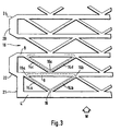
- FIG. 3 compared to FIGS. 1 and 2 can be seen that in the outer web 4 at the junction or there Junction 16 between the two connecting webs 14a and 14b there Incoming heat must take the course shown in dashed lines in Fig.
- the brick 2 is in the area of the two butt sides 10 and 12 not with a closed outer web accordingly the outer webs 4 and 6, but has a plurality of recesses 18, which by narrow strips 20 extending over the entire stone height are separated from each other.
- the perpendicular to the outer webs 4 and 6 End surfaces of the strips 20 lie in two planes, which are outside the floor plan lie in the direction of heat flow, d. H. the end regions of the strips 20 protrude from these two ground lines.
- the two levels of the floor plan in Heat flow direction are defined by two short wall sections 21, which then together with the outer webs 4 and 6 the outline or circumferential line of the Define brick 2.
- FIG. 1 the brick 2 is in the area of the two butt sides 10 and 12 not with a closed outer web accordingly the outer webs 4 and 6, but has a plurality of recesses 18, which by narrow strips 20 extending over the entire stone height are separated from each other.
- the perpendicular to the outer webs 4 and 6 End surfaces of the strips 20 lie
- the staggered arrangement of the recesses 18 and the strips 20 can the brick 2 according to the invention with another brick 2 in the area of the respective Join butt sides 10 and 12, as shown in Fig. 2.
- This tooth-like engagement of adjacent bricks 2 in the area of the butt joint there in addition to a certain stabilization of the entire masonry composite furthermore particularly preferably an increase in the thermal resistance in Area of the butt joint between two adjacent bricks.
- the tooth-like interlocking two adjacent bricks is facilitated in that each of the strips 20 two Has bevels 22 and 24, which the joining or interlocking of two Lighten brick 2.
- Brick 2 will be adjacent bricks in the area of the later butt joints crunchy, i.e. joined together without mortar. As best shown in Fig.
- the zigzag course of the connecting webs is 14 in the embodiment shown there with respect to a transverse central plane of the Brick 2 symmetrical.
- This transverse central plane of the brick 2 is shown in FIG a central inner web 28 is formed.
- This measure ensures that the 1 shown embodiment of the brick 2 according to the invention with a total thirteen inner webs 8 or 8 with an odd number of inner webs in general the number of connection points or junctions 16 on the outer web side 4 is equal to the number of nodes 16 on the outer web 6 side.
- FIG. 4 shows a representation corresponding to FIG. 1 of a brick 2 'according to a second embodiment or embodiment of the present invention. Same Reference numerals as in FIGS. 1 to 3 denote the same or corresponding ones in FIG. 4 Parts.
- the brick 2 'of FIG. 4 differs from the brick 2 according to FIG. 1 in essential in that it is no longer symmetrical to the inner web in plan view 28 of Figure 1.
- the zigzag course of the connecting webs 14 is a top view of the tile continuously from an outer web 4 or 6 to the opposite outer web 6 or 4 aligned.
- the tips of the zigzag course of the connecting webs 14 all point in a common direction (in Fig. 4 away from the outer web 6 in the direction of the outer web 4) and not starting from the one acting as a plane of symmetry Inner web 28 on both sides in the direction of the outer webs 4 and 6 (Fig. 1).
- the design of the brick 2 'according to FIG. 4 requires that instead of the symmetrical Design of the bevels 22 and 24, as in the brick 2 according to the Figures 1 to 3, which in Fig. 4 upper side of the brick 2 'is configured differently than that in Fig. 4 lower. 4, the lower side of the brick 2 '(butt side 12) has the bevels 22 and 24 to the like the brick 2 according to Figures 1 to 3 Make 20 on. On the top in Fig.
- the brick 2 'according to the second embodiment can like the brick 2 of the first embodiment regardless of its orientation in the region of the recesses 18 and strips 20 are crunched with an adjacent brick 2 ', whereby then the additional holes 26 (Fig. 2) result.
- the present invention Ziegels was based on the concrete design examples for bricks high thermal insulation and good values for sound insulation and pressure resistance.
- the present invention is Bricks are just as good in terms of optimized sound insulation or an optimized compressive strength.
- perforated bricks in particular those with long, unsupported inner webs, which for reasons improved thermal insulation with just a few connecting bars are supported, there is the problem of the long unsupported inner web areas can resonate when sound is introduced into the brick and is therefore mostly a brick that is largely optimized with regard to thermal insulation less good in terms of its sound insulation ability.
- the individual inner webs 8 are bricks by the plurality of connecting webs 14 in the area of junctions or junctions 16 evenly essentially over their entire length extension between the two abutting sides 10 and 12 supported against each other.
- a configured according to FIGS. 1 to 3 or 4 Bricks optimized as far as possible with regard to their thermal insulation capacity. 2 or 2 'according to the present invention therefore already has a very good one Sound insulation ability, since the short unsupported partial areas of the inner webs 8 cannot or only insignificantly resonate when sound is introduced, so that therefore the sound transmission through the material of the brick is low.
- the sound insulation ability of the brick according to the invention can be further optimized if necessary be without any significant drawbacks in thermal insulation must be made: to further improve the sound insulation ability more nodes 16 on the length of the inner webs 8 and the outer webs 4 and 6 are provided so that the zigzag profile of the inner web course becomes steeper. As a result, the individual inner webs 8 at even more nodes 16 over the Crosspieces 14 supported against each other, so that an even lower probability there is that portions of the inner webs 8 resonate when sound is introduced devices.
- the wall thicknesses of the connecting webs 14 In order to optimize the brick according to the invention with regard to its compressive strength, In principle, it is sufficient for the wall thicknesses of the connecting webs 14 and also that of To increase inner webs 8.
- the spacing of inner webs 8 to each other and the material or wall thicknesses of the inner webs 8 and Connecting webs 14 also depend essentially on that for the manufacture of the invention Ziegel's material used and the resulting restrictions in the mouthpiece of an extrusion system.
- the wall thickness ratio of the connecting webs 14 to the inner webs 8 is in the range from about 1: 1 to 1:10, preferably at about 1: 2.
- the wall thickness of the Inner webs are in the range of about 1 to about 12 mm, preferably about 4 to 5 mm and the wall thickness of the connecting webs is also in the range from about 1 to 12 mm, preferably about 2 to 4 mm. From the specified values upwards or below differing wall thicknesses of the inner webs 8 and the connecting webs 14 are at Special cases also possible.
- the invention is distinguished Brick in that it is both in terms of its thermal insulation capacity as well its compressive strength and soundproofing ability can be optimized without this profound modifications to the hole pattern of the brick are necessary.
- Brick is already paired with very good thermal insulation properties with good soundproofing properties and high pressure resistance. Both the Soundproofing properties as well as the compressive strength can be - without major Cutbacks in thermal insulation capacity - no problem due to a different arrangement of the Optimize connecting webs 14 with respect to the inner webs 8.
- Another advantageous property of the brick according to the invention is that despite the high proportion of holes in the brick cross-section due to the framework-like stiffening has a high stability. This is especially true in brick making by means of an extrusion system, much more than the framework-like stiffening of the individual inner webs 8 there is no danger, despite the high proportion of holes the brick strand just leaving the mouthpiece under the influence of gravity slumps. Furthermore, the high strength of the brick blank allows the later Storage areas can be ground, because the brick due to the framework Bracing the grinding wheels provides sufficient inherent stability. Such a Ground brick according to the invention can then be used in a particularly advantageous manner be glued.
Landscapes
- Engineering & Computer Science (AREA)
- Architecture (AREA)
- Physics & Mathematics (AREA)
- Electromagnetism (AREA)
- Civil Engineering (AREA)
- Structural Engineering (AREA)
- Furnace Housings, Linings, Walls, And Ceilings (AREA)
- Extraction Or Liquid Replacement (AREA)
- Harvester Elements (AREA)
- Percussion Or Vibration Massage (AREA)
- Building Environments (AREA)
- Glass Melting And Manufacturing (AREA)
Description
- Fig. 1
- eine verkleinerte Draufsicht von oben auf eine erste Ausgestaltungsform eines erfindungsgemäßen Hochlochziegels;
- Fig. 2
- eine gegenüber Fig. 1 nochmals verkleinerte Teilansicht zweier erfindungsgemäßer Hochlochziegel im Verbund;
- Fig. 3
- eine gegenüber Fig. 1 und Fig. 2 vergrößerte Teilansicht eines erfindungsgemäßen Hochlochziegels zur Erläuterung des Prinzips der Vergrößerung des Wärmeleitungsweges; und
- Fig. 4
- eine Fig. 1 entsprechende Darstellung einer zweiten Ausgestaltungsform eines erfindungsgemäßen Hochlochziegels.
Claims (11)
- Hochlochziegel mit:wobei die Stoßseiten (10, 12) Außenstege aufweisen, welche mehrfach derart unterbrochen sind, daß sie schmale, über die Steinhöhe reichende Leisten (20) aufweisen, zwischen denen taschenartige, über die gesamte Ziegelhöhe verlaufende Ausnehmungen (18) vorgesehen sind, wobei die schmalen Leisten (20) bzw. taschenartigen Ausnehmungen (18) in den beiden Außenstegen in Ziegeldraufsicht gesehen zueinander versetzt sind,zwei parallelen Außenstegen (4, 6) und hierzu senkrecht verlaufenden, parallelen Stoßseiten (10, 12), wobei die Außenstege (4, 6) und die Stoßseiten (10, 12) die Umfangswände des Steins bilden; undeiner Mehrzahl von geraden, zu den Außenstegen parallelen Innenstegen (8), welche vorzugsweise über die senkrecht zu den Stoßseiten (10, 12) gemessene Breite des Ziegels (2) sowie über die Ziegelhöhe durchlaufen, wobei die geraden Innenstege (8) durch Verbindungsstege (14) miteinander verbunden und gegeneinander abgestützt sind,
dadurch gekennzeichnet, daß die schmalen Leisten (20) bzw. taschenartigen Ausnehmungen (18) in den beiden Außenstegen in Ziegeldraufsicht gesehen so zueinander versetzt sind, daß im Bereich der Stoßseiten (10, 12) aneinandergesetzte Ziegel (2) derart zahnartig ineinandergreifen, daß sich ein Steg einfacher Breite ergibt. - Hochlochziegel nach Anspruch 1, dadurch gekennzeichnet, daß die schmalen Leisten (20) mit ihren Endabschnitten über die stoßseitenseitig verlaufenden, durch Wandabschnitte (21) definierte Grundrißlinien des Steins (2) hinausragen.
- Hochlochziegel nach Anspruch 1 oder 2, dadurch gekennzeichnet, daß die schmalen Leisten (20) beidseitig Abschrägungen (22, 24; 28, 30) aufweisen.
- Hochlochziegel nach einem der Ansprüche 1 bis 3, dadurch gekennzeichnet, daß die Verbindung der Innenstege (8) mittels der Verbindungsstege (14) fachwerkartig derart erfolgt, daß die durch die Anschlußstellen der Verbindungsstege (14) an den Innenstegen (8) gebildeten Knotenpunkte (16) in einem quer zur Verlaufsrichtung der Innenstege (8) liegenden Abstand voneinander angeordnet sind.
- Hochlochziegel nach einem der Ansprüche 1 bis 4, dadurch gekennzeichnet, daß die Verbindungsstege (14) zwischen zwei einander benachbarten Innenstegen (8) im Zickzack verlaufen.
- Hochlochziegel nach einem der Ansprüche 1 bis 5, dadurch gekennzeichnet, daß die durch die Knotenpunkte (16) gebildeten Spitzen und Fußpunkte von Verbindungsstegen (14) zu beiden Seiten eines Innensteges (8) im Abstand voneinander liegen.
- Hochlochziegel nach Anspruch 6, dadurch gekennzeichnet, daß die durch die Knotenpunkte (16) gebildeten Spitzen von Verbindungsstegen (14) auf einer Seite eines Innensteges (8) mittig zwischen den durch die Knotenpunkte (16) gebildeten Fußpunkte von Verbindungsstegen (14) auf der gegenüberliegenden Seite des Innensteges (8) liegen.
- Hochlochziegel nach Anspruch 5, dadurch gekennzeichnet, daß der Zickzack-Verlauf der Verbindungsstege (14) in Ziegeldraufsicht zu einer Quermittelebene (28) des Ziegels (2) symmetrisch ist.
- Hochlochziegel nach Anspruch 5, dadurch gekennzeichnet, daß der Zickzack-Verlauf der Verbindungsstege (14) in Ziegeldraufsicht durchgehend von einem Außensteg (4, 6) zum gegenüberliegenden Außensteg (6, 4) weisend ausgerichtet ist.
- Hochlochziegel nach einem der Ansprüche 1 bis 9, dadurch gekennzeichnet, daß das Wandstärkenverhältnis von Verbindungsstegen (14) zu Innenstegen (8) im Bereich von 1 : 1 bis 1 : 10, bevorzugt bei etwa 1 : 2 liegt.
- Hochlochziegel nach einem der Ansprüche 1 bis 10, dadurch gekennzeichnet, daß die Wandstärke der Innenstege (8) im Bereich von etwa 1 bis 12, bevorzugt bei etwa 4 bis 5 mm liegt und daß die Wandstärke der Verbindungsstege (14) im Bereich von etwa 1 bis 12, bevorzugt bei etwa 2 bis 4 mm liegt.
Applications Claiming Priority (3)
| Application Number | Priority Date | Filing Date | Title |
|---|---|---|---|
| DE9400942U | 1994-01-20 | ||
| DE9400942U DE9400942U1 (de) | 1994-01-20 | 1994-01-20 | Hochlochziegel |
| EP94119516A EP0668412B1 (de) | 1994-01-20 | 1994-12-09 | Hochlochziegel |
Related Parent Applications (2)
| Application Number | Title | Priority Date | Filing Date |
|---|---|---|---|
| EP94119516.6 Division | 1994-12-09 | ||
| EP94119516A Division EP0668412B1 (de) | 1994-01-20 | 1994-12-09 | Hochlochziegel |
Publications (2)
| Publication Number | Publication Date |
|---|---|
| EP0905329A1 EP0905329A1 (de) | 1999-03-31 |
| EP0905329B1 true EP0905329B1 (de) | 2003-04-02 |
Family
ID=6903482
Family Applications (2)
| Application Number | Title | Priority Date | Filing Date |
|---|---|---|---|
| EP94119516A Expired - Lifetime EP0668412B1 (de) | 1994-01-20 | 1994-12-09 | Hochlochziegel |
| EP98124767A Expired - Lifetime EP0905329B1 (de) | 1994-01-20 | 1994-12-09 | Hochlochziegel |
Family Applications Before (1)
| Application Number | Title | Priority Date | Filing Date |
|---|---|---|---|
| EP94119516A Expired - Lifetime EP0668412B1 (de) | 1994-01-20 | 1994-12-09 | Hochlochziegel |
Country Status (3)
| Country | Link |
|---|---|
| EP (2) | EP0668412B1 (de) |
| AT (2) | ATE236310T1 (de) |
| DE (3) | DE9400942U1 (de) |
Families Citing this family (6)
| Publication number | Priority date | Publication date | Assignee | Title |
|---|---|---|---|---|
| AT409010B (de) * | 1996-11-28 | 2002-05-27 | Leitl Ziegel Ges M B H | Hochlochziegel |
| DE19807040C5 (de) * | 1998-02-19 | 2010-03-25 | Schlagmann Baustoffwerke Gmbh & Co Kg | Wärmedämmverfüllziegel |
| AT500731B1 (de) * | 2004-06-29 | 2006-11-15 | Zipfinger Mechatronik Gmbh | Hochlochziegel, verfahren zur herstellung und mundstück |
| DE102010016877A1 (de) | 2010-05-11 | 2011-11-17 | Michael Kellerer | Mauerziegel mit Dämmfüllung |
| RU170719U1 (ru) * | 2017-01-24 | 2017-05-04 | Акционерное Общество "Самарский комбинат керамических материалов" (АО "Самарский комбинат керамических материалов") | Формованное изделие |
| RU2652224C1 (ru) * | 2017-03-06 | 2018-04-25 | Акционерное Общество "Самарский комбинат керамических материалов" (АО "Самарский комбинат керамических материалов") | Способ формования изделия и формовочное устройство для его осуществления |
Family Cites Families (8)
| Publication number | Priority date | Publication date | Assignee | Title |
|---|---|---|---|---|
| GB434127A (en) * | 1934-02-23 | 1935-08-23 | Leslie Eric Hamson | Improvements in building and refractory bricks or blocks |
| AT276706B (de) * | 1968-04-12 | 1969-12-10 | Wienerberger Baustoffind Ag | Stranggepreßter Hohlziegel |
| AT339018B (de) * | 1975-09-09 | 1977-09-26 | Wienerberger Baustoffind Ag | Stranggepresster hohlziegel |
| DE7926189U1 (de) * | 1978-10-12 | 1981-01-08 | Katholnigg, Roland, Ing., Innsbruck (Oesterreich) | Stranggepresster hohlziegel |
| DE3030846C2 (de) * | 1980-08-14 | 1983-03-24 | Johann 8081 Oberweikertshofen Kellerer | Hochlochziegel |
| DE8138174U1 (de) * | 1981-02-23 | 1982-08-26 | Rieseneder Gesellschaft mbH & Co KG, 4041 Linz | Stranggepresster hohlziegel |
| DE8900283U1 (de) * | 1989-01-11 | 1989-04-20 | Deutsche Poroton GmbH, 4630 Bochum | Großformatiger Schallschutzziegel |
| DE4228087A1 (de) * | 1992-08-24 | 1994-03-03 | Raimund Rimmele | Hochlochziegel |
-
1994
- 1994-01-20 DE DE9400942U patent/DE9400942U1/de not_active Expired - Lifetime
- 1994-12-09 DE DE59410266T patent/DE59410266D1/de not_active Expired - Lifetime
- 1994-12-09 AT AT98124767T patent/ATE236310T1/de active
- 1994-12-09 EP EP94119516A patent/EP0668412B1/de not_active Expired - Lifetime
- 1994-12-09 DE DE59408518T patent/DE59408518D1/de not_active Expired - Lifetime
- 1994-12-09 AT AT94119516T patent/ATE182386T1/de active
- 1994-12-09 EP EP98124767A patent/EP0905329B1/de not_active Expired - Lifetime
Also Published As
| Publication number | Publication date |
|---|---|
| DE59408518D1 (de) | 1999-08-26 |
| DE9400942U1 (de) | 1995-01-26 |
| ATE236310T1 (de) | 2003-04-15 |
| EP0905329A1 (de) | 1999-03-31 |
| ATE182386T1 (de) | 1999-08-15 |
| EP0668412A1 (de) | 1995-08-23 |
| EP0668412B1 (de) | 1999-07-21 |
| DE59410266D1 (de) | 2003-05-08 |
Similar Documents
| Publication | Publication Date | Title |
|---|---|---|
| AT410688B (de) | Bauelement | |
| CH638265A5 (de) | Verbandsmauerwerk. | |
| EP0905329B1 (de) | Hochlochziegel | |
| DE19807040B4 (de) | Wärmedämmverfüllziegel | |
| DE4143387C2 (de) | Verfahren zum Herstellen von Formkörpern, insbesondere von Dämmplatten | |
| EP2386696B1 (de) | Mauerziegel mit Dämmfüllung | |
| EP1088941B1 (de) | Enwässerungsrinne sowie Rinnenelement hierfür | |
| DE3100425C2 (de) | Mauerwerk und für den Zusammenhalt der Bausteine geeignetes Profilstreifensystem | |
| DE102009045329B4 (de) | Hochlochziegel | |
| DE3343287A1 (de) | Hochlochziegel | |
| DE3030846C2 (de) | Hochlochziegel | |
| EP0606625B1 (de) | Hintermauerziegel | |
| EP3577286B1 (de) | Bausystem | |
| EP1323876B1 (de) | Tafelförmiges Bauelement, dafür geeigneter Abstandshalter und Rippenpaarträger, damit errichtetes Bauwerk und Verfahren zu seiner Errichtung | |
| DE4341440C2 (de) | Ziegelstein | |
| DE3402541A1 (de) | Gelochter stein, insbesondere grossblockziegel | |
| EP1428954A1 (de) | Leicht-Hochlochziegel | |
| EP0909857B1 (de) | Leicht-Hochlochziegel | |
| AT500731B1 (de) | Hochlochziegel, verfahren zur herstellung und mundstück | |
| DE19804729A1 (de) | Baustein, insbesondere auf der Basis zementgebundenen Blähtons | |
| EP3662110B1 (de) | Verbesserte verlegeeinheit für ein segmentbogenpflaster | |
| DE866382C (de) | Baustein und Bausteinanordnung | |
| DE19944672C2 (de) | Wärmedämm-Mauerstein | |
| DE818106C (de) | Ziegel oder anderer Baukoerper | |
| AT378216B (de) | Bewehrungsmatte fuer stahlbeton |
Legal Events
| Date | Code | Title | Description |
|---|---|---|---|
| PUAI | Public reference made under article 153(3) epc to a published international application that has entered the european phase |
Free format text: ORIGINAL CODE: 0009012 |
|
| AC | Divisional application: reference to earlier application |
Ref document number: 668412 Country of ref document: EP |
|
| AK | Designated contracting states |
Kind code of ref document: A1 Designated state(s): AT CH DE FR IT LI |
|
| 17P | Request for examination filed |
Effective date: 19990921 |
|
| 17Q | First examination report despatched |
Effective date: 20001020 |
|
| GRAH | Despatch of communication of intention to grant a patent |
Free format text: ORIGINAL CODE: EPIDOS IGRA |
|
| GRAH | Despatch of communication of intention to grant a patent |
Free format text: ORIGINAL CODE: EPIDOS IGRA |
|
| GRAA | (expected) grant |
Free format text: ORIGINAL CODE: 0009210 |
|
| AC | Divisional application: reference to earlier application |
Ref document number: 0668412 Country of ref document: EP Kind code of ref document: P |
|
| AK | Designated contracting states |
Designated state(s): AT CH DE FR IT LI |
|
| REG | Reference to a national code |
Ref country code: CH Ref legal event code: NV Representative=s name: ISLER & PEDRAZZINI AG Ref country code: CH Ref legal event code: EP |
|
| REF | Corresponds to: |
Ref document number: 59410266 Country of ref document: DE Date of ref document: 20030508 Kind code of ref document: P |
|
| ET | Fr: translation filed | ||
| PLBE | No opposition filed within time limit |
Free format text: ORIGINAL CODE: 0009261 |
|
| STAA | Information on the status of an ep patent application or granted ep patent |
Free format text: STATUS: NO OPPOSITION FILED WITHIN TIME LIMIT |
|
| 26N | No opposition filed |
Effective date: 20040105 |
|
| REG | Reference to a national code |
Ref country code: CH Ref legal event code: PCAR Free format text: ISLER & PEDRAZZINI AG;POSTFACH 1772;8027 ZUERICH (CH) |
|
| PGFP | Annual fee paid to national office [announced via postgrant information from national office to epo] |
Ref country code: DE Payment date: 20121207 Year of fee payment: 19 Ref country code: CH Payment date: 20121220 Year of fee payment: 19 |
|
| PGFP | Annual fee paid to national office [announced via postgrant information from national office to epo] |
Ref country code: IT Payment date: 20121214 Year of fee payment: 19 |
|
| PGFP | Annual fee paid to national office [announced via postgrant information from national office to epo] |
Ref country code: AT Payment date: 20121221 Year of fee payment: 19 |
|
| PGFP | Annual fee paid to national office [announced via postgrant information from national office to epo] |
Ref country code: FR Payment date: 20130117 Year of fee payment: 19 |
|
| REG | Reference to a national code |
Ref country code: DE Ref legal event code: R119 Ref document number: 59410266 Country of ref document: DE |
|
| REG | Reference to a national code |
Ref country code: CH Ref legal event code: PL |
|
| REG | Reference to a national code |
Ref country code: AT Ref legal event code: MM01 Ref document number: 236310 Country of ref document: AT Kind code of ref document: T Effective date: 20131209 |
|
| REG | Reference to a national code |
Ref country code: FR Ref legal event code: ST Effective date: 20140829 |
|
| REG | Reference to a national code |
Ref country code: DE Ref legal event code: R119 Ref document number: 59410266 Country of ref document: DE Effective date: 20140701 |
|
| PG25 | Lapsed in a contracting state [announced via postgrant information from national office to epo] |
Ref country code: CH Free format text: LAPSE BECAUSE OF NON-PAYMENT OF DUE FEES Effective date: 20131231 Ref country code: DE Free format text: LAPSE BECAUSE OF NON-PAYMENT OF DUE FEES Effective date: 20140701 Ref country code: LI Free format text: LAPSE BECAUSE OF NON-PAYMENT OF DUE FEES Effective date: 20131231 |
|
| PG25 | Lapsed in a contracting state [announced via postgrant information from national office to epo] |
Ref country code: AT Free format text: LAPSE BECAUSE OF NON-PAYMENT OF DUE FEES Effective date: 20131209 Ref country code: FR Free format text: LAPSE BECAUSE OF NON-PAYMENT OF DUE FEES Effective date: 20131231 |
|
| PG25 | Lapsed in a contracting state [announced via postgrant information from national office to epo] |
Ref country code: IT Free format text: LAPSE BECAUSE OF NON-PAYMENT OF DUE FEES Effective date: 20131209 |