EP0905387A2 - Ruban de clous et rouleau de ruban pour une machine à clouer - Google Patents
Ruban de clous et rouleau de ruban pour une machine à clouer Download PDFInfo
- Publication number
- EP0905387A2 EP0905387A2 EP98104659A EP98104659A EP0905387A2 EP 0905387 A2 EP0905387 A2 EP 0905387A2 EP 98104659 A EP98104659 A EP 98104659A EP 98104659 A EP98104659 A EP 98104659A EP 0905387 A2 EP0905387 A2 EP 0905387A2
- Authority
- EP
- European Patent Office
- Prior art keywords
- nail
- nails
- heads
- coil
- wires
- Prior art date
- Legal status (The legal status is an assumption and is not a legal conclusion. Google has not performed a legal analysis and makes no representation as to the accuracy of the status listed.)
- Granted
Links
Images


Classifications
-
- B—PERFORMING OPERATIONS; TRANSPORTING
- B25—HAND TOOLS; PORTABLE POWER-DRIVEN TOOLS; MANIPULATORS
- B25C—HAND-HELD NAILING OR STAPLING TOOLS; MANUALLY OPERATED PORTABLE STAPLING TOOLS
- B25C1/00—Hand-held nailing tools; Nail feeding devices
- B25C1/001—Nail feeding devices
- B25C1/003—Nail feeding devices for belts of nails
-
- F—MECHANICAL ENGINEERING; LIGHTING; HEATING; WEAPONS; BLASTING
- F16—ENGINEERING ELEMENTS AND UNITS; GENERAL MEASURES FOR PRODUCING AND MAINTAINING EFFECTIVE FUNCTIONING OF MACHINES OR INSTALLATIONS; THERMAL INSULATION IN GENERAL
- F16B—DEVICES FOR FASTENING OR SECURING CONSTRUCTIONAL ELEMENTS OR MACHINE PARTS TOGETHER, e.g. NAILS, BOLTS, CIRCLIPS, CLAMPS, CLIPS OR WEDGES; JOINTS OR JOINTING
- F16B15/00—Nails; Staples
- F16B15/08—Nails; Staples formed in integral series but easily separable
Definitions
- the invention relates to a coilable nail tape Steel nails joined by at least two wires are connected, as well as a nail ribbon coil and a nail device.
- Such a nail magazine contains up to 140 aligned in parallel Nails that are connected by a wire to the nail shafts e.g. is welded together. Through the The deformability of the wire can be obtained in this way Roll up the nail tape into a coil, in whatever form it is in an appropriate nailing device is used.
- Bel den previous embodiments existed the connecting wires made of soft unalloyed metals, which is a flawless Coiling and welding the wire-nail connection allow. Processing of this embodiment using a nail device is difficult or not at all possible because it is compressed by the stroke movement the nail gaps come. Furthermore, the nails are laying Magazine center around.
- the object of the present invention is also a to create coilable nail tape that this twisting counteracts or tilting of the nails and a safe
- the nails are separated from the wires in the nailing device the hammer element ensures, and thus a trouble-free enables fast work.
- the nail ribbon coil and the nail device to be designed in such a way that tilting of the nail band is prevented becomes.
- the task becomes solved that for nails with a length of 14 to 25 mm and a shaft diameter of 2 to 3 mm, preferably 2.5 mm, the wires a distance of 6.5 to 7.5 mm, preferably 7 mm from each other.
- this distance is small enough that the hammer element of the nail device on both Use a nail to join the wires can and thus a safe detachment of the nail from the Wires is guaranteed.
- the nails preferably have heads and those close to the head
- Wire is preferably 9 to 11 mm apart 10 mm, attached from the head to the shafts of the nails. This Distance of the wire close to the head to the head ensures that it is flawless Separate the nail from the wires.
- the wire near the head is at a distance from the head of the nail that corresponds to the diameter of the head.
- this contains Nail tape 70 to 85, preferably 80, nails, on the one hand prevents frequent reloading of the nailing device and on the other hand, the size and weight of the nail magazine is limited.
- a limitation of the coil is the weight of the nail tape and given the magazine size.
- the nails are opposite the vertical on the wires preferably inclined by about 15 °.
- a winding tube is provided in the axis of the coil, whose outer diameter is the inner diameter of the coil corresponds and their cylindrical surface on the nail shafts, with the exemption of the nail heads or on the wires of the innermost coilage is present.
- the winding tube is a Cylinder and arranged at a distance from the magazine bottom, so that the nail heads of the inner coilage are free and protrude inwards under the winding tube.
- the winding sleeve has a nail heads receiving annular groove.
- the present invention also relates to the nail ribbon coil for use in such a nailing device, the coil has the described features.
- FIG. 1 is a top view of one Part of a nailing device
- Fig. 2 is a section along the line II-II in Fig. 1
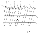
- Fig. 3 is a broken supervision the nail tape.
- FIG. 1 shows the top view of the magazine of a nailing device, as disclosed in EP 0 321 440.
- the other parts of the nailing device not relevant here as well the cover for the magazine are the simpler Not shown for illustration.
- the nail tape coil 7 is located in magazine 6 and consists of a series of nails 5, which are separated by two Connecting wires 2,3 connected to a band are. The end area of the coil is shown, ie a lot of the nails have already been used.
- the magazine bottom is designated 8, and over half of the Magazine extends the magazine wall 9. By a the magazine can be designed analogously be closed, the nail tape through an opening 10 to the hammer head, not shown here, emerges.
- a winding tube 11 provided that with the coil 7 on the spindle 12 of the Magazine is rotatably attached.
- the winding tube has in a version on one side, namely on the Magazine bottom 8 facing side, an annular groove 13 on, which allows a recording of the nail heads 4.
- Dashed with the line 14 is the course of the bottom of the Wrapping sleeve drawn in if after another execution instead of the groove simply use the winding tube as Cylinder is provided, which is inserted into the coil is that the nail heads 4 are below the winding tube, so that the nail heads are free.
- Fig.2 is a section along the line II-II in Fig.1 shown, with a second layer on the left side of the coil is drawn.
- the alternative annular groove 13 is formed so deep that the nail heads 4 have enough space.
- the nail ribbon coil can either open from the very beginning the winding tube must be wound so that the coil with the Winding sleeve is attached.
- the winding tube can also provided separately as an accessory for the nail device be, the winding tube in the prepared nail tape coil is inserted in the middle.
- the height of the winding tube corresponds approximately to the height of the Nail tape. In any case, it must be guaranteed that the Nails of the inner coil layer or their two connecting wires 2,3 rest on the cylindrical surface of the winding tube.
- the nail tape is designed so that several Nails 1 with heads 4 and shafts 5 parallel to each other aligned and by means of two wires 2, 3 with each other are connected.
- the wires 2, 3 have a distance d from each other.
- the wire 2 near the head has 4 of the heads the nails 1 a distance e, their diameter f Heads 4 are alike.
- the shafts 5 of the nails 1 are opposite the perpendicular to the wires 2, 3 inclined by 15 °.
- the wires are tempered, is their hardness changed and the deflection and compression are limited. But this in turn means that the Possibility of movement of the nails to be introduced better are controllable and predictable and a flawless one Feeding the nail tape is guaranteed.
- the remuneration can e.g. by stretching the wires at about 40 to 60 kp Tensile force.
Landscapes
- Engineering & Computer Science (AREA)
- General Engineering & Computer Science (AREA)
- Mechanical Engineering (AREA)
- Portable Nailing Machines And Staplers (AREA)
- Dovetailed Work, And Nailing Machines And Stapling Machines For Wood (AREA)
Priority Applications (2)
| Application Number | Priority Date | Filing Date | Title |
|---|---|---|---|
| US09/159,647 US6557703B1 (en) | 1997-09-24 | 1998-09-24 | Coil strap with nails for use in a nail hammer |
| US10/226,343 US6896135B2 (en) | 1997-09-24 | 2002-08-23 | Coil strap with nails for use in a nail hammer |
Applications Claiming Priority (6)
| Application Number | Priority Date | Filing Date | Title |
|---|---|---|---|
| AT59697U AT2657U1 (de) | 1997-09-24 | 1997-09-24 | Coillierbares nagelband mit nägeln |
| AT59697U | 1997-09-24 | ||
| AT596/97 | 1997-09-24 | ||
| AT1898U | 1998-01-15 | ||
| AT18/98 | 1998-01-15 | ||
| AT0001898U AT2548U1 (de) | 1998-01-15 | 1998-01-15 | Coillierbares nagelband mit nägeln |
Publications (3)
| Publication Number | Publication Date |
|---|---|
| EP0905387A2 true EP0905387A2 (fr) | 1999-03-31 |
| EP0905387A3 EP0905387A3 (fr) | 1999-05-19 |
| EP0905387B1 EP0905387B1 (fr) | 2001-09-19 |
Family
ID=25591130
Family Applications (1)
| Application Number | Title | Priority Date | Filing Date |
|---|---|---|---|
| EP98104659A Expired - Lifetime EP0905387B1 (fr) | 1997-09-24 | 1998-03-16 | Ruban de clous et rouleau de ruban pour une machine à clouer |
Country Status (3)
| Country | Link |
|---|---|
| EP (1) | EP0905387B1 (fr) |
| AT (1) | ATE205917T1 (fr) |
| DE (1) | DE59801505D1 (fr) |
Cited By (1)
| Publication number | Priority date | Publication date | Assignee | Title |
|---|---|---|---|---|
| US6896135B2 (en) | 1997-09-24 | 2005-05-24 | Helmut Leitner | Coil strap with nails for use in a nail hammer |
Family Cites Families (5)
| Publication number | Priority date | Publication date | Assignee | Title |
|---|---|---|---|---|
| US3167778A (en) * | 1962-10-17 | 1965-02-02 | United Shoe Machinery Corp | Fastener packages |
| US3330462A (en) * | 1966-05-09 | 1967-07-11 | Bostitch Inc | Fastener driving apparatus |
| US3587842A (en) * | 1969-11-10 | 1971-06-28 | Spotnails | Cartridge of collated fasteners |
| EP0118177B1 (fr) * | 1983-02-07 | 1987-12-02 | Stanley-Bostitch, Inc. | Assemblage enroulé en spirale des moyens de fixation connectés |
| US5456635A (en) * | 1994-02-22 | 1995-10-10 | Monacelli; Umberto | Method and apparatus for producing assemblies of headed fasteners |
-
1998
- 1998-03-16 EP EP98104659A patent/EP0905387B1/fr not_active Expired - Lifetime
- 1998-03-16 DE DE59801505T patent/DE59801505D1/de not_active Expired - Lifetime
- 1998-03-16 AT AT98104659T patent/ATE205917T1/de not_active IP Right Cessation
Cited By (1)
| Publication number | Priority date | Publication date | Assignee | Title |
|---|---|---|---|---|
| US6896135B2 (en) | 1997-09-24 | 2005-05-24 | Helmut Leitner | Coil strap with nails for use in a nail hammer |
Also Published As
| Publication number | Publication date |
|---|---|
| EP0905387A3 (fr) | 1999-05-19 |
| DE59801505D1 (de) | 2001-10-25 |
| EP0905387B1 (fr) | 2001-09-19 |
| ATE205917T1 (de) | 2001-10-15 |
Similar Documents
| Publication | Publication Date | Title |
|---|---|---|
| DE2712294C3 (de) | Vorrichtung an Werkzeugen zum Eintreiben von Befestigungsmitteln | |
| DE4310757B4 (de) | Objekt-Haltevorrichtung | |
| DE60307862T2 (de) | Positioniervorrichtung für nägel | |
| DE2463447C2 (fr) | ||
| EP2051835B1 (fr) | Dispositif de clouage | |
| DE3806624A1 (de) | Traegerstreifen | |
| DE2750562C2 (de) | Zu einem Nagelstreifen vereinigte Nägel und Werkzeug zum Eintreiben der Nägel | |
| DE3414082A1 (de) | Befestigungselement, bestehend aus einem stift und einem rohrfoermigen glied | |
| DE69524391T2 (de) | Montageverfahren für einen käfiglosen schlitten einer linearführung | |
| DE2034145A1 (de) | Nagel | |
| DE3506421A1 (de) | Nageleintreibgeraet mit im querschnitt zentralsymmetrischem treiber | |
| DE2533672C3 (de) | Nietenvorratsband und Verfahren zu dessen Herstellung | |
| DE3816593C2 (fr) | ||
| EP0905387A2 (fr) | Ruban de clous et rouleau de ruban pour une machine à clouer | |
| DE19859130A1 (de) | Befestigungselement | |
| DE69412411T2 (de) | Methode und Gerät zum Formen eines Kopfes an einem Befestigungselement | |
| DE4406556C1 (de) | Mit Bolzen bestücktes Magazin für ein pulverkraftbetriebenes Setzgerät | |
| EP0929268B1 (fr) | Appareil dentaire a verin median | |
| DE2063265B2 (de) | Vorschubeinrichtung fur ein Eintreibwerkzeug zum Zuführen von Nageln o.dgl | |
| DE10115369A1 (de) | Magazin für Befestigungselemente | |
| EP0352531B1 (fr) | Aiguille à tirage | |
| EP3855462B1 (fr) | Dispositif et procédé d'enroulement sans chargeur de noyaux toroïdaux | |
| DE1988039U (de) | Werkzeug zum setzen von blindnieten. | |
| DE1809460B2 (de) | Türfeststeller, insbesondere für Kraftwagentüren | |
| DE607196C (de) | Druckstempel fuer Druckknopfkugelteile |
Legal Events
| Date | Code | Title | Description |
|---|---|---|---|
| PUAI | Public reference made under article 153(3) epc to a published international application that has entered the european phase |
Free format text: ORIGINAL CODE: 0009012 |
|
| AK | Designated contracting states |
Kind code of ref document: A2 Designated state(s): AT BE DE FR GB IT NL SE |
|
| AX | Request for extension of the european patent |
Free format text: AL;LT;LV;MK;RO;SI |
|
| PUAL | Search report despatched |
Free format text: ORIGINAL CODE: 0009013 |
|
| AK | Designated contracting states |
Kind code of ref document: A3 Designated state(s): AT BE CH DE DK ES FI FR GB GR IE IT LI LU MC NL PT SE |
|
| AX | Request for extension of the european patent |
Free format text: AL;LT;LV;MK;RO;SI |
|
| 17P | Request for examination filed |
Effective date: 19991009 |
|
| AKX | Designation fees paid |
Free format text: AT BE CH DE DK ES FI FR GB LI |
|
| RBV | Designated contracting states (corrected) |
Designated state(s): AT BE DE FR GB IT NL SE |
|
| 17Q | First examination report despatched |
Effective date: 20000810 |
|
| GRAG | Despatch of communication of intention to grant |
Free format text: ORIGINAL CODE: EPIDOS AGRA |
|
| GRAG | Despatch of communication of intention to grant |
Free format text: ORIGINAL CODE: EPIDOS AGRA |
|
| GRAH | Despatch of communication of intention to grant a patent |
Free format text: ORIGINAL CODE: EPIDOS IGRA |
|
| GRAG | Despatch of communication of intention to grant |
Free format text: ORIGINAL CODE: EPIDOS AGRA |
|
| GRAH | Despatch of communication of intention to grant a patent |
Free format text: ORIGINAL CODE: EPIDOS IGRA |
|
| GRAA | (expected) grant |
Free format text: ORIGINAL CODE: 0009210 |
|
| AK | Designated contracting states |
Kind code of ref document: B1 Designated state(s): AT BE DE FR GB IT NL SE |
|
| PG25 | Lapsed in a contracting state [announced via postgrant information from national office to epo] |
Ref country code: NL Free format text: LAPSE BECAUSE OF FAILURE TO SUBMIT A TRANSLATION OF THE DESCRIPTION OR TO PAY THE FEE WITHIN THE PRESCRIBED TIME-LIMIT Effective date: 20010919 |
|
| REF | Corresponds to: |
Ref document number: 205917 Country of ref document: AT Date of ref document: 20011015 Kind code of ref document: T |
|
| REF | Corresponds to: |
Ref document number: 59801505 Country of ref document: DE Date of ref document: 20011025 |
|
| REG | Reference to a national code |
Ref country code: GB Ref legal event code: IF02 |
|
| GBT | Gb: translation of ep patent filed (gb section 77(6)(a)/1977) |
Effective date: 20011220 |
|
| ET | Fr: translation filed | ||
| NLV1 | Nl: lapsed or annulled due to failure to fulfill the requirements of art. 29p and 29m of the patents act | ||
| PLBE | No opposition filed within time limit |
Free format text: ORIGINAL CODE: 0009261 |
|
| STAA | Information on the status of an ep patent application or granted ep patent |
Free format text: STATUS: NO OPPOSITION FILED WITHIN TIME LIMIT |
|
| 26N | No opposition filed | ||
| PG25 | Lapsed in a contracting state [announced via postgrant information from national office to epo] |
Ref country code: IT Free format text: LAPSE BECAUSE OF NON-PAYMENT OF DUE FEES Effective date: 20050316 |
|
| PGFP | Annual fee paid to national office [announced via postgrant information from national office to epo] |
Ref country code: BE Payment date: 20060331 Year of fee payment: 9 |
|
| PG25 | Lapsed in a contracting state [announced via postgrant information from national office to epo] |
Ref country code: SE Free format text: LAPSE BECAUSE OF NON-PAYMENT OF DUE FEES Effective date: 20070317 |
|
| EUG | Se: european patent has lapsed | ||
| GBPC | Gb: european patent ceased through non-payment of renewal fee |
Effective date: 20070316 |
|
| BERE | Be: lapsed |
Owner name: *LEITNER HELMUT Effective date: 20070331 |
|
| PG25 | Lapsed in a contracting state [announced via postgrant information from national office to epo] |
Ref country code: BE Free format text: LAPSE BECAUSE OF NON-PAYMENT OF DUE FEES Effective date: 20070331 |
|
| PGFP | Annual fee paid to national office [announced via postgrant information from national office to epo] |
Ref country code: SE Payment date: 20060309 Year of fee payment: 9 |
|
| PG25 | Lapsed in a contracting state [announced via postgrant information from national office to epo] |
Ref country code: GB Free format text: LAPSE BECAUSE OF NON-PAYMENT OF DUE FEES Effective date: 20070316 |
|
| PGFP | Annual fee paid to national office [announced via postgrant information from national office to epo] |
Ref country code: GB Payment date: 20060315 Year of fee payment: 9 |
|
| PGFP | Annual fee paid to national office [announced via postgrant information from national office to epo] |
Ref country code: FR Payment date: 20100322 Year of fee payment: 13 |
|
| PGFP | Annual fee paid to national office [announced via postgrant information from national office to epo] |
Ref country code: AT Payment date: 20100325 Year of fee payment: 13 |
|
| PGFP | Annual fee paid to national office [announced via postgrant information from national office to epo] |
Ref country code: DE Payment date: 20100330 Year of fee payment: 13 |
|
| PGFP | Annual fee paid to national office [announced via postgrant information from national office to epo] |
Ref country code: IT Payment date: 20080225 Year of fee payment: 11 |
|
| PGRI | Patent reinstated in contracting state [announced from national office to epo] |
Ref country code: IT Effective date: 20110616 |
|
| PG25 | Lapsed in a contracting state [announced via postgrant information from national office to epo] |
Ref country code: AT Free format text: LAPSE BECAUSE OF NON-PAYMENT OF DUE FEES Effective date: 20110316 |
|
| REG | Reference to a national code |
Ref country code: FR Ref legal event code: ST Effective date: 20111130 |
|
| PG25 | Lapsed in a contracting state [announced via postgrant information from national office to epo] |
Ref country code: FR Free format text: LAPSE BECAUSE OF NON-PAYMENT OF DUE FEES Effective date: 20110331 Ref country code: DE Free format text: LAPSE BECAUSE OF NON-PAYMENT OF DUE FEES Effective date: 20111001 |
|
| REG | Reference to a national code |
Ref country code: DE Ref legal event code: R119 Ref document number: 59801505 Country of ref document: DE Effective date: 20111001 |
|
| PGRI | Patent reinstated in contracting state [announced from national office to epo] |
Ref country code: IT Effective date: 20110616 |