EP0905739A2 - Tube à rayons cathodiques - Google Patents
Tube à rayons cathodiques Download PDFInfo
- Publication number
- EP0905739A2 EP0905739A2 EP98117321A EP98117321A EP0905739A2 EP 0905739 A2 EP0905739 A2 EP 0905739A2 EP 98117321 A EP98117321 A EP 98117321A EP 98117321 A EP98117321 A EP 98117321A EP 0905739 A2 EP0905739 A2 EP 0905739A2
- Authority
- EP
- European Patent Office
- Prior art keywords
- grid
- voltage
- electrode
- cathode
- electrodes
- Prior art date
- Legal status (The legal status is an assumption and is not a legal conclusion. Google has not performed a legal analysis and makes no representation as to the accuracy of the status listed.)
- Withdrawn
Links
Images

Classifications
-
- H—ELECTRICITY
- H01—ELECTRIC ELEMENTS
- H01J—ELECTRIC DISCHARGE TUBES OR DISCHARGE LAMPS
- H01J29/00—Details of cathode-ray tubes or of electron-beam tubes of the types covered by group H01J31/00
- H01J29/46—Arrangements of electrodes and associated parts for generating or controlling the ray or beam, e.g. electron-optical arrangement
- H01J29/48—Electron guns
- H01J29/488—Schematic arrangements of the electrodes for beam forming; Place and form of the elecrodes
-
- H—ELECTRICITY
- H01—ELECTRIC ELEMENTS
- H01J—ELECTRIC DISCHARGE TUBES OR DISCHARGE LAMPS
- H01J29/00—Details of cathode-ray tubes or of electron-beam tubes of the types covered by group H01J31/00
- H01J29/46—Arrangements of electrodes and associated parts for generating or controlling the ray or beam, e.g. electron-optical arrangement
- H01J29/52—Arrangements for controlling intensity of ray or beam, e.g. for modulation
Definitions
- the invention relates to a cathode ray tube in the preamble of the claim 1 Art.
- Such cathode ray tubes are used in particular in monitor tubes and the like for generating images on an anode-side fluorescent screen.
- the electron beam is split into two Dimensions deflected perpendicular to the beam direction and thereby in the intensity modulated.
- the detailed resolution of the generated image is largely determined due to the imaging properties of the electron-optical system of the tube.
- a measure of the imaging quality is the line width of a deflected beam or the spot size for a given beam direction.
- EP 0 642 149 A2 describes an electrode arrangement in a beam system a cathode ray tube known in a common grid arrangement with cathode, grid1 and grid2 electrode an additional electrode approximately in the middle between the grid 2 electrode and focus electrode.
- the grid voltage of the additional electrode is synchronized with the cathode voltage but much larger voltage swing varies. With the variation of The beam current is controlled by the cathode voltage.
- the variation of the grid voltage the additional electrode affects the focusing effect in the area the additional electrode formed electron beam lens, so that a Focusing dependent on the beam current results, which is dependent on the beam current Counteracts beam divergence.
- the object of the present invention is to provide an advantageously designed cathode ray tube to be specified with a beam current-dependent beam focusing.
- the invention is based on the finding that with increasing beam intensity (Beam current) the location of the beam crossing (real cross-over) in the beam direction shifts and the then diverging beam section then the Edge sections of the pre-focusing lens less penetrated.
- the electron beam is then more divergent at higher beam intensity after the pre-focusing lens.
- the intensification of the focusing effect in the light-optical case a shortening corresponding to the focal length of the lens) has such a stronger beam divergence opposite and thus leads to a more uniform beam current range Imaging properties.
- the distance between the Sub-electrodes grid 21 and grid 22 is significantly smaller than the distance between Grid 22 electrode to the focus electrode and the voltage swing of the grid voltage the grid 22 electrode is in particular lower than the mean voltage between the partial electrodes grid 21 and grid 22 and / or less than that Voltage of the grid 21 partial electrode against the reference potential of the radiation system.
- the variation of the grid 22 electrode voltage takes place in the same direction a variation in the cathode voltage and / or in the opposite direction to that which may have been carried out Variation of the grid1 voltage.
- the grid voltage of the partial electrode grid 21 can also be used can be varied depending on the beam current, the variation of this grid 21 voltage counter to the variation of the grid 22 voltage.
- the variation of the beam focusing according to the invention enables on the one hand Use of existing beam systems with a split grid 2 electrode and reduces the effort for variation due to the low voltage surge the focusing considerably and / or enables significantly higher beam current modulation cut-off frequencies.
- the change in the focusing of the pre-focusing lens is advantageously carried out by influencing one or more electrical ones influencing this lens Potentials of grid electrodes.
- the means for varying such lattice potentials are skilled in the art of controlling associated video amplifiers known per se, so that the implementation of the invention using known and proven techniques are easily possible.
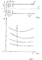
- the sketch according to FIG. 1 shows a typical structure of a beam system with a Triode grid arrangement with the electrodes cathode K, first grid G1 usually referred to as grid1, second grid with two electrodes G21 (grid 2/1) and G22 (grid 2/2), grid3 G3 with focus opening and sleeve as well as anode A.
- the ray axis of the undeflected line is entered as a dash-dotted line Electron beam.
- the course of the electron beam after the cross-over is divergent.
- the focusing effect of the pre-focusing lens means that after the cross-over strongly divergent beam is bundled again and passes through the sleeve of the electrode G3 with low divergence.
- the main lens HL is used for optimal focusing of the electron beam on the screen.
- the exact position of the real cross-over depends on the beam current (Intensity) of the electron beam and shifts due to the repulsion of the Electrons with each other with increasing beam current away from the cathode in Beam direction.
- the shift of the cross-over with increasing beam current has the consequence that the focusing effect of the pre-focusing lens decreases. This increases the divergence of the electron beam as the beam current increases in the sleeve of the electrode G3 (focus cylinder).
- This in turn will Cross section of the electron beam in the main lens enlarged, which is due to the spherical aberration of the main lens then at higher beam currents causes a stronger spot of a depicted point on the screen.
- the pre-focusing lens is dimensioned so that an optimal imaging quality is reached at high beam current, the one shown increases Point with small jet currents.
- the effect of the pre-focusing lens in Depending on the beam intensity (beam current) varies.
- Beam current is preferably supplied to the control electronics of the tube Brightness control signal or a signal derived therefrom. In this way it can be achieved that both at low and at high Optimal image quality is achieved.
- the focusing one The effect of the pre-focusing lens increases with increasing beam current. For Realization are listed below several advantageous alternatives.
- electrode voltages are used mentioned, which measured against a common reference potential (mass) where the voltage applied to cathode or grid1 is often at or is placed near ground.
- a positive voltage means a potential gradient and thus an acceleration field.
- the different variants have in common that the anode voltage is regarded as constant and z. B. is about 30 kV.
- the on Grid3 applied voltage is in practice dependent on the deflection signal varies to reflect the different beam paths in the deflection different areas of the screen when focusing the main lens too will take into account, however, in the following explanations, since for the Differentiation according to different jet currents is irrelevant, also as viewed unchanged, which is a consideration of the image of the undeflected Corresponds to the electron beam.
- the cathode control, the grid control and the cathode grid 1 push-pull control are essential for influencing the intensity of the electron beam.
- the grid 1 electrode G1 is at constant potential as the cathode control held and the voltage applied to the cathode, positive to G1 varies such that starting from an initial value at which no electron beam is generated, the cathode voltage for increasing beam intensity is reduced, for example from +100 V to + 50 V with a grid electrode connected to 0 V. G1.
- the cathode K is constant Potential, for example 0 V and at the grid electrode G1 is opposite the cathode negative voltage, for example from -100 V is varied after -50 V (from dark tube to maximum brightness).
- the focusing effect of the pre-focusing lens provides that on the grid electrode G22 to vary the applied voltage.
- this voltage depending the beam intensity (or an equivalent size as cathodes and / or grid 1 voltage, brightness control signal, etc.) can be the inventive Change the focusing effect of the pre-focusing lens can be controlled.
- the typically negative applied to the grid electrode G22 Voltage decreased with increasing beam current, for example from -150 V to -200 V.
- the change in voltage U22 at the grid electrode G22 thus runs in the same direction (i.e. the voltage decreases with increasing Beam current) like the cathode voltage and / or in the grid 1 voltage opposite direction.
- FIG. 2 schematically shows the course of line widths WL of an imaged one Point or a depicted line on the screen depending on the voltage U22 applied to the grid electrode G22.
- the curves show Minima, i.e. places with the smallest line width, at different voltage values of U22, the minima with increasing beam current Ik as parameters shift to lower voltage values of U22 and at the same time are more pronounced.
- FIG. 3 is an evaluation of such a family of curves according to FIG. 2 the dependency the voltage U22 to be selected for optimum image sharpness Beam current Ik plotted, with the tendency towards more negative voltage values for U22 is clearly expressed with increasing beam current Ik. If, as in the example of FIG. 2, the minima of the curves outlined there for small ones Jet currents are not particularly pronounced, the voltage swing of the course according to FIG. 3 can be reduced in such a way that for low jet currents not the optimal voltage values for U22 are selected, but for them small beam currents the optimum, that is, with respect to the curves in FIG. 2 that Minimum curve, is only approximated. In the voltage curve according to FIG. 3rd can, for example, the voltage rise towards small beam currents limited to the limit indicated by the dashed line become. A smaller voltage swing is advantageous for the dimensioning of the associated control signal generator.
- Another advantageous embodiment for influencing the focusing effect the pre-focusing lens provides, not only the one lying against the grid electrode G22 Voltage U22 to vary with the beam current, but also that at the Grid electrode G21 to change the applied voltage.
- This tension will usually used to set the so-called cut-off point by with fixed initial values for the cathode voltage and / or the grid 1 voltage the voltage at the electrode G21 is set so that just no point is shown on the screen.
- the change in the Grid electrode G21 applied voltage is used to influence the focusing effect the pre-focusing lens in such a way that with increasing Beam current the voltage applied to the grid electrode G21 starting from Your cut-off setting value is increased.
- the change in the grid electrode In this version, voltage applied to G21 runs in opposite directions to change the voltage at the grid electrode G22 and in opposite directions to the cathode voltage and / or the same as that applied to grid G1 Tension.
- the voltage swing when varying the grid voltage on lattice 21 it is again preferred that the voltage swing is smaller than the mean voltage between the grid electrodes G21 and G22 and / or is less than the voltage of the grid electrode G21 against the reference potential of the Blasting system.
- the voltage at the grid electrode G21 has a voltage swing of 750 for the brightness modulation range of the tube V to 800 V.
- the variation of the voltage at the grid electrode G21 also has an effect still distributing on the beam current characteristic by increasing it Voltage value has a more accelerating effect on the emitted electrons and thereby contributing to the increase itself through the course of your change of the jet current.
Landscapes
- Cathode-Ray Tubes And Fluorescent Screens For Display (AREA)
- Cold Cathode And The Manufacture (AREA)
Applications Claiming Priority (2)
| Application Number | Priority Date | Filing Date | Title |
|---|---|---|---|
| DE1997142028 DE19742028A1 (de) | 1997-09-24 | 1997-09-24 | Kathodenstrahlröhre |
| DE19742028 | 1997-09-24 |
Publications (2)
| Publication Number | Publication Date |
|---|---|
| EP0905739A2 true EP0905739A2 (fr) | 1999-03-31 |
| EP0905739A3 EP0905739A3 (fr) | 2003-03-26 |
Family
ID=7843397
Family Applications (1)
| Application Number | Title | Priority Date | Filing Date |
|---|---|---|---|
| EP98117321A Withdrawn EP0905739A3 (fr) | 1997-09-24 | 1998-09-12 | Tube à rayons cathodiques |
Country Status (2)
| Country | Link |
|---|---|
| EP (1) | EP0905739A3 (fr) |
| DE (1) | DE19742028A1 (fr) |
Cited By (3)
| Publication number | Priority date | Publication date | Assignee | Title |
|---|---|---|---|---|
| WO2001048786A1 (fr) * | 1999-12-24 | 2001-07-05 | Koninklijke Philips Electronics N.V. | Dispositif de visualisation couleur |
| WO2003034459A1 (fr) * | 2001-10-12 | 2003-04-24 | Koninklijke Philips Electronics N.V. | Tube cathodique |
| DE10153905A1 (de) * | 2001-11-02 | 2003-05-15 | Grundig Ag | Vorrichtung und Verfahren für das Erzeugen einer Fokuselektrodenspannung für eine Bildröhre |
Family Cites Families (4)
| Publication number | Priority date | Publication date | Assignee | Title |
|---|---|---|---|---|
| US4334170A (en) * | 1979-09-28 | 1982-06-08 | Zenith Radio Corporation | Means and method for providing optimum resolution of T.V. cathode ray tube electron guns |
| US4481445A (en) * | 1982-06-01 | 1984-11-06 | Zenith Electronics Corporation | Electron gun for projection television cathode ray tubes |
| US4591760A (en) * | 1983-03-25 | 1986-05-27 | Matsushita Electronics Corporation | Cathode ray tube apparatus |
| KR960016260B1 (ko) * | 1993-09-04 | 1996-12-07 | 엘지전자 주식회사 | 인라인형 칼라 음극선관용 전자총의 전압 인가 방법 및 전극 구조 |
-
1997
- 1997-09-24 DE DE1997142028 patent/DE19742028A1/de not_active Withdrawn
-
1998
- 1998-09-12 EP EP98117321A patent/EP0905739A3/fr not_active Withdrawn
Cited By (4)
| Publication number | Priority date | Publication date | Assignee | Title |
|---|---|---|---|---|
| WO2001048786A1 (fr) * | 1999-12-24 | 2001-07-05 | Koninklijke Philips Electronics N.V. | Dispositif de visualisation couleur |
| WO2003034459A1 (fr) * | 2001-10-12 | 2003-04-24 | Koninklijke Philips Electronics N.V. | Tube cathodique |
| US6888300B2 (en) | 2001-10-12 | 2005-05-03 | Koninklijke Philips Electronics N.V. | Cathode ray tube |
| DE10153905A1 (de) * | 2001-11-02 | 2003-05-15 | Grundig Ag | Vorrichtung und Verfahren für das Erzeugen einer Fokuselektrodenspannung für eine Bildröhre |
Also Published As
| Publication number | Publication date |
|---|---|
| DE19742028A1 (de) | 1999-03-25 |
| EP0905739A3 (fr) | 2003-03-26 |
Similar Documents
| Publication | Publication Date | Title |
|---|---|---|
| DE68916283T2 (de) | Elektronenkanone für Farbbildröhre. | |
| DE3614700C2 (fr) | ||
| DE3839389C2 (fr) | ||
| CH364046A (de) | Elektronenlinsenanordnung in einem Elektronenstrahlgerät | |
| DE68928732T2 (de) | Elektronenkanonenvorrichtung für Kathodenstrahlröhre | |
| DE2459091C3 (de) | Strahlerzeugungssystem einer Kathodenstrahlröhre | |
| DD273718A5 (de) | Farbbil-kathodenstrahlroehre | |
| DE3882408T2 (de) | Elektronenkanone für eine Farbbildröhre. | |
| DE4037029C2 (de) | Elektronenkanone für eine Farbkathodenstrahlröhre | |
| DE69013183T2 (de) | Farbbildröhrensystem mit reduziertem Fleckwachstum. | |
| DE69605053T2 (de) | Kanonenlinse zur Partikelstrahlerzeugung | |
| DE3142777C2 (de) | Elektronenkanone | |
| DE2914838C2 (de) | Elektronenstrahlerzeugungssystem | |
| DE3854466T2 (de) | Elektronenkanonen für Kathodenstrahl-Röhren. | |
| EP0905739A2 (fr) | Tube à rayons cathodiques | |
| DE2114310C3 (de) | Kathodenstrahl-Bildröhre | |
| DE68906441T2 (de) | Elektronenkanone für Farbbildröhre. | |
| DE3022921A1 (de) | Fernsehaufnahmeroehre | |
| DE2830696C2 (de) | Bildaufnahmevorrichtung | |
| DE3216039C2 (de) | Elektronenstrahl-Erzeugungssystem einer Kathodenstrahlröhre | |
| DE4431335B4 (de) | Elektronenkanone für eine Farbbildröhre | |
| DE69503343T2 (de) | Anzeigevorrichtung und kathodenstrahlröhre | |
| DE2825900A1 (de) | Elektronenstrahlroehre-elektronenstrahlerzeuger | |
| DE69532441T2 (de) | Farbkathodenstrahlröhre mit einer in-line-elektronenkanone | |
| DE755242C (de) | Schaltungsanordnung zur Ablenkung des Strahls in Kathodenstrahl-roehren, bei denen die Mittelsenkrechte auf dem Schirm und die Roehrenachse nicht zusammenfallen |
Legal Events
| Date | Code | Title | Description |
|---|---|---|---|
| PUAI | Public reference made under article 153(3) epc to a published international application that has entered the european phase |
Free format text: ORIGINAL CODE: 0009012 |
|
| AK | Designated contracting states |
Kind code of ref document: A2 Designated state(s): AT BE CH CY DE DK ES FI FR GB GR IE IT LI LU MC NL PT SE |
|
| AX | Request for extension of the european patent |
Free format text: AL;LT;LV;MK;RO;SI |
|
| RAP1 | Party data changed (applicant data changed or rights of an application transferred) |
Owner name: THALES ELECTRON DEVICES GMBH |
|
| RAP1 | Party data changed (applicant data changed or rights of an application transferred) |
Owner name: SAMTEL ELECTRON DEVICES GMBH |
|
| PUAL | Search report despatched |
Free format text: ORIGINAL CODE: 0009013 |
|
| AK | Designated contracting states |
Kind code of ref document: A3 Designated state(s): AT BE CH CY DE DK ES FI FR GB GR IE IT LI LU MC NL PT SE Designated state(s): AT BE CH CY DE DK ES FI FR GB GR IE IT LI LU MC NL PT SE |
|
| AX | Request for extension of the european patent |
Extension state: AL LT LV MK RO SI |
|
| RIC1 | Information provided on ipc code assigned before grant |
Ipc: 7H 01J 29/48 B Ipc: 7H 01J 29/46 A |
|
| AKX | Designation fees paid | ||
| REG | Reference to a national code |
Ref country code: DE Ref legal event code: 8566 |
|
| STAA | Information on the status of an ep patent application or granted ep patent |
Free format text: STATUS: THE APPLICATION IS DEEMED TO BE WITHDRAWN |
|
| 18D | Application deemed to be withdrawn |
Effective date: 20030927 |