EP0905849A1 - Dispositif de commutation pour gérer un réseau multiphase comportant un nombre de charges - Google Patents
Dispositif de commutation pour gérer un réseau multiphase comportant un nombre de charges Download PDFInfo
- Publication number
- EP0905849A1 EP0905849A1 EP98203095A EP98203095A EP0905849A1 EP 0905849 A1 EP0905849 A1 EP 0905849A1 EP 98203095 A EP98203095 A EP 98203095A EP 98203095 A EP98203095 A EP 98203095A EP 0905849 A1 EP0905849 A1 EP 0905849A1
- Authority
- EP
- European Patent Office
- Prior art keywords
- phase
- current
- control unit
- conductor
- switching device
- Prior art date
- Legal status (The legal status is an assumption and is not a legal conclusion. Google has not performed a legal analysis and makes no representation as to the accuracy of the status listed.)
- Granted
Links
- 239000004020 conductor Substances 0.000 claims abstract description 60
- 238000001514 detection method Methods 0.000 claims abstract description 29
- 230000007935 neutral effect Effects 0.000 claims abstract description 23
- 230000001419 dependent effect Effects 0.000 claims abstract description 5
- 239000013598 vector Substances 0.000 claims description 24
- 238000012544 monitoring process Methods 0.000 claims description 6
- 230000001934 delay Effects 0.000 claims 1
- 238000009434 installation Methods 0.000 description 9
- 238000010586 diagram Methods 0.000 description 5
- 238000011068 loading method Methods 0.000 description 2
- 230000003071 parasitic effect Effects 0.000 description 2
- 230000035945 sensitivity Effects 0.000 description 2
- 230000002950 deficient Effects 0.000 description 1
- 238000005259 measurement Methods 0.000 description 1
- 230000003014 reinforcing effect Effects 0.000 description 1
- 238000011144 upstream manufacturing Methods 0.000 description 1
- 238000004804 winding Methods 0.000 description 1
Images


Classifications
-
- H—ELECTRICITY
- H02—GENERATION; CONVERSION OR DISTRIBUTION OF ELECTRIC POWER
- H02H—EMERGENCY PROTECTIVE CIRCUIT ARRANGEMENTS
- H02H3/00—Emergency protective circuit arrangements for automatic disconnection directly responsive to an undesired change from normal electric working condition with or without subsequent reconnection ; integrated protection
- H02H3/26—Emergency protective circuit arrangements for automatic disconnection directly responsive to an undesired change from normal electric working condition with or without subsequent reconnection ; integrated protection responsive to difference between voltages or between currents; responsive to phase angle between voltages or between currents
- H02H3/32—Emergency protective circuit arrangements for automatic disconnection directly responsive to an undesired change from normal electric working condition with or without subsequent reconnection ; integrated protection responsive to difference between voltages or between currents; responsive to phase angle between voltages or between currents involving comparison of the voltage or current values at corresponding points in different conductors of a single system, e.g. of currents in go and return conductors
- H02H3/34—Emergency protective circuit arrangements for automatic disconnection directly responsive to an undesired change from normal electric working condition with or without subsequent reconnection ; integrated protection responsive to difference between voltages or between currents; responsive to phase angle between voltages or between currents involving comparison of the voltage or current values at corresponding points in different conductors of a single system, e.g. of currents in go and return conductors of a three-phase system
- H02H3/347—Emergency protective circuit arrangements for automatic disconnection directly responsive to an undesired change from normal electric working condition with or without subsequent reconnection ; integrated protection responsive to difference between voltages or between currents; responsive to phase angle between voltages or between currents involving comparison of the voltage or current values at corresponding points in different conductors of a single system, e.g. of currents in go and return conductors of a three-phase system using summation current transformers
-
- H—ELECTRICITY
- H05—ELECTRIC TECHNIQUES NOT OTHERWISE PROVIDED FOR
- H05B—ELECTRIC HEATING; ELECTRIC LIGHT SOURCES NOT OTHERWISE PROVIDED FOR; CIRCUIT ARRANGEMENTS FOR ELECTRIC LIGHT SOURCES, IN GENERAL
- H05B47/00—Circuit arrangements for operating light sources in general, i.e. where the type of light source is not relevant
- H05B47/20—Responsive to malfunctions or to light source life; for protection
- H05B47/25—Circuit arrangements for protecting against overcurrent
-
- H—ELECTRICITY
- H05—ELECTRIC TECHNIQUES NOT OTHERWISE PROVIDED FOR
- H05B—ELECTRIC HEATING; ELECTRIC LIGHT SOURCES NOT OTHERWISE PROVIDED FOR; CIRCUIT ARRANGEMENTS FOR ELECTRIC LIGHT SOURCES, IN GENERAL
- H05B47/00—Circuit arrangements for operating light sources in general, i.e. where the type of light source is not relevant
- H05B47/20—Responsive to malfunctions or to light source life; for protection
- H05B47/26—Circuit arrangements for protecting against earth faults
-
- H—ELECTRICITY
- H02—GENERATION; CONVERSION OR DISTRIBUTION OF ELECTRIC POWER
- H02H—EMERGENCY PROTECTIVE CIRCUIT ARRANGEMENTS
- H02H3/00—Emergency protective circuit arrangements for automatic disconnection directly responsive to an undesired change from normal electric working condition with or without subsequent reconnection ; integrated protection
- H02H3/08—Emergency protective circuit arrangements for automatic disconnection directly responsive to an undesired change from normal electric working condition with or without subsequent reconnection ; integrated protection responsive to excess current
- H02H3/083—Emergency protective circuit arrangements for automatic disconnection directly responsive to an undesired change from normal electric working condition with or without subsequent reconnection ; integrated protection responsive to excess current for three-phase systems
-
- H—ELECTRICITY
- H02—GENERATION; CONVERSION OR DISTRIBUTION OF ELECTRIC POWER
- H02H—EMERGENCY PROTECTIVE CIRCUIT ARRANGEMENTS
- H02H3/00—Emergency protective circuit arrangements for automatic disconnection directly responsive to an undesired change from normal electric working condition with or without subsequent reconnection ; integrated protection
- H02H3/08—Emergency protective circuit arrangements for automatic disconnection directly responsive to an undesired change from normal electric working condition with or without subsequent reconnection ; integrated protection responsive to excess current
- H02H3/10—Emergency protective circuit arrangements for automatic disconnection directly responsive to an undesired change from normal electric working condition with or without subsequent reconnection ; integrated protection responsive to excess current additionally responsive to some other abnormal electrical conditions
- H02H3/105—Emergency protective circuit arrangements for automatic disconnection directly responsive to an undesired change from normal electric working condition with or without subsequent reconnection ; integrated protection responsive to excess current additionally responsive to some other abnormal electrical conditions responsive to excess current and fault current to earth
Definitions
- the invention relates to a switching device for managing a multi-phase alternating-voltage network having a phase conductor leading to a number of load units for each phase and a neutral conductor which is common to load units connected to various phase conductors, comprising, for each phase conductor a current detector for supplying an associated detection signal which is dependent on the current through the phase conductor and a switch which is connected in series with the phase conductor and the load units connected thereto and which is opened if the magnitude of the associated detection signal exceeds a first reference value.
- a switching device of this sort is known from Dutch Patent Application 8902169.
- the object of the known device is to provide a protection against the occurrence of a short circuit between a phase conductor and the neutral conductor at a relatively large distance from the switching device.
- the known device comprises, for each phase conductor, a magnetic protection having a current transformer which feeds an associated current measuring relay. If a current delivered to the relay by the current transformer exceeds a predetermined value, the relay is energized and feeds an associated time relay. After the expiry of a delay time of the time relay, the latter controls a phase switching relay having a first phase switching member in series with the respective phase conductor to switch off the phase conductor.
- the delay time of the time relay is chosen in accordance with a maximum permissible contact time. In practice, however, a time shorter than one second has not proved possible. Furthermore, the short-circuit current increases as the short circuit is closer to the switching device. For this reason, such a magnetic protection is combined with a standard short-circuit protection having a thermal action for high currents, a second phase switching member for each phase being in series with the associated first phase switching device in such a way that, at relatively high currents, the short-circuit protection switches off the respective phase instead of the magnetic protection and does this earlier than the latter would do.
- the known switching device has the drawback that only a limited monitoring, namely upward transgression, of the various currents through the phase conductors is possible. A very dangerous situation in which a load unit or another electrical member is under voltage as a consequence of an earth-leakage between a phase conductor or the neutral conductor and earth is not monitored.
- Another drawback of the known device is that the monitoring takes place by means of electromechanical means, in particular relays, which make the adjustment of current reference levels and delay times difficult and inaccurate, the adjustments are difficult to match to changed circumstances, such as different loadings of the phase conductors, and the device is relatively sensitive to interference.
- the object of the invention is to eliminate the drawbacks of the known device.
- the switching device of the type mentioned in the preamble is characterized, according to the invention, in that a current detector is added to the neutral conductor in order to supply an associated detection signal which is dependent on the current through the neutral conductor, all the detection signals are supplied to a control unit, the control unit adds the detection signals vectorially in order to obtain a first vector sum and, if the magnitude of the first vector sum exceeds a second reference value, the control unit opens a switch, the associated phase of which essentially corresponds to the phase of the first vector sum.
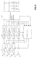
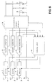
- the switching device according to the invention shown in Figure 1 is intended for managing a three-phase alternating-voltage network and comprises an associated phase conductor 1, 2, 3 for each phase L1, L2, L3 and a neutral conductor 4 for a neutral phase N, all the conductors 1, 2, 3, 4 leading to a number of load units 5.
- the load units are, in particular, lighting fittings of a public lighting installation for which the neutral conductor 5 is common and light fittings arranged at consecutive intervals are connected in turn to the various phase conductors 1, 2, 3.
- the switching device comprises, for each phase L1, L2, L3 and for the neutral phase N, a current detector 6 and, in series with each phase conductor 1, 2, 3, a switch 7.
- Each current detector 6 detects the current which passes through the associated phase conductor 1, 2, 3 and delivers a detection signal associated therewith to a control unit 8.
- the current detectors 6 each comprise, in particular, a current transformer followed by a current/voltage converter for delivering the detection signal to the control unit 8.
- the current/voltage converter may be fitted in the control unit 8 itself.
- the control unit 8 is a digital processing unit which digitizes the received detection signals, compares them individually and in combination with one or more reference values and, depending on the comparison results, drives one or more switches 7 into the open state.
- a digital processing unit preferably comprises means for the external adjustment of the reference values.
- the control unit 8 is suitable for monitoring the occurrence of a short circuit between one of the phase conductors 1, 2, 3 and the neutral conductor 4. In this connection, if the magnitude of a detection signal associated with a phase conductor 1, 2, 3 exceeds a predetermined reference value, the control unit opens the switch 7 associated with the phase conductor 1, 2, 3.
- the reference value at which this happens is, in particular, a value which does not occur during normal operation of the lighting installation, but does occur if a short circuit occurs in or at the most distant light fitting.
- control unit 8 In the event of an excessively high (short-circuit) current through a switch 7, the control unit 8 energizes the switch 7 with a delay so that a standard short-circuit protection connected upstream can take over any switching-off of the associated phase.
- control unit 8 comprises a digital processing unit
- the control unit 8 is suitable for monitoring the occurrence of deviations from the normal operation of the installation, in particular by monitoring the upward or downward transgression of other reference values by the detection signals, such as for detecting the failure of one or more lamps, in which case the magnitude of the detection circuit of the associated phase conductor 1, 2, 3 will be lower than a normal value.
- the vectorial sum S of the associated vectors L1 , L2 , L3 , N has to be zero (zero vector) in a satisfactorily operating installation.
- the control unit 8 calculates said vectorial sum S and monitors whether it is not equal to zero. If the vector sum S is not equal to zero, this means that a portion of a current through a phase conductor 1, 2, 3 does not flow via the neutral conductor 4, but leaks away via another path, in particular earth.
- the vectorial sum mentioned consequently represents a vector E for the leakage current.
- the leakage-current vector E has the same direction as the vector of one of the currents, in Figure 4 L3 , through the phase conductors 1, 2, 3 which, in addition to a current, conducts the leakage current E to load units 5. If the control unit 8 detects that the magnitude of the leakage current E exceeds a predetermined reference value, for example 300 mA, the control unit 8 drives the switch 7 which is associated with the phase, in Figure 4 phase L3, having the same vectorial angle as the leakage-current vector, into the open state.
- a predetermined reference value for example 300 mA
- the switching device in accordance with the embodiment according to the invention shown in Figure 5 comprises, in addition, a differential current detector 9 which comprises, in particular, a current transformer having a common core for each of the conductors 1, 2, 3, 4 and a single detection winding followed by a current/voltage converter for delivering a further detection signal to the control unit 8.
- the further detection signal represents the abovementioned vectorial sum S of the currents L1 , L2 , L3 , N through the conductors 1, 2, 3, 4 and, therefore, also the said leakage-current vector E .
- the detection signal it delivers is less subject to parasitic effects, as a result of which the control unit 8 can compare the leakage-current vector determined therewith with a lower reference magnitude, for example 30 mA, than in the embodiment of Figure 1.
Landscapes
- Engineering & Computer Science (AREA)
- Power Engineering (AREA)
- Emergency Protection Circuit Devices (AREA)
- Circuit Arrangement For Electric Light Sources In General (AREA)
Applications Claiming Priority (2)
| Application Number | Priority Date | Filing Date | Title |
|---|---|---|---|
| NL1007122 | 1997-09-25 | ||
| NL1007122A NL1007122C2 (nl) | 1997-09-25 | 1997-09-25 | Schakelinrichting voor het beheren van een meerfasig wisselspanningsnet met een aantal gebruikseenheden. |
Publications (2)
| Publication Number | Publication Date |
|---|---|
| EP0905849A1 true EP0905849A1 (fr) | 1999-03-31 |
| EP0905849B1 EP0905849B1 (fr) | 2005-02-09 |
Family
ID=19765736
Family Applications (1)
| Application Number | Title | Priority Date | Filing Date |
|---|---|---|---|
| EP98203095A Expired - Lifetime EP0905849B1 (fr) | 1997-09-25 | 1998-09-16 | Dispositif de commutation pour gérer un réseau multiphase comportant un nombre de charges |
Country Status (3)
| Country | Link |
|---|---|
| EP (1) | EP0905849B1 (fr) |
| DE (1) | DE69828930T2 (fr) |
| NL (1) | NL1007122C2 (fr) |
Cited By (6)
| Publication number | Priority date | Publication date | Assignee | Title |
|---|---|---|---|---|
| WO2003026091A1 (fr) * | 2001-09-14 | 2003-03-27 | Hydro-Aire, Inc. | Detecteur de defauts de courant, interrupteur de circuit et assemblage en boitier associe |
| US6583975B2 (en) | 2001-02-01 | 2003-06-24 | Hydro-Aire, Inc. | Aircraft applicable ground fault circuit interrupter |
| WO2006056510A1 (fr) * | 2004-11-24 | 2006-06-01 | Siemens Aktiengesellschaft | Circuit de commande et de controle d'une pluralite de lampes de signalisation |
| US7362551B2 (en) | 2001-02-01 | 2008-04-22 | Hydro-Aire, Inc. | Aircraft applicable circuit imbalance detection and circuit interrupter and packaging thereof |
| EP2015419A3 (fr) * | 2007-07-13 | 2012-04-18 | Siemens Aktiengesellschaft | Procédé d'attribution d'un courant différentiel à l'une des trois conduites de phases d'un système triphasé et circuit de protection du courant différentiel |
| EP3654478A1 (fr) * | 2018-11-16 | 2020-05-20 | Eaton Intelligent Power Limited | Installation d'interrupteur de circuit et procédé associé |
Citations (2)
| Publication number | Priority date | Publication date | Assignee | Title |
|---|---|---|---|---|
| EP0037751A1 (fr) * | 1980-03-31 | 1981-10-14 | Merlin Gerin | Déclencheur statique perfectionné pour disjoncteur électrique |
| EP0674376A2 (fr) * | 1994-03-25 | 1995-09-27 | Eaton Corporation | Module déclencheur contre les surintensités avec protection de neutre ajustable separément |
-
1997
- 1997-09-25 NL NL1007122A patent/NL1007122C2/nl not_active IP Right Cessation
-
1998
- 1998-09-16 DE DE69828930T patent/DE69828930T2/de not_active Expired - Fee Related
- 1998-09-16 EP EP98203095A patent/EP0905849B1/fr not_active Expired - Lifetime
Patent Citations (2)
| Publication number | Priority date | Publication date | Assignee | Title |
|---|---|---|---|---|
| EP0037751A1 (fr) * | 1980-03-31 | 1981-10-14 | Merlin Gerin | Déclencheur statique perfectionné pour disjoncteur électrique |
| EP0674376A2 (fr) * | 1994-03-25 | 1995-09-27 | Eaton Corporation | Module déclencheur contre les surintensités avec protection de neutre ajustable separément |
Cited By (21)
| Publication number | Priority date | Publication date | Assignee | Title |
|---|---|---|---|---|
| US7417835B2 (en) | 2001-02-01 | 2008-08-26 | Hydro-Aire, Inc. | Aircraft applicable circuit imbalance detection and circuit interrupter and packaging thereof |
| US7630182B2 (en) | 2001-02-01 | 2009-12-08 | Hydro-Aire, Inc. | Aircraft applicable current imbalance detection and circuit interrupter and packaging thereof |
| US6618229B2 (en) | 2001-02-01 | 2003-09-09 | Hydro-Aire, Inc. | Aircraft applicable current imbalance detection and circuit interrupter and packaging thereof |
| US7016171B2 (en) | 2001-02-01 | 2006-03-21 | Hydro-Aire, Inc. | Current fault detector and circuit interrupter and packaging thereof |
| US7688558B2 (en) | 2001-02-01 | 2010-03-30 | Hydro-Aire, Inc. | Aircraft applicable circuit imbalance detection and circuit interrupter and packaging thereof |
| US7064941B2 (en) | 2001-02-01 | 2006-06-20 | Hydro-Aire, Inc. | Aircraft applicable current imbalance detection and circuit interrupter and packaging thereof |
| US7248451B2 (en) | 2001-02-01 | 2007-07-24 | Hydro-Aire, Inc. | Current fault detector and circuit interrupter and packaging thereof |
| US7362551B2 (en) | 2001-02-01 | 2008-04-22 | Hydro-Aire, Inc. | Aircraft applicable circuit imbalance detection and circuit interrupter and packaging thereof |
| US7375937B2 (en) | 2001-02-01 | 2008-05-20 | Hydro-Aire, Inc. | Current fault detector and circuit interrupter and packaging thereof |
| US7417836B2 (en) | 2001-02-01 | 2008-08-26 | Hydro-Aire, Inc. | Aircraft applicable circuit imbalance detection and circuit interrupter and packaging thereof |
| US6583975B2 (en) | 2001-02-01 | 2003-06-24 | Hydro-Aire, Inc. | Aircraft applicable ground fault circuit interrupter |
| US7672099B2 (en) | 2001-02-01 | 2010-03-02 | Hydro-Aire, Inc. | Current fault detector and circuit interrupter and packaging thereof |
| US7667935B2 (en) | 2001-02-01 | 2010-02-23 | Hydro-Aire, Inc. | Aircraft applicable circuit imbalance detection and circuit interrupter and packaging thereof |
| WO2003026091A1 (fr) * | 2001-09-14 | 2003-03-27 | Hydro-Aire, Inc. | Detecteur de defauts de courant, interrupteur de circuit et assemblage en boitier associe |
| CN100568656C (zh) * | 2001-09-14 | 2009-12-09 | 海卓-艾尔公司 | 电流故障检测器和电路断流器及其组件 |
| WO2006056510A1 (fr) * | 2004-11-24 | 2006-06-01 | Siemens Aktiengesellschaft | Circuit de commande et de controle d'une pluralite de lampes de signalisation |
| EP2015419A3 (fr) * | 2007-07-13 | 2012-04-18 | Siemens Aktiengesellschaft | Procédé d'attribution d'un courant différentiel à l'une des trois conduites de phases d'un système triphasé et circuit de protection du courant différentiel |
| EP3654478A1 (fr) * | 2018-11-16 | 2020-05-20 | Eaton Intelligent Power Limited | Installation d'interrupteur de circuit et procédé associé |
| CN111198337A (zh) * | 2018-11-16 | 2020-05-26 | 伊顿智能动力有限公司 | 电路断流器装置及相关联的方法 |
| US10992126B2 (en) | 2018-11-16 | 2021-04-27 | Eaton Intelligent Power Limited | Circuit interrupter installation and associated method |
| CN111198337B (zh) * | 2018-11-16 | 2024-05-17 | 伊顿智能动力有限公司 | 电路断流器装置及相关联的方法 |
Also Published As
| Publication number | Publication date |
|---|---|
| DE69828930D1 (de) | 2005-03-17 |
| NL1007122C2 (nl) | 1999-03-26 |
| EP0905849B1 (fr) | 2005-02-09 |
| DE69828930T2 (de) | 2006-01-19 |
Similar Documents
| Publication | Publication Date | Title |
|---|---|---|
| US5768079A (en) | Adaptive ground and phase fault detection for a power distribution system | |
| JP5466302B2 (ja) | 多相地絡障害回路遮断器のためのシステムおよび方法 | |
| US6573726B1 (en) | Sensitive ground fault detection system for use in compensated electric power distribution networks | |
| US8837097B2 (en) | Protection, monitoring or indication apparatus for a direct current electrical generating apparatus or a plurality of strings | |
| US11852692B1 (en) | Electric distribution line ground fault prevention systems using dual parameter monitoring with high sensitivity relay devices | |
| KR20090032532A (ko) | 역 조류에 의한 지락과전류 계전기 오동작 방지 제어방법 | |
| KR100920946B1 (ko) | 부하 기기의 영향을 고려한 배전 선로의 고장 검출 및위치를 판단하는 장치 및 방법 | |
| CA1320561C (fr) | Controle de la deperdition de potentiel dans les telerelais | |
| EP0905849B1 (fr) | Dispositif de commutation pour gérer un réseau multiphase comportant un nombre de charges | |
| US20110178649A1 (en) | Method for preventing electric shock by contact with connected-to-ground electric appliances and installations, and apparatus therefor | |
| EP0999633B1 (fr) | Protection contre les courants de défaut à la terre dans un réseau de distribution électrique | |
| US4796147A (en) | Method for detecting voltage losses in a low voltage distribution system | |
| JPH08205377A (ja) | き電設備の保護装置 | |
| KR100694279B1 (ko) | 전기철도용 직류 급전계통에서의 지락보호계전방법 | |
| KR101030193B1 (ko) | 중성선 대체기능이 구비된 분배전반 및 그 분배전반의 중성선 대체방법 | |
| US6737869B2 (en) | Fault locator and selectivity sensor | |
| JP2860740B2 (ja) | 系統連系保護検出装置 | |
| US20260112890A1 (en) | Electric Distribution Line Ground Fault Prevention Systems Using Dual Parameter High Sensitivity Relay Device, Monitoring Small Current Reduction with Small Increase in Negative Sequence Current | |
| RU2788519C1 (ru) | Способ отключения поврежденного присоединения с однофазным замыканием на землю в сетях с изолированной нейтралью | |
| US20240195163A1 (en) | Electric Distribution Line Ground Fault Prevention Systems Using Dual Parameter High Sensitivity Relay Device Monitoring With Blown Fuse Protection In A Single Phase Tap Line | |
| KR20250039096A (ko) | 선택적 지락 검출 시스템 | |
| KR20260067832A (ko) | 계전기의 제어 회로, 계전기, 계전기의 제어 방법 및 배전 시스템 | |
| JP2558585B2 (ja) | 系統連系保護検出装置 | |
| JPH0620342B2 (ja) | 断線検出継電器 | |
| EP0120209B1 (fr) | Méthode pour détecter la fréquence d'une alimentation |
Legal Events
| Date | Code | Title | Description |
|---|---|---|---|
| PUAI | Public reference made under article 153(3) epc to a published international application that has entered the european phase |
Free format text: ORIGINAL CODE: 0009012 |
|
| AK | Designated contracting states |
Kind code of ref document: A1 Designated state(s): BE DE GB LU NL |
|
| AX | Request for extension of the european patent |
Free format text: AL;LT;LV;MK;RO;SI |
|
| 17P | Request for examination filed |
Effective date: 19990923 |
|
| AKX | Designation fees paid |
Free format text: BE DE GB LU NL |
|
| 17Q | First examination report despatched |
Effective date: 20040617 |
|
| GRAP | Despatch of communication of intention to grant a patent |
Free format text: ORIGINAL CODE: EPIDOSNIGR1 |
|
| GRAS | Grant fee paid |
Free format text: ORIGINAL CODE: EPIDOSNIGR3 |
|
| GRAA | (expected) grant |
Free format text: ORIGINAL CODE: 0009210 |
|
| AK | Designated contracting states |
Kind code of ref document: B1 Designated state(s): BE DE GB LU NL |
|
| REG | Reference to a national code |
Ref country code: GB Ref legal event code: FG4D |
|
| REF | Corresponds to: |
Ref document number: 69828930 Country of ref document: DE Date of ref document: 20050317 Kind code of ref document: P |
|
| PLBE | No opposition filed within time limit |
Free format text: ORIGINAL CODE: 0009261 |
|
| STAA | Information on the status of an ep patent application or granted ep patent |
Free format text: STATUS: NO OPPOSITION FILED WITHIN TIME LIMIT |
|
| 26N | No opposition filed |
Effective date: 20051110 |
|
| PGFP | Annual fee paid to national office [announced via postgrant information from national office to epo] |
Ref country code: NL Payment date: 20080924 Year of fee payment: 11 |
|
| PGFP | Annual fee paid to national office [announced via postgrant information from national office to epo] |
Ref country code: GB Payment date: 20080929 Year of fee payment: 11 |
|
| PGFP | Annual fee paid to national office [announced via postgrant information from national office to epo] |
Ref country code: LU Payment date: 20081006 Year of fee payment: 11 Ref country code: DE Payment date: 20081031 Year of fee payment: 11 |
|
| PGFP | Annual fee paid to national office [announced via postgrant information from national office to epo] |
Ref country code: BE Payment date: 20081009 Year of fee payment: 11 |
|
| BERE | Be: lapsed |
Owner name: *MONTAD ELEKTROTECHNISCH ADVIESBUREAU B.V. Effective date: 20090930 Owner name: *ODINK & KOENDERINK B.V. Effective date: 20090930 |
|
| REG | Reference to a national code |
Ref country code: NL Ref legal event code: V1 Effective date: 20100401 |
|
| GBPC | Gb: european patent ceased through non-payment of renewal fee |
Effective date: 20090916 |
|
| PG25 | Lapsed in a contracting state [announced via postgrant information from national office to epo] |
Ref country code: NL Free format text: LAPSE BECAUSE OF NON-PAYMENT OF DUE FEES Effective date: 20100401 Ref country code: DE Free format text: LAPSE BECAUSE OF NON-PAYMENT OF DUE FEES Effective date: 20100401 |
|
| PG25 | Lapsed in a contracting state [announced via postgrant information from national office to epo] |
Ref country code: BE Free format text: LAPSE BECAUSE OF NON-PAYMENT OF DUE FEES Effective date: 20090930 |
|
| PG25 | Lapsed in a contracting state [announced via postgrant information from national office to epo] |
Ref country code: GB Free format text: LAPSE BECAUSE OF NON-PAYMENT OF DUE FEES Effective date: 20090916 |
|
| PG25 | Lapsed in a contracting state [announced via postgrant information from national office to epo] |
Ref country code: LU Free format text: LAPSE BECAUSE OF NON-PAYMENT OF DUE FEES Effective date: 20090916 |