EP0907171A1 - Vorrichtung zur Identifizierung eines Aufzeichnungsmediums - Google Patents
Vorrichtung zur Identifizierung eines Aufzeichnungsmediums Download PDFInfo
- Publication number
- EP0907171A1 EP0907171A1 EP98307898A EP98307898A EP0907171A1 EP 0907171 A1 EP0907171 A1 EP 0907171A1 EP 98307898 A EP98307898 A EP 98307898A EP 98307898 A EP98307898 A EP 98307898A EP 0907171 A1 EP0907171 A1 EP 0907171A1
- Authority
- EP
- European Patent Office
- Prior art keywords
- package
- detecting
- spindle
- disk
- arm
- Prior art date
- Legal status (The legal status is an assumption and is not a legal conclusion. Google has not performed a legal analysis and makes no representation as to the accuracy of the status listed.)
- Withdrawn
Links
- 238000003780 insertion Methods 0.000 claims abstract description 27
- 230000037431 insertion Effects 0.000 claims abstract description 27
- 238000013459 approach Methods 0.000 claims description 6
- 230000000452 restraining effect Effects 0.000 claims 2
- 238000003825 pressing Methods 0.000 description 13
- 230000003287 optical effect Effects 0.000 description 4
- 238000005452 bending Methods 0.000 description 3
- 230000007423 decrease Effects 0.000 description 3
- 230000000717 retained effect Effects 0.000 description 3
- 229920003002 synthetic resin Polymers 0.000 description 3
- 239000000057 synthetic resin Substances 0.000 description 3
- 230000003247 decreasing effect Effects 0.000 description 2
- 230000000994 depressogenic effect Effects 0.000 description 2
- 238000001514 detection method Methods 0.000 description 2
- 239000002184 metal Substances 0.000 description 2
- 238000000034 method Methods 0.000 description 2
- 230000000881 depressing effect Effects 0.000 description 1
- 230000006870 function Effects 0.000 description 1
- 238000001746 injection moulding Methods 0.000 description 1
- 230000009191 jumping Effects 0.000 description 1
- 238000004080 punching Methods 0.000 description 1
- 238000010186 staining Methods 0.000 description 1
Images






Classifications
-
- G—PHYSICS
- G11—INFORMATION STORAGE
- G11B—INFORMATION STORAGE BASED ON RELATIVE MOVEMENT BETWEEN RECORD CARRIER AND TRANSDUCER
- G11B23/00—Record carriers not specific to the method of recording or reproducing; Accessories, e.g. containers, specially adapted for co-operation with the recording or reproducing apparatus ; Intermediate mediums; Apparatus or processes specially adapted for their manufacture
- G11B23/30—Record carriers not specific to the method of recording or reproducing; Accessories, e.g. containers, specially adapted for co-operation with the recording or reproducing apparatus ; Intermediate mediums; Apparatus or processes specially adapted for their manufacture with provision for auxiliary signals
-
- G—PHYSICS
- G11—INFORMATION STORAGE
- G11B—INFORMATION STORAGE BASED ON RELATIVE MOVEMENT BETWEEN RECORD CARRIER AND TRANSDUCER
- G11B17/00—Guiding record carriers not specifically of filamentary or web form, or of supports therefor
- G11B17/22—Guiding record carriers not specifically of filamentary or web form, or of supports therefor from random access magazine of disc records
- G11B17/30—Guiding record carriers not specifically of filamentary or web form, or of supports therefor from random access magazine of disc records wherein the playing unit is moved according to the location of the selected record
Definitions
- the present invention relates to a recording medium identifying device in which a package containing one disk or a plurality of disks such as CD, CD-ROM, DVD, PD, etc., or a package containing a built-in recording means other than the disk, is mounted to the body of the device.
- disk media of pit-modulation system are CD (Compact Disk), CD-ROM (CD-Read Only Memory),- and CD-R (CD-Rewritable) which allows only one time of recording.
- a phase-modulation type recordable /reproduceable medium is a PD (Power Disk)
- recordable /reproduceable media of photo electromagnetic system are MO (Magneto-Optical Memory), and HS (Hyper Storage).
- large-capacity disks for audio system, video system, and computer data are DVD-ROM (Digital Versatile Disk) of pit-modulation system, and recordable/reproduceable DVD-RAM (DVD-Random Access Memory) of phase-modulation system.
- a photo electromagnetic recordable/reproduceable minidisk for use in audio systems and computers.
- a disk unit for driving the above-described disks there are a system in which a single disk, any one of the above-described disks, is mounted, and a system in which a plurality of disks of the same type are mounted and one of these disks mounted is selected and driven.
- the above-described disk unit capable of accommodating different types of disks is mainly designed to mount CD or DVD separately one by one, and not to mount different types of disks at the same time. Particularly, it has not been taken into consideration to adopt such a combination that allows mounting both a playback-only disk and a recordable disk at the same time in one disk unit, for instance a combination of CD or CD-ROM and DVD-RAM, or a combination of DVD-ROM and DVD-RAM.
- a combination of CD or CD-ROM and DVD-RAM for instance a combination of CD or CD-ROM and DVD-RAM, or a combination of DVD-ROM and DVD-RAM.
- the type of the disks mounted is determined by reading TOC data of the disks by means of an optical head, or by detecting a difference in thickness from the surface of the disk cover to the recording surface, or by detecting track density. Therefore, there is the problem that it takes much time to determine the type of a disk after mounting and further till transfer to reproducing operation.
- DVD-ROM In a disk unit designed to accommodate both a playback-only disk such as DVD-ROM and a recordable disk such as DVD-RAM, if there takes place an error in deciding the type of the disks mounted in the disk unit, the DVD-ROM will be mistaken as DVD-RAM. Therefore it can be predicted that there will occur such a problem that a laser power for recording will be given to the DVD-ROM, crashing data stored in the DVD-ROM.
- the detecting arm if the detecting arm is constantly pressed towards the package mounting area, the detecting arm will slide on the outside face of the package when the package is inserted, resulting in an increased load at the time of package insertion. Besides, the detecting arm contacts the package every time the package is inserted and taken out, with the result that the detecting arm will get fatigued, being broken at the time of package insertion.
- the above-described problem of the identifying device arises similarly not only in a disk package but a tape package, and further in a package containing a single or a plurality of memory elements, and provided with a detecting portion on the outside face with which a detecting arm on the device side will contact.
- the present invention has an object to provide a recording medium identifying device in which a detecting arm contacts the detecting portion of a package to detect the type of recording media only after or immediately before the package is fully inserted, in order that load during package insertion can be decreased and the detecting arm can be prevented from damage.
- a medium detecting section is provided on the outside surface of a recording medium package which a detecting arm contacts from outside; and the package can freely be inserted into, and taken out of, the device body.
- the recording medium identifying device has a holder rotatably supported on a first spindle provided on the device body, and a second spindle mounted on the holder. On the second spindle the detecting arm is rotatably supported. On the device body is mounted a moving member which moves in interlock with package insertion.
- the moving member moves, on the way of package insertion into the device body, to thereby turn the holder in a direction in which the second spindle goes away from the package mounting area, thereby holding the detecting arm in a standby state where the detecting arm is off the package.
- the moving member moves to turn the holder, thus moving the second spindle towards the package to enable the detecting arm to detect the medium detecting section of the package.
- the detecting arm moves away from the package mounting area; therefore the detecting arm is not slide on the package, thus enabling to reduce load at the time of package insertion and also to prevent giving damage to the detecting arm.
- the detecting arm has a detecting portion extended in one direction from the support portion supported by the second spindle into contact with the medium detecting section of the package, and a base portion extended in the other direction from the support section.
- the device body is provided with a switch oppositely to the base portion, so that when the second spindle is approaching the package mounting area, the switch will be turned on and off in accordance with projections and depressions of the medium detecting section of the package where the detecting portion contacts.
- the moving member operates in interlock with a locking mechanism which locks the package inserted, or an ejection member for ejecting the package. It is pushed together with the package into the device body. Or other mechanism may be used.
- the detecting arm itself may be a resilient member and pressed against the package. Furthermore, the detecting arm may serve as a contact, which contacts a memory board or a detecting contact provided on the package, to thereby detect the type of the recording media and contents of information recorded.
- a locking section which locks the base portion of the detecting arm on the opposite side of the package mounting area when the second spindle moves away from the package mounting area, thus turning the detecting arm in a direction in which the detecting portion is moved away from the medium detecting section.
- the second spindle is moved a little away from the package mounting area, so that the detecting portion of the detecting arm can reliably move away from the package mounting area.
- the holder is of such a structure that the second spindle is pressed to turn towards approaching the package mounting area, so that the second spindle or the holder will be turned by the moving member away from the package mounting area.
- the holder may be forced to move by the moving member in a direction in which the second spindle will approach the package mounting area.
- the package contains a plurality of disks as recording media, and projections and depressions appear according to the type of the plurality of disks in the medium detecting section of the package.
- a plurality of detecting arms for detecting the types of the plurality of disks are supported.
- the package has an opening as a window; and a tray where the disk is mounted has projections and depressions in accordance with the type of the disk to be mounted, the projections and depressions being detected through the window by means of the detecting portion of the detecting arm.
- the package may be designed to contain a single disk, and may be provided with projection and depressions for determining the type of the disk.
- Fig. 1 is a top sectional view showing one example of a disk unit to be mounted with a disk package
- Fig. 2 is a longitudinal sectional view of Fig. 1
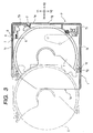
- Fig. 3 is a top sectional view of the disk package
- Fig. 4 is a partially perspective view of a tray
- Fig. 5 is a bottom perspective view of the disk package.
- the disk unit shown in Fig. 1 and Fig. 2 is rectangular in the top view of a main housing A which comprises an device body.
- a main housing A which comprises an device body.
- a disk package P mounting area B and a disk drive area C;
- a disk driving means E is provided for driving a disk D drawn out of the disk package P.
- the disk package P is inserted into the main housing A of the disk unit, in the direction X1 of Fig. 1 and Fig. 2 from the front in the longitudinal direction of a rectangular shape.
- the disk package P can contain a plurality of 120 mm-diameter disks and 80 mm-diameter disks. Furthermore, both a playback-only ROM disk and a recordable RAM disk are housed together.
- the ROM disks are CD and DVD-ROM, while the RAM disks are PD and DVD-RAM.
- the 80 mm-diameter disk is a single CD.
- the disk package P has a synthetic resin casing 1.
- the casing 1 is provided with an opening section la on the left side in Fig. 3 and Fig. 5.
- the opening section la is an outlet for drawing out the tray T and the disk D.
- the casing 1 In the casing 1 are housed a plurality of trays T, which can freely be drawn out. In the depicted example, the casing 1 can accommodate five trays T. On the inner surface of the left side plate 1b and right side plate 1c of the casing 1 a plurality of unillustrated horizontal ribs are protrusively formed. The right and left side edge portions of each tray T are guided between the horizontal ribs, each tray T being slidable in the X direction.
- a restricting projection T1 is formed on the right end and a restricting projection T2 is protrusively formed on the left end; and on the inner surface of the left side plate 1b of the casing 1 a stopper projection ld is integrally formed between these restricting projections T1 and T2.
- a recording medium detected section 6 On the other side edge (the upper side edge in the drawing), there is provided a recording medium detected section 6 as shown in Fig. 4.
- a locking mechanism 7 On the inner surface of the right side plate 1c of the casing 1, a locking mechanism 7 is provided as shown in Fig. 3.
- the recording medium detected section 6 is comprised of a clip K which can be extended out in the direction in the drawing.
- the clip K can be set to extend by two steps out in the Y direction; for instance when a ROM disk is to be mounted in the tray T, the clip K is pressed fully in the Y direction, being set in a position in which the clip K will not project out in the Y2 direction over the side edge of the tray T.
- the clip K When a RAM disk is mounted, the clip K is set in a position where the clip K will project out in the Y2 direction over the side edge of the tray T.
- the clip K set as stated above will be engaged with the locking mechanism 7 when the tray T is drawn out, thereby locking all the tray T from projecting out of the casing 1.
- the clip K will not be engaged with the locking mechanism 7, and therefore the tray T can easily be drawn out.
- the tray T can not be easily drawn out, thereby enabling to prevent accidental interchange between the RAM and ROM disks even in the case of a third person's misoperation and also to prevent impairing or staining the recording surface of the RAM disk.
- the locking mechanism 7 is moved up or down to unlock the clip K by means of an unillustrated unlocking mechanism; thus the tray T mounted with the RAM disk becomes ready to be drawn out to the disk drive area C. Therefore, at the point of time the disk package P is mounted, the disks D, regardless of RAM or ROM disks, can freely be transferred between the disk drive means E and the tray T.
- a holding projection T3 is protrusively and unitarily formed. Inside of the right front plate le of the casing 1 in the drawing, there is provided a plate spring 2 for holding the holding projection T3 of each tray T.
- slits S comprising a plurality of through holes, in a position corresponding to the medium detected section 6, in the right side plate lc of the casing 1.
- the number of the slits S is the same as the number of the trays T provided in the casing 1. Also, as shown in Fig. 3, in the state that the tray T is held within the casing 1, the clip K and the slits S are oppositely located.
- the guide grooves 4 shown in Fig. 5 are formed in two directions of X and Y.
- the guide groove 4 formed in the direction of X axis is used when inserting the disk package P in the X1 direction in relation to the device body (disk unit) as shown in Fig. 1.
- the guide groove 4 formed in the direction of Y axis is for use in the disk unit in which the disk package P is inserted in the Y1 direction.
- lock grooves 4b are formed on the guide groove 4, as described later on, is utilized as a guide primarily for insertion of the disk package.
- Fig. 6 is a bottom perspective view of the disk unit, showing the mechanical structure provided at the bottom of the package mounting area of the housing.
- Numeral 11 in Fig. 6 denotes a lock member formed of a synthetic resin by an injection molding process.
- the lock member 11 is rotatable on the fulcrum of the spindle 11a, and is pressed in the direction ⁇ 1 in the drawing by a pressing member S1 such as a coil spring installed between a hole llb formed in the lock member 11 and a locking section 12 formed by bending from the housing A.
- the forward end llc of the lock member 11 is bent in the Z1 direction in the drawing, being inserted into a sectorial hole 13 made in the housing A. Therefore the lock member 11 is rotatable substantially within the range of the sectorial hole 13.
- On the forward end llc an approximately triangular projecting portion lld is unitarily formed, projecting toward the disk package P mounting area B in the Z1 direction in the drawing.
- an ejection plate 14 is provided.
- the ejection plate 14 is a press-formed metal plate, and has four V-shaped sliding portions 14a on the end side in the X1 and X2 directions, so that the ejection plate 14 is movable on the bottom section B1 in the X direction in the drawing.
- a T-shaped receiving section 14b which is bent in the Z1 direction in the drawing.
- the receiving section 14b is inserted in a guide groove 15 formed in the bottom section B1.
- the ejection plate 14 has a guide groove 14d, in which a T-shaped projection 17 bent from the bottom section B1 is inserted. The ejection plate 14, therefore, is guided along the guide groove 15 and the guide groove 14d, moving straight in the X direction.
- Numeral 18 denotes a drive pin 19 provided on one end of the interlock arm; the drive pin 19 is inserted in the long hole 14e.
- the interlock arm 18 is produced of an approximately K-shaped metal plate by the punching process, and is rotatably supported on a pivot 20. The other end extends in the X2 direction in the drawing. On this end is formed a moving member 18a bent in the Z1 direction in the drawing along the side face Al of the main housing A. As shown in Fig. 6 to Fig.
- a torsion spring 21 is inserted over the pivot 20 of the interlock arm 18 and the torsion spring 21 is retained at one end by the locking section 22 formed by bending on the bottom section B1, and at the other end by the locking section 18b of the interlock arm 18. Therefore, the interlock arm 18 is pressed in the counterclockwise direction in the drawing.
- a projection 23 is formed in contact with the drive pin 19 as shown in Figs. 7 and 8, thereby restricting the clockwise rotation of the interlock arm 18. Also, as the interlock arm 18 is pressed clockwise, a first force F1 is exerted to the moving member 18a in a direction in which the moving member 18a moves away from the side face Al. Furthermore, as shown in Fig. 6, a detecting mechanism 25 is mounted on the side face Al of the main housing A.
- a first spindle 26 is provided in support sections 28, 28 formed by bending in the Y2 direction in the drawing from the side face Al of the main housing A.
- a holder member 29 is rotatably supported on this first spindle 26 .
- the holder member 29 has a fixed second spindle 27, on which a plurality of detecting arms 30 are rotatably mounted.
- a second force F2 turning on the center of the first spindle 26 is applied to the second spindle 27 in the clockwise direction in the drawing (in a direction in which the second spindle 27 approaches the side face A1 of the main housing A); in this state the moving member 18a of the interlock arm 18 is being pressed by the extended portion extending in the Z2 direction in the drawing.
- the first force 1 acting on the moving member 18a is greater than the second force F2 (F1 > F2), the holder member 29 is off the side face Al and the second spindle 27 is off the disk mounting area Bin the wait position, thus keeping balance as shown in Fig. 9 described later.
- the second force F2 is realized by inserting a coil spring S2 over the extended end of the first spindle 26 in the Z2 direction as shown in Fig. 3, with its one end retained on the second spindle 27 and the other end retained on the retaining projection 40 on the bottom section B1.
- the detecting arm 30, as shown in Fig. 9, is comprised of a turning portion (support portion) 30a at center, a detecting pawl (detecting portion) 30b curved towards the side face Al on one side of this turning portion 30a and a pressing portion (base portion) 30c extended on the other side. These members are unitarily molded of a synthetic resin.
- the detecting arm 30 is rotatably supported on the second spindle 27 at the turning portion 30a.
- the detecting pawl 30b is positioned oppositely to the through hole A2 provided in the side face Al; with the counterclockwise turn of the detecting arm 30, the detecting pawl 30b passes the side face Al to approach the disk package P side.
- the pressing portion 30c faces the detecting switch 32 located on the side face Al.
- the detecting arm 30, turning clockwise, can depress each of a plurality of pushbuttons 32a provided on the detecting switch 32.
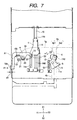
- Fig. 7 is a bottom view showing the disk package inserted halfway; and Fig. 8 is a bottom view showing the state of an interlock arm after the completion of disk package insertion.
- the detecting mechanism 25 is not shown.
- the disk package P is inserted in the insertion port A0 of the housing A in the X1 direction in the drawing as shown in Fig. 2.
- the relationship between the bottom surface lf of the disk package P and the bottom section B1 of the mounting area B is as follows.
- the approximately triangular projection lld formed on the lock member 11 contacts the inclined portion 4a forming the expanded portion 4a shown in Fig. 5. Then the projection lld is turned in the a2 direction in Fig. 4 along the inclined portion 4a1. When the disk package P is inserted, the projection lld slides along the guide groove 4, coming as far as the lock groove 4b. The lock member 11 is turned in the ⁇ 1 direction by the force of the pressing member S1 shown in Fig. 8, and accordingly the projection 11d enters the lock groove 4b, thus being in the locked state a . As the disk package P is locked by the locking mechanism, the insertion of the disk package P into the mounting area B is accomplished.
- the ejection plate 14 before the insertion of the disk package P, is pressed by the pressing member S2, being held in the extreme end on the X2 side indicated by code c .
- the edge lg of the casing 1 contacts the receiving portion 14b of the ejection plate 14.
- the receiving portion 14b is pushed by the edge 1g towards the depth of the mounting area B. Therefore, the ejection plate 14 moves in the X1 direction in the drawing against the force of the pressing member S2.
- the disk package P after completion of insertion, reaches the position indicated by code d shown in Fig. 8. At this time, the projection 11d of the lock member 11 fits in the lock groove 4b as described above, thereby locking the disk package P.
- the drive pin 19 contacts the projection 23, in which position e the interlock arm 18 has been turned fully in the clockwise direction.
- the drive pin 19 slides in the long hole 14e when the ejection plate 14 moves in the X1 direction. Then, when the ejection plate 14 has reached the d position, the drive pin 19 is pressed by the edge on the X2 side of the long hole 14e, slightly turning counterclockwise as indicated by code f in the drawing.
- the amount of projection of the moving member 18a provided on the forward end of the interlock arm 18 varies.
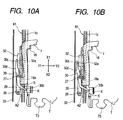
- Fig. 9 is a bottom view showing the state of the detecting mechanism 25 before the mounting of the disk package; and Fig. 10 shows the state of the detecting mechanism 25 after the completion of mounting of the disk package, in which Fig. 10A shows the state of detection of a RAM disk, and Fig. 10B shows the state of detection of a ROM disk.
- the second spindle 27 moves slightly in the Y1 direction, and the detecting arm 30 is turned clockwise by the inner wall restraint section of the exterior housing 33, to thereby retreat the detecting pawl 30b. Therefore, the amount of movement of the second spindle 27 in the Y1 direction decreases, enabling mounting the detecting mechanism 25 in a narrow space. It is, therefore, unnecessary to use a spring for each of the detecting arms 30 to turn the detecting arm 30 clockwise in Fig. 9, thereby resulting in a decreased quantity of component parts.
- the disk package P is as shown in Fig. 10A or Fig. 10B.
- Fig. 10A the RAM disk is set in the tray T; in this state, the clip K provided on the side edge of the tray T is stuck out.
- the interlock arm 18 turns to the f position and the moving member 18a protrudes by the amount of projection dl. Therefore, the holder member 29 is turned clockwise by the action of the second force, causing the second spindle 27 to approach in the direction of the side face Al.
- the back section 30d on the pressing portion 30c moves away from the inner wall restraint section of the exterior housing 33. Therefore, the clockwise pressure acting on the detecting arm is released to free the detecting arm.
- the through hole A2 provided in the side face A1 of the housing A and the slit S provided in the right side plate 1c of the casing 1 face each other. Then, as the second spindle 27 approaches in the direction of the side face Al, the detecting pawl 30b of the detecting arm 30 goes through the through hole A2 and the slit S to come into contact with the clip K which has been stuck out.
- the type of a disk package can be grasped by the ON/OFF state of the pushbutton 32a which is outputted according to the projected state of the clip K provided on the tray T.
- a disk drive means E it is unnecessary to mount a disk in a disk drive means E to read TOC data by an optical head, or to detect a difference in thickness from the cover surface of the disk to the recording surface, or to detect track density.
- the disk package P can be taken out by the following procedure.
- an eject button provided on a operation panel of the disk unit or a remote control unit is operated.
- an unlock lever L shown in Fig. 8 is moved in the X2 direction in the drawing by an unillustrated unlocking mechanism, thus pushing the projection lle protrusively provided on the locking member 11. Therefore, the locking member 11 turns in the ⁇ 2 direction in the drawing, to thereby release the projection lld from the lock groove 4b to unlock the disk package P into the unlock state b .
- the ejection plate 14 is moved in the X2 direction in the drawing by the restoring force of the pressing member S2, so that the receiving portion 14b provided on the forward end of the ejection plate 14 pressed the edge lg of the disk package P in the X2 direction. Therefore, the disk package P is ejected at the insertion port A0 with the movement of the ejection plate 14 from the d position to the c position.
- the interlock arm 18 returns from the f position to the e position. Therefore, the moving member 18a is pushed again by the first force F1 in a direction in which the first spindle 26 will move away from the side face A1 of the main housing A.
- the holder member 29 is turned to move the detecting arm 30 to the standby position which is apart from the side face A1.
- the 30d of the pressing portion 30c side of the detecting arm 30 contacts the inner wall of the exterior chassis 33, being slightly pressed clockwise.
- the detecting arm 30, as heretofore described, is slightly turned clockwise and the detecting pawl 30b is ready to be drawn fully out of the slit S.
- the disk package P ejecting operation can smoothly be performed.
- the detecting portion of the detecting arm comes off from the package mounting area. Therefore, the load at the time of package insertion is not increase, and the detecting arm will neither get fatigued and broken.
Landscapes
- Feeding And Guiding Record Carriers (AREA)
- Automatic Disk Changers (AREA)
- Packaging For Recording Disks (AREA)
Applications Claiming Priority (2)
| Application Number | Priority Date | Filing Date | Title |
|---|---|---|---|
| JP9269714A JPH11110894A (ja) | 1997-10-02 | 1997-10-02 | 記録媒体の識別装置 |
| JP269714/97 | 1997-10-02 |
Publications (1)
| Publication Number | Publication Date |
|---|---|
| EP0907171A1 true EP0907171A1 (de) | 1999-04-07 |
Family
ID=17476155
Family Applications (1)
| Application Number | Title | Priority Date | Filing Date |
|---|---|---|---|
| EP98307898A Withdrawn EP0907171A1 (de) | 1997-10-02 | 1998-09-29 | Vorrichtung zur Identifizierung eines Aufzeichnungsmediums |
Country Status (5)
| Country | Link |
|---|---|
| US (1) | US6154423A (de) |
| EP (1) | EP0907171A1 (de) |
| JP (1) | JPH11110894A (de) |
| KR (1) | KR100269991B1 (de) |
| TW (1) | TW407260B (de) |
Families Citing this family (2)
| Publication number | Priority date | Publication date | Assignee | Title |
|---|---|---|---|---|
| JP2006048741A (ja) * | 2004-07-30 | 2006-02-16 | Fuji Photo Film Co Ltd | 記録ディスクカートリッジ |
| JP2007149316A (ja) * | 2005-11-02 | 2007-06-14 | Alps Electric Co Ltd | 薄膜磁気ヘッド素子の検査方法及び検査用保持治具 |
Citations (3)
| Publication number | Priority date | Publication date | Assignee | Title |
|---|---|---|---|---|
| EP0265167A2 (de) * | 1986-10-15 | 1988-04-27 | Pioneer Electronic Corporation | Plattenwiedergabegerät mit Plattenmagazin |
| JPH0676453A (ja) * | 1992-08-28 | 1994-03-18 | Fujitsu Ten Ltd | オートチェンジ機能を有する記録媒体の再生装置 |
| EP0717405A2 (de) * | 1994-12-14 | 1996-06-19 | Matsushita Electric Industrial Co., Ltd. | Automatisches Plattenwechselgerät und Plattenträger für das Gerät |
Family Cites Families (10)
| Publication number | Priority date | Publication date | Assignee | Title |
|---|---|---|---|---|
| US4021856A (en) * | 1974-12-24 | 1977-05-03 | Olympus Optical Co., Ltd. | Cassette tape recorder |
| US4158865A (en) * | 1975-01-24 | 1979-06-19 | Olympus Optical Company Ltd. | Automatic switching device for cassette tape recorder |
| US4799116A (en) * | 1985-09-09 | 1989-01-17 | Sony Corporation | Apparatus for controlling an auto-reverse tape recorder having a mode-changing mechanism |
| JP2771711B2 (ja) * | 1991-04-22 | 1998-07-02 | 三洋電機株式会社 | カセット装着及び記録判別装置 |
| US5371644A (en) * | 1991-08-12 | 1994-12-06 | Storage Technology Corporation | Self identifying universal data storage element with human intelligible write protect mechanism |
| TW209901B (de) * | 1992-01-27 | 1993-07-21 | Sony Co Ltd | |
| JPH06195852A (ja) * | 1992-04-20 | 1994-07-15 | Teac Corp | ディスク装置 |
| KR0175335B1 (ko) * | 1992-08-28 | 1999-04-15 | 구쯔사와 겐다로오 | 디스크 선택식 플레이어 |
| JPH06223460A (ja) * | 1993-01-28 | 1994-08-12 | Sharp Corp | 記録再生装置 |
| US6031811A (en) * | 1995-06-26 | 2000-02-29 | Matsushita Electric Industrial Co., Ltd. | Arrangement of subtrays in a main tray of an optical disc drive apparatus |
-
1997
- 1997-10-02 JP JP9269714A patent/JPH11110894A/ja not_active Withdrawn
-
1998
- 1998-09-14 TW TW087115285A patent/TW407260B/zh not_active IP Right Cessation
- 1998-09-29 EP EP98307898A patent/EP0907171A1/de not_active Withdrawn
- 1998-09-30 KR KR1019980040934A patent/KR100269991B1/ko not_active Expired - Fee Related
- 1998-10-02 US US09/165,903 patent/US6154423A/en not_active Expired - Fee Related
Patent Citations (3)
| Publication number | Priority date | Publication date | Assignee | Title |
|---|---|---|---|---|
| EP0265167A2 (de) * | 1986-10-15 | 1988-04-27 | Pioneer Electronic Corporation | Plattenwiedergabegerät mit Plattenmagazin |
| JPH0676453A (ja) * | 1992-08-28 | 1994-03-18 | Fujitsu Ten Ltd | オートチェンジ機能を有する記録媒体の再生装置 |
| EP0717405A2 (de) * | 1994-12-14 | 1996-06-19 | Matsushita Electric Industrial Co., Ltd. | Automatisches Plattenwechselgerät und Plattenträger für das Gerät |
Non-Patent Citations (1)
| Title |
|---|
| PATENT ABSTRACTS OF JAPAN vol. 018, no. 330 (P - 1758) 22 June 1994 (1994-06-22) * |
Also Published As
| Publication number | Publication date |
|---|---|
| JPH11110894A (ja) | 1999-04-23 |
| KR100269991B1 (ko) | 2000-10-16 |
| KR19990036723A (ko) | 1999-05-25 |
| US6154423A (en) | 2000-11-28 |
| TW407260B (en) | 2000-10-01 |
Similar Documents
| Publication | Publication Date | Title |
|---|---|---|
| US20010010674A1 (en) | Apparatus for driving an optical disc and method thereof | |
| EP1058260A1 (de) | Plattenkassette und plattenspieler | |
| US5953307A (en) | Disk reproducing apparatus for storing a plurality of cartridges | |
| EP0833327B1 (de) | Plattenmagazin | |
| JP3276566B2 (ja) | ディスク装置 | |
| JP3308454B2 (ja) | ディスクパッケージ | |
| JP3308455B2 (ja) | ディスク装置 | |
| EP1033710A1 (de) | Plattenwechslervorrichtung | |
| US6154423A (en) | Recording medium identifying device | |
| KR100300484B1 (ko) | 기록매체카트리지장착장치 | |
| US6570841B1 (en) | Disk cartridge and disk player | |
| US5982734A (en) | Disk package | |
| JP2012009120A (ja) | ディスクチェンジャー | |
| US5959949A (en) | Disk package for storage of multiple disks of different types and locking mechanism dependent on individual disk type | |
| US7162726B2 (en) | Disk apparatus | |
| JP3638804B2 (ja) | マガジン装填式の記録媒体駆動装置 | |
| KR100269990B1 (ko) | 기록매체의 장착장치 | |
| JP3608963B2 (ja) | マガジン装填式の記録媒体駆動装置 | |
| JP3227370B2 (ja) | カートリッジ誤挿入防止装置 | |
| JPH097345A (ja) | 磁気ディスクカートリッジ | |
| JP2000113558A (ja) | 情報機器のオートチェンジャ装置 | |
| JPH06203453A (ja) | ディスクカートリッジ装着装置 | |
| JPH1186500A (ja) | ディスクカートリッジの誤挿入防止構造 |
Legal Events
| Date | Code | Title | Description |
|---|---|---|---|
| PUAI | Public reference made under article 153(3) epc to a published international application that has entered the european phase |
Free format text: ORIGINAL CODE: 0009012 |
|
| AK | Designated contracting states |
Kind code of ref document: A1 Designated state(s): DE FR GB NL |
|
| AX | Request for extension of the european patent |
Free format text: AL;LT;LV;MK;RO;SI |
|
| 17P | Request for examination filed |
Effective date: 19990326 |
|
| AKX | Designation fees paid |
Free format text: DE FR GB NL |
|
| 17Q | First examination report despatched |
Effective date: 20030918 |
|
| GRAP | Despatch of communication of intention to grant a patent |
Free format text: ORIGINAL CODE: EPIDOSNIGR1 |
|
| STAA | Information on the status of an ep patent application or granted ep patent |
Free format text: STATUS: THE APPLICATION IS DEEMED TO BE WITHDRAWN |
|
| 18D | Application deemed to be withdrawn |
Effective date: 20050303 |