EP0907247A2 - Composant électronique et filtre en échelle - Google Patents
Composant électronique et filtre en échelle Download PDFInfo
- Publication number
- EP0907247A2 EP0907247A2 EP98118157A EP98118157A EP0907247A2 EP 0907247 A2 EP0907247 A2 EP 0907247A2 EP 98118157 A EP98118157 A EP 98118157A EP 98118157 A EP98118157 A EP 98118157A EP 0907247 A2 EP0907247 A2 EP 0907247A2
- Authority
- EP
- European Patent Office
- Prior art keywords
- piezoelectric resonator
- piezoelectric
- electrodes
- base member
- electrically conductive
- Prior art date
- Legal status (The legal status is an assumption and is not a legal conclusion. Google has not performed a legal analysis and makes no representation as to the accuracy of the status listed.)
- Withdrawn
Links
Images


Classifications
-
- H—ELECTRICITY
- H03—ELECTRONIC CIRCUITRY
- H03H—IMPEDANCE NETWORKS, e.g. RESONANT CIRCUITS; RESONATORS
- H03H9/00—Networks comprising electromechanical or electro-acoustic elements; Electromechanical resonators
- H03H9/02—Details
- H03H9/05—Holders or supports
- H03H9/10—Mounting in enclosures
- H03H9/1007—Mounting in enclosures for bulk acoustic wave [BAW] devices
- H03H9/1014—Mounting in enclosures for bulk acoustic wave [BAW] devices the enclosure being defined by a frame built on a substrate and a cap, the frame having no mechanical contact with the BAW device
- H03H9/1028—Mounting in enclosures for bulk acoustic wave [BAW] devices the enclosure being defined by a frame built on a substrate and a cap, the frame having no mechanical contact with the BAW device the BAW device being held between spring terminals
-
- H—ELECTRICITY
- H10—SEMICONDUCTOR DEVICES; ELECTRIC SOLID-STATE DEVICES NOT OTHERWISE PROVIDED FOR
- H10N—ELECTRIC SOLID-STATE DEVICES NOT OTHERWISE PROVIDED FOR
- H10N30/00—Piezoelectric or electrostrictive devices
-
- H—ELECTRICITY
- H03—ELECTRONIC CIRCUITRY
- H03H—IMPEDANCE NETWORKS, e.g. RESONANT CIRCUITS; RESONATORS
- H03H9/00—Networks comprising electromechanical or electro-acoustic elements; Electromechanical resonators
- H03H9/15—Constructional features of resonators consisting of piezoelectric or electrostrictive material
- H03H9/17—Constructional features of resonators consisting of piezoelectric or electrostrictive material having a single resonator
- H03H9/178—Constructional features of resonators consisting of piezoelectric or electrostrictive material having a single resonator of a laminated structure of multiple piezoelectric layers with inner electrodes
-
- H—ELECTRICITY
- H03—ELECTRONIC CIRCUITRY
- H03H—IMPEDANCE NETWORKS, e.g. RESONANT CIRCUITS; RESONATORS
- H03H9/00—Networks comprising electromechanical or electro-acoustic elements; Electromechanical resonators
- H03H9/46—Filters
- H03H9/54—Filters comprising resonators of piezoelectric or electrostrictive material
- H03H9/58—Multiple crystal filters
- H03H9/60—Electric coupling means therefor
- H03H9/605—Electric coupling means therefor consisting of a ladder configuration
Definitions
- the present invention relates to electronic components and ladder filters, and more particularly, to an electronic component, such as a ladder filter using a piezoelectric resonator which uses a mechanical resonance of a piezoelectric member.
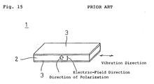
- FIG. 15 is a perspective view of a conventional piezoelectric resonator serving as a background of this invention.
- a piezoelectric resonator 1 includes a piezoelectric substrate 2 having, for example, a rectangular plate shape viewed from the top.
- the piezoelectric substrate 2 is polarized in the thickness direction.
- external electrodes 3 are provided on both surfaces of the piezoelectric substrate 2. When a signal is input between the external electrodes 3, an electrical field is applied to the piezoelectric substrate 2 in the thickness direction and the piezoelectric substrate 2 vibrates in the longitudinal direction.
- the piezoelectric resonator shown in Fig. 15 is of an unstiffened type, in which the vibration direction differs from the direction of polarization and the electrical field.
- the electromechanical coupling coefficient of such an unstiffened piezoelectric resonator is lower than that of a stiffened piezoelectric resonator, in which the vibration direction, the direction of polarization, and the direction in which an electrical field is applied are the same.
- An unstiffened piezoelectric resonator has a relatively small frequency difference ⁇ F between the resonant frequency and the antiresonant frequency. This leads to a drawback in which a frequency bandwidth in use is narrow when an unstiffened piezoelectric resonator is used as a filter. Therefore, the degree of freedom in characteristics design is low in electronic components using such a piezoelectric resonator, including a filter and an oscillator.
- the piezoelectric resonator shown in Fig. 15 uses the first-order resonance in the longitudinal mode. It also generates due to its structure large spurious resonances in odd-number harmonic modes, such as the third-order and fifth-order modes, and in width mode. To suppress these spurious resonances, some measures are considered, such as polishing, increasing mass, and changing the shape of the electrodes. These measures increase manufacturing cost.
- the piezoelectric substrate since when viewed from above the piezoelectric substrate has a rectangular plate shape, the substrate cannot be thinner due to restrictions in strength. Therefore, the distance between the electrodes cannot be reduced and a capacitance between terminals cannot be made large. This is extremely inconvenient for achieving impedance matching with an external circuit.
- a piezoelectric resonator having a lamination structure which excites a longitudinal vibration in a basic mode in which a plurality of piezoelectric layers and a plurality of electrodes are laminated to form a base member having a longitudinal direction, and the plurality of piezoelectric layers are polarized in the longitudinal direction of the base member.
- a piezoelectric resonator having such a lamination structure is of a stiffened type, and has the piezoelectric layers in which the vibration direction, the direction of polarization, and the direction in which an electrical field is applied are the same.
- the piezoelectric resonator has a smaller spurious resonance and a larger difference ⁇ F between the resonant frequency and the antiresonant frequency than an unstiffened piezoelectric resonator.
- a structure shown in Figs. 16 to 20, for example, can be considered.
- Fig. 16 is an exploded perspective view of a ladder filter serving as a background of the present invention.
- Fig. 17 is a plan of the ladder filter
- Fig. 18 is an elevation of the ladder filter.
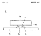
- Fig. 19 is a side view of the ladder filter
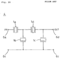
- Fig. 20 is a circuit diagram of the ladder filter.
- four pattern electrodes 6a, 6b, 6c, and 6d are provided on an insulating substrate 5.
- Piezoelectric resonators 1a, 1b, 1c, and 1d having the lamination structure described above are electrically connected to these pattern electrodes 6a to 6d.
- two external electrodes 3a and 3b are provided with a gap in the width direction of each of the piezoelectric resonators 1a, 1b, 1c, and 1d on one side surface of each of the piezoelectric resonators 1a to 1d.
- support members 7 made from an electrically conductive material are provided at the centers of the external electrodes 3a and 3b in the longitudinal direction. These support members 7 are bonded and connected to the pattern electrodes 6a to 6d with electrically conductive adhesive 8.
- This ladder filter 4 has a ladder circuit shown in Fig. 20.
- a metal cap (not shown) is placed to cover the piezoelectric resonators 1a to 1d.
- the piezoelectric resonators 1a to 1d can be surface-mounted on the insulating substrate 5.
- electrically conductive adhesive 8 disposed at adjacent areas may contact each other, electrically conductive adhesive 8 may contact a pattern electrode disposed closely, or electrically conductive adhesive 8 may contact the support member corresponding to adjacent adhesive 8 as shown in Figs. 16 to 18.
- a main object of the present invention is to provide an electronic component having a surface-mountable piezoelectric resonator, in which external electrodes of the piezoelectric resonator are unlikely to be short-circuited.
- Another object of the present invention is to provide a ladder filter having a surface-mountable piezoelectric resonator, in which external electrodes of the piezoelectric resonator is unlikely to be short-circuited.
- the present invention provides an electronic component in which a piezoelectric resonator is disposed on a substrate having at least two mounting electrodes provided on a major surface, characterized in that: said piezoelectric resonator comprising; a base member formed by laminating a plurality of piezoelectric layers and a plurality of inner electrodes; two external electrodes provided on one side surface of said base member and electrically connected to said inner electrodes; said piezoelectric layers being polarized in the longitudinal direction of said base member; and said base member being vibrated in a longitudinal vibration mode, wherein the two external electrodes of said piezoelectric resonator and the two mounting electrodes provided on the major surface of said substrate are connected and secured to each other respectively with electrically conductive bonding members and insulating bonding members disposed in the longitudinal direction of said base member between the external electrodes and the mounting electrodes respectively; and the electrically conductive bonding members which connect and secure the two external electrodes are disposed so as not to be adjacent to each other in the width direction of said
- said piezoelectric resonator and the two mounting electrodes provided on the major surface of said substrate may be connected and secured via a support member made from an electrically conductive material.
- the above electronic component may comprises a plurality of said piezoelectric resonators and three of more of said mounting electrodes connected to the external electrodes of the plurality of piezoelectric resonators.
- a ladder filter may be obtained by the above electronic component.
- the two external electrodes are provided on one side surface of the piezoelectric resonator, and the two external electrodes and the two mounting electrodes provided on the substrate are electrically and mechanically connected and secured with the electrically conductive bonding members and the insulating bonding members. Therefore, in the electronic component and the ladder filter according to the present invention, the piezoelectric resonator is surface-mounted on the substrate.
- the electrically conductive bonding members which electrically connect the two external electrodes of the piezoelectric resonator and the two mounting electrodes provided on the substrate are disposed so as not to be adjacent to each other in the width direction of the base member, these electrically conductive bonding members are unlikely to touch each other. Since these electrically conductive bonding members are isolated by the insulating bonding members which secure the external electrodes and the mounting electrodes, these electrically conductive bonding members do not touch each other and are insulated from each other. Therefore, in the electronic component and the ladder filter according to the present invention, the external electrodes of the piezoelectric resonator are not short-circuited.
- the piezoelectric resonator and the two mounting electrodes provided on the substrate are connected and secured by the use of a support member made from an electrically conductive material.
- the piezoelectric resonator includes a base member formed by laminating a plurality of piezoelectric layers and a plurality of electrodes; two external electrodes electrically connected to the electrodes are provided on one side surface of the base member; and the piezoelectric layers are polarized in the longitudinal direction of the base member and an electric field is applied in the longitudinal direction of the base member to excite longitudinal vibration in the base member, the piezoelectric resonator is of a stiffened type, in which the polarization direction, the direction of the electric field, and the vibration direction are the same.
- the stiffened piezoelectric resonator can have a larger electromechanical coupling coefficient and a larger selection range of the difference ⁇ F between the resonant frequency and the antiresonant frequency.
- vibrations in a mode such as a width mode or a thickness mode, which is different from the longitudinal vibration mode, is unlikely to occur and a spurious resonance becomes small.
- Fig. 1 is an exploded perspective view of an electronic component, a discriminator, according to an embodiment of the present invention.
- Fig. 2 is a plan of the discriminator.
- Fig. 3 is an elevation of the discriminator, and
- Fig. 4 is a side view of the discriminator.
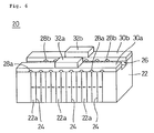
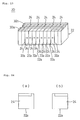
- Fig. 5 is a perspective view of a piezoelectric resonator used in the discriminator shown in Fig. 1.
- Fig. 6 is a view of the piezoelectric resonator, and
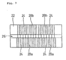
- Fig. 7 is a plan of a main section of the piezoelectric resonator.
- the discriminator 10 shown in Fig. 1 includes, for example, a rectangular-plate-shaped substrate 12.
- the substrate 12 is, for example, made from a resin substrate such as a glass-epoxy substrate, a ceramic substrate such as an alumina substrate, or a multilayer substrate.
- two pattern electrodes 14a and 14b serving as mounting electrodes are provided at a distance. At opposing ends of these pattern electrodes 14a and 14b, lands 16a and 16b are provided.
- a piezoelectric resonator 20 is connected to the lands 16a and 16b of the pattern electrodes 14a and 14b.
- the piezoelectric resonator 20 includes, for example, a rectangular-parallelepiped base member 22.
- the base member 22 includes, for example, a plurality of laminated piezoelectric layers 22a made from piezoelectric ceramic.
- a plurality of internal electrodes 24 are provided at an intermediate portion of the base member 22 in the longitudinal direction. This means that the plurality of internal electrodes 24 are disposed perpendicularly to the longitudinal direction of the base member 22 at certain intervals in the longitudinal direction of the base member 22.
- the plurality of piezoelectric layers 22a disposed at the intermediate portion of the base member 22 in the longitudinal direction are polarized in the longitudinal direction of the base member 22 as shown by arrows in Fig. 6 such that adjacent piezoelectric layers 22a are polarized in opposite directions. Piezoelectric layers 22a disposed at both ends of the base member 22 in the longitudinal direction are not polarized.
- a groove 26 extending in the longitudinal direction of the base member 22 is provided on one side surface of the base member 22.
- the groove 26 is provided at the center in the width direction of the base member 22 and divides the side surface into two parts.
- first insulating films 28a and second insulating films 28b are provided on the side surface divided by the groove 26 .
- the first insulating films 28a cover the exposed portions of alternate internal electrodes 24.
- the second insulating films 28b cover the exposed portions of the other alternate internal electrodes 24, which are not covered by the first insulating films 28a at the one side of the groove.
- the external electrode 30a connects to internal electrodes 24 which are not covered by the first insulating films 28a
- the external electrode 30b connects to internal electrodes 24 which are not covered by the second insulating films 28b.
- adjacent internal electrodes 24 are connected to the external electrodes 30a and 30b, respectively.
- support members 32a and 32b are provided, respectively. These support members 32a and 32b are made from an electrically conductive material.
- the piezoelectric resonator 20 uses the external electrodes 30a and 30b as input and output electrodes. Since the piezoelectric layers disposed at the intermediate section in the longitudinal direction of the base member 22 are polarized between adjacent internal electrodes 24 and an electric field is applied between the adjacent electrodes 24, the piezoelectric layers are piezoelectrically active. In this case, because voltages are applied in opposite directions to the piezoelectric layers 22a constituting the base member 22 which are polarized in opposite directions, the base member 22 expands and contracts in the same direction as a whole. Therefore, the entire piezoelectric resonator 20 vibrates in the longitudinal direction in a basic mode with the center of the base member 22 in the longitudinal direction serving as a node. At both ends of the base member 22 in the longitudinal direction, piezoelectric layers are not polarized and an electric field is not applied due to lack of electrodes, the layers are piezoelectrically inactive.
- the piezoelectric resonator 20 In the piezoelectric resonator 20, the polarization direction of the base member 22, the applied electric field direction due to an input signal, and the direction of vibration in the base member 22 are all the same. In other words, the piezoelectric resonator 20 is of a stiffened type.
- the piezoelectric resonator 20 has a larger electromagnetic coupling coefficient than an unstiffened piezoelectric resonator, in which the direction of vibration differs from the direction of polarization and electric field. Therefore, the piezoelectric resonator 20 has a larger selection range of the frequency difference ⁇ F between the resonant frequency and the antiresonant frequency than an unstiffened piezoelectric resonator. This means that the piezoelectric resonator 20 obtains wide-frequency-band characteristics as compared with an unstiffened piezoelectric resonator.
- the capacitance of the resonator can be adjusted by changing the opposing area of internal electrodes 24, the number of the piezoelectric layers 22a, or the electrodes 24, or the dimensions of the piezoelectric layers 22a in the longitudinal direction of the base member 22.
- the capacitance can be increased by extending the opposing area of internal electrodes 24, by increasing the number of the piezoelectric layers 22a, or the electrodes 24, or by reducing the dimensions of the piezoelectric layers 22a in the longitudinal direction of the base member 22.
- the capacitance can be reduced by reducing the opposing area of internal electrodes 24, by reducing the number of the piezoelectric layers 22a, or the electrodes 24, or by increasing the dimensions of the piezoelectric layers 22a in the longitudinal direction of the base member 22. Therefore, by adjusting the opposing area of internal electrodes 24 in the piezoelectric resonator 20, the number of the piezoelectric layers 22a, or the electrodes 24, or the dimensions of the piezoelectric layers 22a in the longitudinal direction of the base member 22, the capacitance is adjusted. This means that a high degree of freedom is given to capacitance design. Therefore, it is easy to achieve impedance matching with an external circuit when the piezoelectric resonator 20 is mounted on a circuit board.
- one end of one support member 32a in the longitudinal direction of the base member 22 is electrically connected with electrically conductive paste 40 and the other end of the support member 32a is mechanically firmly connected with an insulating member 50 made from an insulating material.
- one end of the other support member 32b, which is disposed adjacently to one end of the support member 32a, in the longitudinal direction of the base member 22 is mechanically firmly connected with the insulating member 50 and the other end of the support member 32b, which is disposed adjacently to the other end of the support member 32a, is electrically connected with the electrically conductive paste 40.
- Urethane or silicone mixed with silver powder for example, can be used for the support members 32a and 32b.
- an electrically conductive material in which epoxy resin is mixed with silver powder is, for example, used for the electrically conductive paste 40
- an insulating material in which epoxy resin is mixed with silica is, for example, used for the insulating member 50. It is preferred that a material having a high thixotropy, which has a low viscosity and tend to flow when stirred at application and which has a high viscosity and is unlikely to flow after the application, be used for the insulating member 50.
- the insulating material for the insulating members 50 is applied first and then the electrically conductive material for the electrically conductive paste 40 is applied to the lands 16a and 16b of the pattern electrodes 14a and 14b, in order that one support member 32a and the land 16a of the pattern electrode 14a are insulated from the electrically conductive paste 40 which electrically connects the other support member 32b to the land 16b of the pattern electrode 14b, with the insulating member 50, and in order that the other support member 32b and the land 16b of the pattern electrode 14b are insulated from the electrically conductive paste 40 which electrically connects one support member 32a to the land 16a of the pattern electrode 14a, with the insulating member 50.
- the electrically conductive paste 40 and the insulating member 50 be provided so as not to touch the piezoelectric resonator 20, in order not to damp the vibration of the piezoelectric resonator 20.
- a metal cap (not shown) is mounted on the substrate 12 so as to cover the piezoelectric resonator 20.
- insulating resin is applied to the substrate 12 and the pattern electrodes 14a and 14b.
- the two external electrodes 30a and 30b are provided on one side surface of the piezoelectric resonator 20, the two support members 32a and 32b made from the electrically conductive material are provided on the two external electrodes 30a and 30b, and the two support members 32a and 32b are electrically and mechanically connected and secured to the two pattern electrodes 14a and 14b on the substrate 12 with the electrically conductive paste 40 and the insulating member 50. Therefore, the piezoelectric resonator 20 is surface-mounted on the substrate 12.
- one support member 32a and one pattern electrode 14a are insulated, with the use of the insulating member 50 which mechanically connects them, from the electrically conductive paste 40 which electrically connects the other support member 32b to the other pattern electrode 14b, and the other support member 32b and the other pattern electrode 14b are insulated, with the use of the insulating member 50 which mechanically connects them, from the electrically conductive paste 40 which electrically connects one support member 32a to one pattern electrode 14a. Therefore, the two external electrodes 30a and 30b of the piezoelectric resonator 20 are unlikely to be short-circuited in this discriminator 10.
- this discriminator 10 includes the piezoelectric resonator 20 which has a small spurious resonance and a large selection range of the difference ⁇ F between the resonant frequency and the antiresonant frequency.
- the piezoelectric resonator 20 Since the piezoelectric resonator 20 is supported in a floating condition from the substrate 12 by the support members 32a and 32b, provided near the node of the piezoelectric resonator 20, in this discriminator 10, the vibration of the piezoelectric resonator 20 is unlikely to be damped.
- the piezoelectric resonator 20 can be easily and positively supported at a condition in which the vibration of the piezoelectric resonator 20 is unlikely to be damped, just by securing the support members 32a and 32b.
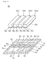
- Fig. 8 is an exploded perspective view of a ladder filter according to the present invention.
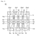
- Fig. 9 is a plan of the ladder filter
- Fig. 10 is an elevation of the ladder filter.
- Fig. 11 is a side view of the ladder filter, and
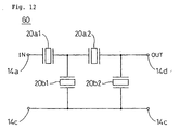
- Fig. 12 is a circuit diagram of the ladder filter.
- the ladder filter 60 shown in Fig. 8 includes, for example, a rectangular-plate-shaped substrate 12.
- pattern electrodes 14a, 14b, 14c, and 14d are provided with gaps.
- Five lands 16a, 16b, 16c, 16d, and 16e are provided in line with gaps on the pattern electrodes 14a to 14d.
- the lands 16a to 16d are provided at ends of the pattern electrodes 14a to 14d, and the land 16e is provided at the other end of the pattern electrode 14b.
- piezoelectric resonator 20a1, 20b1, 20b2, and 20a2 are disposed in line in this order. These piezoelectric resonators 20a1, 20b1, 20b2, and 20a2 have the same structure as the piezoelectric resonator 20 described above. Two piezoelectric resonators 20a1 and 20a2 serve as series resonators, and the other two piezoelectric resonators 20b1 and 20b2 serve as parallel resonator. Therefore, the piezoelectric resonators 20b1 and 20b2, serving as parallel resonators, are designed to have larger capacitances than the piezoelectric resonators 20a1 and 20a2, serving as series resonators.
- one end of the support member 32a of the piezoelectric resonator 20a1 in the longitudinal direction of the piezoelectric resonator 20a1 is electrically connected with electrically conductive paste 40, and the other end of the support member 32a is mechanically firmly connected with an insulating member 50.
- one end of the support member 32b of the piezoelectric resonator 20a1 in the longitudinal direction of the piezoelectric resonator 20a1 and one end of the support member 32a of the piezoelectric resonator 20b1 in the longitudinal direction of the piezoelectric resonator 20b1 are mechanically firmly connected with the insulating member 50, and the other end of the support member 32b of the piezoelectric resonator 20a1 and the other end of the support member 32a of the piezoelectric resonator 20b1 are electrically connected with the electrically conductive paste 40.
- one end of the support member 32b of the piezoelectric resonator 20b1 in the longitudinal direction of the piezoelectric resonator 20b1 and one end of the support member 32a of the piezoelectric resonator 20b2 in the longitudinal direction of the piezoelectric resonator 20b2 are electrically connected with the electrically conductive paste 40, and the other end of the support member 32b of the piezoelectric resonator 20b1 and the other end of the support member 32a of the piezoelectric resonator 20b2 are mechanically firmly connected with the insulating member 50.
- one end of the support member 32b of the piezoelectric resonator 20b2 in the longitudinal direction of the piezoelectric resonator 20b2 and one end of the support member 32a of the piezoelectric resonator 20a2 in the longitudinal direction of the piezoelectric resonator 20a2 are mechanically firmly connected with the insulating member 50, and the other end of the support member 32b of the piezoelectric resonator 20b2 and the other end of the support member 32a of the piezoelectric resonator 20a2 are electrically connected with the electrically conductive paste 40.
- one end of the support member 32b of the piezoelectric resonator 20a2 in the longitudinal direction of the piezoelectric resonator 20a2 is electrically connected with the electrically conductive paste 40, and the other end of the support member 32b is mechanically firmly connected with the insulating member 50.
- the ladder filter 60 has a ladder circuit shown in Fig. 12.
- the pattern electrode 14a serves as an input terminal
- the pattern electrode 14d serves as an output terminal
- the pattern electrode 14c serves as an ground terminal.
- a metal cap (not shown) is mounted on the substrate 12 so as to cover the piezoelectric resonators 20a1, 20b1, 20b2, and 20a2.
- insulating resin is applied to the substrate 12 and the pattern electrodes 14a to 14d such that the metal cap is not electrically connected to the pattern electrodes 14a to 14d.
- the piezoelectric resonators 20a1, 20b1, 20b2, and 20a2 can be surface-mounted on the substrate 12 also in this ladder filter 60.
- the external electrodes 30a and 30b of the piezoelectric resonators 20a1, 20b1, 20b2, and 20a2 are unlikely to be short-circuited also in this ladder filter 60.
- this ladder filter 60 has the piezoelectric resonators 20a1, 20b1, 20b2, and 20a2 each of which has a small spurious resonance and a large selection range in the difference ⁇ F between the resonant frequency and the antiresonant frequency.
- the piezoelectric resonators 20a1, 20b1, 20b2, and 20a2 are supported in a floating condition from the substrate 12 by the support members 32a and 32b provided at the nodes of the resonators in this ladder filter 60, the vibrations of the piezoelectric resonators 20a1, 20b1, 20b2, and 20a2 are unlikely to be damped.
- the piezoelectric resonators 20a1, 20b1, 20b2, and 20a2 can be easily supported in a condition in which the vibrations thereof are unlikely to be damped, just by securing the support members 32a and 32b.
- Attenuation in the ladder filter is determined by the capacitance ratio between the series resonators and the parallel resonators.
- the capacitances can be adjusted by changing the opposing area of internal electrodes 24 in the piezoelectric resonators 20a1, 20b1, 20b2, and 20a2, the number of the piezoelectric layers 22a, or the internal electrodes 24, or the dimensions of the piezoelectric layers 22a in the longitudinal direction of the base member 22.
- a ladder filter having a larger attenuation with fewer resonators is implemented by changing the capacitances of the piezoelectric resonators 20a1, 20b1, 20b2, and 20a2, as compared with a case where unstiffened piezoelectric resonator are used. Since the selection range of the difference ⁇ F in the piezoelectric resonators 20a1, 20b1, 20b2, and 20a2 can be made larger than the conventional piezoelectric resonator, a wider transmission frequency band is implemented as compared with the conventional piezoelectric resonator.
- the grooves 26 are provided at one side surface of the base members 22 in the piezoelectric resonators 20, 20a1, 20a2, 20b1, and 20b2. Such a groove 26 is not necessarily required.
- the support members 32a and 32b are not necessarily required.
- the base member 22 of the piezoelectric resonator 20 may be connected and secured to the lands 16a and 16b of the pattern electrodes 14a and 14b on the substrate 12 with the insulating member 50 and the electrically conductive paste 40.
- soft materials such as urethane and silicone be used for the insulating member 50 and the electrically conductive paste 40 in order that the vibration of the piezoelectric resonator is unlikely to be prevented.
- an electrically conductive material in which urethane or silicone is mixed with silver powder is used for the electrically conductive paste 40
- an insulating material in which urethane or silicone is mixed with silica is used for the insulating member 50. This condition is also applied to the ladder filter 60 described above.
- the metal cap is not necessarily insulated from all the pattern electrodes 14a to 14d on the substrate 12.
- the metal cap may be disposed so as to electrically connect only to the pattern electrode 14c, which is connected to the ground. With such a structure, a shielding effect with the use of the metal cap is obtained.
- Fig. 13 is a view of another piezoelectric resonator.
- Fig. 14 is a plan of electrodes used for the piezoelectric resonator. Unlike the piezoelectric resonator shown in Figs. 5 to 7, alternate internal electrodes 24 are provided on major surfaces of the piezoelectric layers 22a except for one end at an upper section as shown in Fig. 14(a) in the piezoelectric resonator shown in Fig. 13, and the other alternate internal electrodes 24 are provided on major surfaces of the piezoelectric layers 22a except for the other end of the upper section as shown in Fig. 14(b).
- the internal electrodes 24 are provided in this way, one end of an edge of each of the alternate internal electrodes 24 or the other end of the edge of each of the other alternate internal electrodes 24 is not exposed on one side surface of the base member 22. Therefore, unlike the piezoelectric resonator shown in Figs. 5 to 7, the insulating films 28a and 28b are not provided in the piezoelectric resonator shown in Fig. 13. In the present invention, the piezoelectric resonator shown in Fig. 13 may be used.
- both ends of the base member 22 in the longitudinal direction are piezoelectrically inactive.
- Such a portion which is piezoelectrically inactive may be provided at a part of the base member 22 other than both ends thereof in the longitudinal direction.
- the entire base member 22 in the longitudinal direction may be formed to be piezoelectrically active.
Landscapes
- Physics & Mathematics (AREA)
- Acoustics & Sound (AREA)
- Chemical & Material Sciences (AREA)
- Crystallography & Structural Chemistry (AREA)
- Piezo-Electric Or Mechanical Vibrators, Or Delay Or Filter Circuits (AREA)
- Filters And Equalizers (AREA)
Applications Claiming Priority (3)
| Application Number | Priority Date | Filing Date | Title |
|---|---|---|---|
| JP287670/97 | 1997-10-03 | ||
| JP28767097A JP3262050B2 (ja) | 1997-10-03 | 1997-10-03 | 電子部品およびラダーフィルタ |
| JP28767097 | 1997-10-03 |
Publications (2)
| Publication Number | Publication Date |
|---|---|
| EP0907247A2 true EP0907247A2 (fr) | 1999-04-07 |
| EP0907247A3 EP0907247A3 (fr) | 2000-09-06 |
Family
ID=17720208
Family Applications (1)
| Application Number | Title | Priority Date | Filing Date |
|---|---|---|---|
| EP98118157A Withdrawn EP0907247A3 (fr) | 1997-10-03 | 1998-09-24 | Composant électronique et filtre en échelle |
Country Status (6)
| Country | Link |
|---|---|
| US (1) | US6049259A (fr) |
| EP (1) | EP0907247A3 (fr) |
| JP (1) | JP3262050B2 (fr) |
| KR (1) | KR100301718B1 (fr) |
| CN (1) | CN1127211C (fr) |
| NO (1) | NO313357B1 (fr) |
Families Citing this family (4)
| Publication number | Priority date | Publication date | Assignee | Title |
|---|---|---|---|---|
| JP3677673B2 (ja) * | 1999-03-30 | 2005-08-03 | 株式会社村田製作所 | 圧電共振子の保持構造およびそれを有する圧電部品 |
| JP3538709B2 (ja) | 2000-06-14 | 2004-06-14 | 株式会社村田製作所 | 圧電共振部品 |
| JP3473567B2 (ja) * | 2000-10-30 | 2003-12-08 | 株式会社村田製作所 | 圧電共振子およびこの圧電共振子を用いたラダー型フィルタ |
| JP5249561B2 (ja) * | 2007-11-14 | 2013-07-31 | 日本電波工業株式会社 | 圧電振動片及び圧電デバイス |
Family Cites Families (14)
| Publication number | Priority date | Publication date | Assignee | Title |
|---|---|---|---|---|
| DE3038261A1 (de) * | 1980-10-10 | 1982-04-29 | Standard Elektrik Lorenz Ag, 7000 Stuttgart | Baueinheit mit piezoelektrischen resonatoren |
| JPS59117814A (ja) * | 1982-12-24 | 1984-07-07 | Murata Mfg Co Ltd | 圧電磁器共振子 |
| US4532451A (en) * | 1982-12-28 | 1985-07-30 | Murata Manufacturing Co., Ltd. | Terminals and mounting for piezoelectric resonators |
| JPH0270600U (fr) * | 1988-11-15 | 1990-05-29 | ||
| JPH02224515A (ja) * | 1989-02-27 | 1990-09-06 | Tdk Corp | 圧電振動子及びその製造方法 |
| JPH088677A (ja) * | 1994-06-23 | 1996-01-12 | Matsushita Electric Ind Co Ltd | 圧電部品 |
| US6016024A (en) * | 1996-04-05 | 2000-01-18 | Murata Manufacturing Co., Ltd. | Piezoelectric component |
| JPH1079639A (ja) * | 1996-07-10 | 1998-03-24 | Murata Mfg Co Ltd | 圧電共振子およびそれを用いた電子部品 |
| JPH1084244A (ja) * | 1996-07-18 | 1998-03-31 | Murata Mfg Co Ltd | 圧電共振子およびそれを用いた電子部品 |
| JP3577170B2 (ja) * | 1996-08-05 | 2004-10-13 | 株式会社村田製作所 | 圧電共振子とその製造方法およびそれを用いた電子部品 |
| JPH10126203A (ja) * | 1996-08-27 | 1998-05-15 | Murata Mfg Co Ltd | 圧電共振子およびそれを用いた電子部品 |
| JP3147793B2 (ja) * | 1996-11-22 | 2001-03-19 | 株式会社村田製作所 | ラダー型フィルタ |
| JP3570599B2 (ja) * | 1997-01-14 | 2004-09-29 | 株式会社村田製作所 | 圧電素子およびその製造方法 |
| US10249661B2 (en) | 2014-08-22 | 2019-04-02 | Visera Technologies Company Limited | Imaging devices with dummy patterns |
-
1997
- 1997-10-03 JP JP28767097A patent/JP3262050B2/ja not_active Expired - Fee Related
-
1998
- 1998-09-24 EP EP98118157A patent/EP0907247A3/fr not_active Withdrawn
- 1998-09-24 US US09/159,844 patent/US6049259A/en not_active Expired - Fee Related
- 1998-09-29 CN CN98120887A patent/CN1127211C/zh not_active Expired - Fee Related
- 1998-10-02 NO NO19984638A patent/NO313357B1/no not_active IP Right Cessation
- 1998-10-07 KR KR1019980041874A patent/KR100301718B1/ko not_active Expired - Fee Related
Also Published As
| Publication number | Publication date |
|---|---|
| NO313357B1 (no) | 2002-09-16 |
| KR100301718B1 (ko) | 2001-09-06 |
| CN1213896A (zh) | 1999-04-14 |
| JP3262050B2 (ja) | 2002-03-04 |
| NO984638D0 (no) | 1998-10-02 |
| NO984638L (no) | 1999-04-06 |
| CN1127211C (zh) | 2003-11-05 |
| KR19990036912A (ko) | 1999-05-25 |
| US6049259A (en) | 2000-04-11 |
| JPH11112277A (ja) | 1999-04-23 |
| EP0907247A3 (fr) | 2000-09-06 |
Similar Documents
| Publication | Publication Date | Title |
|---|---|---|
| US5900790A (en) | Piezoelectric resonator, manufacturing method therefor, and electronic component using the piezoelectric resonator | |
| EP0800269B1 (fr) | Résonateur piézoélectrique et composant électronique en faisant usage | |
| KR100397745B1 (ko) | 압전 발진기 | |
| US5892416A (en) | Piezoelectric resonator and electronic component containing same | |
| EP0829957B1 (fr) | Résonateur piézoélectrique et composant électronique en faisant usage | |
| US6114800A (en) | Piezoelectric component | |
| EP0820144B1 (fr) | Résonateur piézoélectrique et composant électrique en faisant usage | |
| EP0827273B1 (fr) | Résonateur piézoélectrique et composant électronique utilisant ce résonateur | |
| US5394123A (en) | Ladder type filter comprised of stacked tuning fork type resonators | |
| US6049259A (en) | Electronic component and ladder filter with electrically conductive and insulating bonding members | |
| US5939819A (en) | Electronic component and ladder filter | |
| US6097134A (en) | Piezoelectric resonator and electronic component including same | |
| US6144141A (en) | Piezoelectric resonator and electronic component containing same | |
| KR100299937B1 (ko) | 전자부품및이를이용한통신장치 | |
| US5932951A (en) | Piezoelectric resonator and electronic component containing same | |
| EP0845859B1 (fr) | Résonateur piézoélectrique et composant électronique utilisant ce résonateur | |
| EP0907242A2 (fr) | Composant piézoélectrique | |
| EP0800268B1 (fr) | Résonateur piézoélectrique | |
| EP0907243A2 (fr) | Composant électronique et filtre en échelle | |
| JP2000165181A (ja) | 圧電共振子、電子部品および通信機器 | |
| JPH10107577A (ja) | 電子部品およびラダーフィルタ | |
| JPH11168347A (ja) | 圧電共振子、電子部品および通信機器 |
Legal Events
| Date | Code | Title | Description |
|---|---|---|---|
| PUAI | Public reference made under article 153(3) epc to a published international application that has entered the european phase |
Free format text: ORIGINAL CODE: 0009012 |
|
| 17P | Request for examination filed |
Effective date: 19980924 |
|
| AK | Designated contracting states |
Kind code of ref document: A2 Designated state(s): DE FI FR SE |
|
| AX | Request for extension of the european patent |
Free format text: AL;LT;LV;MK;RO;SI |
|
| PUAL | Search report despatched |
Free format text: ORIGINAL CODE: 0009013 |
|
| AK | Designated contracting states |
Kind code of ref document: A3 Designated state(s): AT BE CH CY DE DK ES FI FR GB GR IE IT LI LU MC NL PT SE |
|
| AX | Request for extension of the european patent |
Free format text: AL;LT;LV;MK;RO;SI |
|
| RIC1 | Information provided on ipc code assigned before grant |
Free format text: 7H 03H 9/17 A, 7H 03H 9/58 B, 7H 03H 9/10 B |
|
| AKX | Designation fees paid |
Free format text: DE FI FR SE |
|
| GRAP | Despatch of communication of intention to grant a patent |
Free format text: ORIGINAL CODE: EPIDOSNIGR1 |
|
| STAA | Information on the status of an ep patent application or granted ep patent |
Free format text: STATUS: THE APPLICATION IS DEEMED TO BE WITHDRAWN |
|
| 18D | Application deemed to be withdrawn |
Effective date: 20051230 |