EP0908249A2 - Drahtziehwerkzeug mit trennbarer Druck- und Ziehmatrize - Google Patents
Drahtziehwerkzeug mit trennbarer Druck- und Ziehmatrize Download PDFInfo
- Publication number
- EP0908249A2 EP0908249A2 EP98111412A EP98111412A EP0908249A2 EP 0908249 A2 EP0908249 A2 EP 0908249A2 EP 98111412 A EP98111412 A EP 98111412A EP 98111412 A EP98111412 A EP 98111412A EP 0908249 A2 EP0908249 A2 EP 0908249A2
- Authority
- EP
- European Patent Office
- Prior art keywords
- die
- pressure
- wire drawing
- wire
- wires
- Prior art date
- Legal status (The legal status is an assumption and is not a legal conclusion. Google has not performed a legal analysis and makes no representation as to the accuracy of the status listed.)
- Granted
Links
Images

Classifications
-
- B—PERFORMING OPERATIONS; TRANSPORTING
- B21—MECHANICAL METAL-WORKING WITHOUT ESSENTIALLY REMOVING MATERIAL; PUNCHING METAL
- B21C—MANUFACTURE OF METAL SHEETS, WIRE, RODS, TUBES, PROFILES OR LIKE SEMI-MANUFACTURED PRODUCTS OTHERWISE THAN BY ROLLING; AUXILIARY OPERATIONS USED IN CONNECTION WITH METAL-WORKING WITHOUT ESSENTIALLY REMOVING MATERIAL
- B21C3/00—Profiling tools for metal drawing; Combinations of dies and mandrels for metal drawing
- B21C3/02—Dies; Selection of material therefor; Cleaning thereof
- B21C3/04—Dies; Selection of material therefor; Cleaning thereof with non-adjustable section
-
- B—PERFORMING OPERATIONS; TRANSPORTING
- B21—MECHANICAL METAL-WORKING WITHOUT ESSENTIALLY REMOVING MATERIAL; PUNCHING METAL
- B21C—MANUFACTURE OF METAL SHEETS, WIRE, RODS, TUBES, PROFILES OR LIKE SEMI-MANUFACTURED PRODUCTS OTHERWISE THAN BY ROLLING; AUXILIARY OPERATIONS USED IN CONNECTION WITH METAL-WORKING WITHOUT ESSENTIALLY REMOVING MATERIAL
- B21C3/00—Profiling tools for metal drawing; Combinations of dies and mandrels for metal drawing
- B21C3/02—Dies; Selection of material therefor; Cleaning thereof
- B21C3/12—Die holders; Rotating dies
-
- B—PERFORMING OPERATIONS; TRANSPORTING
- B21—MECHANICAL METAL-WORKING WITHOUT ESSENTIALLY REMOVING MATERIAL; PUNCHING METAL
- B21C—MANUFACTURE OF METAL SHEETS, WIRE, RODS, TUBES, PROFILES OR LIKE SEMI-MANUFACTURED PRODUCTS OTHERWISE THAN BY ROLLING; AUXILIARY OPERATIONS USED IN CONNECTION WITH METAL-WORKING WITHOUT ESSENTIALLY REMOVING MATERIAL
- B21C3/00—Profiling tools for metal drawing; Combinations of dies and mandrels for metal drawing
- B21C3/02—Dies; Selection of material therefor; Cleaning thereof
- B21C3/12—Die holders; Rotating dies
- B21C3/14—Die holders combined with devices for guiding the drawing material or combined with devices for cooling, heating, or lubricating
Definitions
- the invention consists of an improved tool particularly suited to the pressure wire drawing of wire rods and wires, with a separate and detachable pressure die and drawing die.
- wire drawing well known in the prior art, consists of reducing the diameter of wire rods or wires by means of plastic deformation effected by a tool of appropriate shape known as a wire drawing die.
- Wire is passed through the above mentioned tool by means of electrically driven bobbins so that the diameter of the wire is reduced during this forced passage.
- the length of the entrance cone of the wire drawing die which acts as a pump for the lubricant due to the continuous movement caused by the sliding of the lubricant in the tool, improves the attachment of the lubricant to the wire, but there remain problems of sealing inside the wire drawing die itself.
- wire drawing dies consisting of a single wire drawing core nib made of tungsten carbide encased by shrink-fitting in a case that is carefully shaped on the inside, altogether this constitutes one single piece which is fitted directly on machines designed for wire drawing operations.
- a more recent tool has a case of steel, made of two reversible mating parts, where the upper part is shaped on the inside to house a tungsten carbide die, while the lower part is designed to contain a wire drawing core nib, also made of tungsten carbide, designed to plastically deform the wire rod or wire.
- the dimensions of the tungsten carbide nib which in this case cannot be recovered in any way, are reduced to the indispensable minimum with consequent negative results for lubrication.
- the quality of the finished product and the machining rate are thereby lowered.
- Tools consisting of more than one part that can be assembled and taken apart present the inconvenience of possible leakages of lubricant between the pressure die and the drawing nib as well as that of the steel case yielding due to the high working pressures.
- Production speed in this case too, may not be such as to exploit the maximum potential speed of wire drawing machines due to problems connected with lubrication caused by the above described leakages.
- the object of this invention is to overcome the above drawbacks of the prior art.
- the invention consists therefore of a very reliable and long lasting improved tool particularly suited to the pressure wire drawing of wire rods and wires, with disassemblable pressure die and drawing die, which by optimizing lubrication increases production speeds, lowers costs and thereby improves the entire wire drawing operation.
- an improved tool particularly suited to the pressure wire drawing of wire rods and wires, with disassemblable pressure die and drawing die comprises a disassemblable case having a throughgoing hole, containing a pressure die and a wire drawing core nib which are separate from each other and aligned with said hole, where in at least a gasket is provided between the wire drawing core nib inserted at the bottom of said case and the pressure die located at the top of said case, said gasket being designed to make the passage between said pressure die and said wire drawing core nib leak-proof.
- the improved tool according to the invention is characterized by the features of Claim 1.
- the novel tool suited to the pressure wire drawing of wire rods and wire, with pressure die and drawing die separate and detachable according to the invention, provides the following advantages.
- Lubrication is optimum and without leaks, allowing constantly faster production speeds and therefore a lower overall cost for the finished product.
- a further advantage of the invention is that its great simplicity of manufacture allows the manufacturing costs of its various parts to remain almost unchanged in relation to those already existing for the parts available on the market.
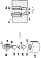
- a first embodiment of the tool 1 particularly suited to the wire drawing of wire rods and wires according to the invention, comprises a case with a hole through the center, preferably made of steel, which has an upper part 2, and a lower part 17.
- Said upper part 2 has a central hole 3 passing through it, forming a first inlet for the wire or wire rod to be drawn and an outer thread 4, for removably engaging the lower part 17.
- a pressure die 5 advantageously made of tungsten carbide, is inserted into said upper part 2.
- This pressure die has a central throughgoing hole 6, the upper section of which has a truncated cone shaped surface 7, which joins a subsequent cylindrical portion 8.
- a wire drawing core nib 10 is located, which is suitably engaged in the lower part 17 of the case of the device 1, according to the invention.
- Said core nib is also advantageously made of tungsten carbide and is provided with a top tapering portion 11, joining a seating 13 provided to house a gasket 9.
- the seating 13 defined moreover a central throughgoing hole 12, which has an inner frustum of cone shaped surface section 14, meeting with a subsequent cylindrical section 15 ending with a tapering section 16.
- the gasket 9, advantageously made of copper, has the function of sealing the joint between the pressure die 5 and the wire drawing nib 10 under all operating conditions.
- the lower part 17 has a cylindrical outer surface and a hole 19 passing through the center of it, with a thread 18 at the top to allow it, as described previously, to be connected to and detached from the upper part 2 and a truncated cone shaped section 20, at the bottom, designed to house the wire drawing nib 10.
- a second embodiment of the tool 21, particularly suited to the wire drawing of wire rods and wires according to the invention comprises a case with a hole through the center, preferably made of steel, which has an upper part 22 and a lower part 34, which can be connected together and detached from each other.
- the upper part 22 has a central hole passing through it, 23, this being the initial entrance for the wire or wire rod to be drawn and a thread 24 on the outside.
- the hole 23 is designed to house a pressure die 25, this too being advantageously made of tungsten carbide.
- This pressure die has a hole 26 passing through the center of it, the upper section of which has a truncated cone shaped surface 27, which joins a subsequent cylindrical shaped surface 28.
- the above mentioned wire drawing nib 30 is inserted into the lower part 34, of the case of the tool 21 according to the invention and the above mentioned hole 31 has a truncated cone shaped inner surface 32 followed by a cylindrical shaped section 33.
- the lower part of the case 34 also has a central hole 35 passing through it with a thread on the inside allowing it to be joined to and detached from the above mentioned upper part 22 of the case.
- the lower part of the case 34 has a truncated cone shaped section 37 designed to house the wire drawing nib 30.
- the wire rod or wire to be drawn is inserted into the entrance hole 3, 23 of the upper part of the case and is passed through the tool 1, 21 according to the invention by means of electric motor driven coils.
- the lubricants mainly used such as oils, soaps and calcium or sodium stearates are also introduced through the entrance hole 3, 23, and are fed along the wire by means of the pump action generated by the continuous movement of the wire and the truncated cone section 7, 27 at the entrance of the pressure die 5, 25, immediately after the entrance hole 3, 23.
- the cooper gasket 9, 29 located between the pressure die 5, 25 and the drawing nib 10, 30, then prevents the above mentioned lubricant from escaping to the outside, keeping it as firmly attached as possible to the wire that is being drawn, thereby guaranteeing optimum lubrication.
- the temperatures and pressures created inside the drawing nib 19, 30 during the operation are considerably different from those found inside the pressure die 5, 25, and consequently the deformation to which these two parts are subject is also different.
- the presence between them of a gasket 9, 29, made of a material with considerably different mechanical properties functions to seal the join between them by exploiting the difference in susceptibility to deformation of the material of which the above mentioned gasket 9, 29 is made and this perfectly compensates for the difference in deformation of the pressure die 5, 25 and the nib 10, 30.
- This also has the advantage of preventing the possible breakage, by bursting, of the outer steel case 1, 21 of the tool according to the invention.
Landscapes
- Engineering & Computer Science (AREA)
- Mechanical Engineering (AREA)
- Metal Extraction Processes (AREA)
- Pressure Welding/Diffusion-Bonding (AREA)
Applications Claiming Priority (3)
| Application Number | Priority Date | Filing Date | Title |
|---|---|---|---|
| IT97MI002273A IT1295287B1 (it) | 1997-10-06 | 1997-10-06 | Utensile perfezionato particolarmente idoneo alla trafilatura a pressione di vergelle e fili metallici,con filiera di pressione e |
| ITMI972273 | 1997-10-06 | ||
| US09/003,384 US5916323A (en) | 1997-10-06 | 1998-01-06 | Pressure wire drawing tool with detachable pressure and drawing dies |
Publications (3)
| Publication Number | Publication Date |
|---|---|
| EP0908249A2 true EP0908249A2 (de) | 1999-04-14 |
| EP0908249A3 EP0908249A3 (de) | 2000-02-23 |
| EP0908249B1 EP0908249B1 (de) | 2003-04-16 |
Family
ID=26331545
Family Applications (1)
| Application Number | Title | Priority Date | Filing Date |
|---|---|---|---|
| EP98111412A Expired - Lifetime EP0908249B1 (de) | 1997-10-06 | 1998-06-22 | Drahtziehwerkzeug mit trennbarer Druck- und Ziehmatrize |
Country Status (3)
| Country | Link |
|---|---|
| US (2) | US5916323A (de) |
| EP (1) | EP0908249B1 (de) |
| IT (1) | IT1295287B1 (de) |
Cited By (2)
| Publication number | Priority date | Publication date | Assignee | Title |
|---|---|---|---|---|
| ITMI20120745A1 (it) * | 2012-05-04 | 2013-11-05 | Dies S A S Di Albino Vanossi & C Van | Trafila aggiustabile |
| EP2796218A1 (de) * | 2013-04-24 | 2014-10-29 | Ceratizit Italia S.p.A. | Ziehmatrizenwerkzeug und Verfahren zur Herstellung eines solchen Werkzeugs |
Families Citing this family (5)
| Publication number | Priority date | Publication date | Assignee | Title |
|---|---|---|---|---|
| ITMI20020466U1 (it) * | 2002-10-11 | 2004-04-12 | Vassena Filiere S R L | Attrezzatura per la trafilatura a freddo di un filo metallico |
| US20080173063A1 (en) * | 2007-01-23 | 2008-07-24 | Thomas Wilson Tyl | Torsional wire treatment drawing system |
| EA033525B1 (ru) * | 2014-07-16 | 2019-10-31 | Vassena Filiere S R L | Оснастка для холодного волочения металлической проволоки |
| WO2017197373A1 (en) * | 2016-05-12 | 2017-11-16 | Paramount Die Company, Inc | Shaped pressure die system |
| CN107497869A (zh) * | 2017-08-25 | 2017-12-22 | 无锡金宸合环机械装备有限公司 | 一种具有密封件的锥形拉丝模 |
Family Cites Families (22)
| Publication number | Priority date | Publication date | Assignee | Title |
|---|---|---|---|---|
| SU11389A1 (ru) * | 1928-02-13 | 1929-09-30 | Э.В. Беляев | Водогрейный прибор |
| US2088040A (en) * | 1936-08-07 | 1937-07-27 | Simons Abraham | Method of and apparatus for wiredrawing |
| US2188470A (en) * | 1936-08-10 | 1940-01-30 | Sheffield Steel Corp | Wire drawing die and die holder |
| US2544302A (en) * | 1945-08-30 | 1951-03-06 | Carboloy Company Inc | Heading die and method of making it |
| US2539716A (en) * | 1948-07-29 | 1951-01-30 | American Steel & Wire Co | Lubricating tungsten carbide die holder |
| FR1139790A (fr) * | 1954-11-30 | 1957-07-04 | Nat Res Dev | Procédé et appareil de tréfilage |
| US3740990A (en) * | 1971-02-16 | 1973-06-26 | Inst Metallurgii Zeleza Imeni | Drawing die assembly with integral cooling system in die housing |
| SU633634A1 (ru) * | 1975-04-08 | 1978-11-25 | Tomshin Mikhail A | Матрица дл гор чего прессовани |
| FR2315330A1 (fr) * | 1975-06-24 | 1977-01-21 | Trefilunion | Filiere de trefilage rotative |
| SU589050A1 (ru) * | 1976-09-10 | 1978-01-25 | Научно-Исследовательский Институт Планирования И Нормативов При Госплане Ссср | Волока |
| SU845927A1 (ru) * | 1978-08-07 | 1981-07-15 | Отдел Физики Полимеров Уральскогонаучного Центра Ah Cccp | Устройство дл волочени с гидро-диНАМичЕСКОй пОдАчЕй СМАзКи |
| US4228673A (en) * | 1978-10-06 | 1980-10-21 | Carmet Company | Die assembly and method of making the same |
| SU799854A1 (ru) * | 1978-10-23 | 1981-01-30 | Донецкий Ордена Трудового Красногознамени Политехнический Институт | Сборна волока |
| SU897360A1 (ru) * | 1980-03-20 | 1982-01-15 | Свердловский Филиал Специального Производственно-Технологического Бюро "Оргпримтвердосплав" | Матрица дл гор чего прессовани |
| GB2077647B (en) * | 1980-06-18 | 1983-06-29 | Uralsky Inst Chernykh Metall | Drawing tool |
| GB2077646B (en) * | 1980-06-18 | 1983-04-07 | Uralsky Inst Chernykh Metall | Drawing tool |
| SU1161212A1 (ru) * | 1983-10-18 | 1985-06-15 | Магнитогорский Метизно-Металлургический Завод | Способ сборки сборных волок |
| SU1304954A1 (ru) * | 1985-07-09 | 1987-04-23 | Предприятие П/Я М-5209 | Устройство дл волочени металла в режиме гидродинамического трени |
| SU1416228A1 (ru) * | 1987-02-02 | 1988-08-15 | Пермский политехнический институт | Способ сборки волок |
| SU1560350A1 (ru) * | 1988-01-14 | 1990-04-30 | Всесоюзный научно-исследовательский институт метизной промышленности | Волочильный инструмент |
| SU1666240A1 (ru) * | 1988-12-21 | 1991-07-30 | Восточный филиал Института черной металлургии | Инструмент дл волочени проволоки |
| US5402664A (en) * | 1993-01-12 | 1995-04-04 | Paramount Die Co., Inc. | Wire drawing die assembly |
-
1997
- 1997-10-06 IT IT97MI002273A patent/IT1295287B1/it active IP Right Grant
-
1998
- 1998-01-06 US US09/003,384 patent/US5916323A/en not_active Expired - Fee Related
- 1998-06-22 EP EP98111412A patent/EP0908249B1/de not_active Expired - Lifetime
-
1999
- 1999-04-13 US US09/290,432 patent/US6374659B1/en not_active Expired - Fee Related
Cited By (2)
| Publication number | Priority date | Publication date | Assignee | Title |
|---|---|---|---|---|
| ITMI20120745A1 (it) * | 2012-05-04 | 2013-11-05 | Dies S A S Di Albino Vanossi & C Van | Trafila aggiustabile |
| EP2796218A1 (de) * | 2013-04-24 | 2014-10-29 | Ceratizit Italia S.p.A. | Ziehmatrizenwerkzeug und Verfahren zur Herstellung eines solchen Werkzeugs |
Also Published As
| Publication number | Publication date |
|---|---|
| EP0908249B1 (de) | 2003-04-16 |
| US5916323A (en) | 1999-06-29 |
| ITMI972273A1 (it) | 1999-04-06 |
| EP0908249A3 (de) | 2000-02-23 |
| US6374659B1 (en) | 2002-04-23 |
| IT1295287B1 (it) | 1999-05-04 |
Similar Documents
| Publication | Publication Date | Title |
|---|---|---|
| EP0908249A2 (de) | Drahtziehwerkzeug mit trennbarer Druck- und Ziehmatrize | |
| US3442537A (en) | Composite forged fitting of diverse metals | |
| CN108790235B (zh) | 机械压力机偏心体连杆复合套瓦温升自动测控装置 | |
| DE10225272B4 (de) | Drehdurchführung | |
| CA1199051A (en) | Load bearing surface | |
| US4785720A (en) | Lubrication mechanism for piston pin and snap ring | |
| US3841129A (en) | Continuous, hydrostatic extrusion process and an apparatus using the same | |
| US3785409A (en) | Clamping apparatus for resistance welding of multiple wires forming a well screen | |
| CN1329135C (zh) | 用于冷拉金属丝的设备 | |
| CN114321535B (zh) | 一种原料废水过滤装置 | |
| CN106513451A (zh) | 一种润滑良好的压力拉丝模 | |
| US5509280A (en) | Latch needle for textile machines | |
| US3695083A (en) | Axial thrust spinning head for rotating dies | |
| SU1225680A2 (ru) | Прессующий поршень машины лить под давлением | |
| SU1592073A1 (ru) | Устройство для гидродинамического волочения изделий | |
| US3606789A (en) | Apparatus for manufacturing a pump spindle | |
| CN219402255U (zh) | 一种组合式压射头 | |
| CN222175895U (zh) | 压力桶进油结构及压铸机 | |
| JPH1119800A (ja) | 機械プレスのプランジャガイド装置 | |
| US3685131A (en) | Method of installing insert ring in pipe unions | |
| DE69813436T2 (de) | Drahtziehwerkzeug mit trennbarer Druck- und Ziehmatrize | |
| CN221109404U (zh) | 一种组装式金属拉丝模具 | |
| SU1736655A1 (ru) | Устройство дл волочени проволоки преимущественно плакированной | |
| SU825223A1 (ru) | УСТРОЙСТВО ДЛЯ ГИДРОДИНАМИЧЕСКСГО ВОЛОЧЕНИЯ ИЗДЕЛИЙ1Устройство относитс к обработке ;мвталлов давлением, в частности к волочению проволоки, прутков, труб и фа- соннык профилей.Известно устройство дл гидродинамического волочени изделий, включающее твердосплавную рабочую волоку и напорную втулку, заключенные в обойму, состо щую из корпуса, зажимной конусной разрезной втулки и накидной гай-ки [1].к недостаткам известного устройства относитс следующее: наличие прорези в зажимной конусной втулке резко снижает надежность уплотнени рабочей полости инструмента из-оа возможности выдавливани смазки; при выходе смазки происходит значительное падение развиваемого давлени , что приводит к нарушению режима гидродинамической смазки, переходу к граничному трению и резкому снижению эффективности волс^и; высокие не- производственные потери смазочного материала удорожают себестоимость еднни-!01520цы продукции, ухудшаютс санитарной^и- гиенических условий работы обслуживающего персонала,. ^Указанные недостатки не позвол ют обеспечить надежную гидродинамическую смазку и ограничивают предельное обжатие стойкость инструмента на износ; повышаютс энергосиловые параметры процесса волочени .Цель изобретени - повышение надежности износостойкости волоки за счет повышени герметичности соединени разрезной втулки с волоками.Поставленна цель достигаетс т&л^чго устройство снабжено утшотнительЕым закладным деформирует^лым элементом из пластичного материала,установленным в прорези зажимной конусной разрезной втутпш. •На фиг, 1 представлена предлагаема волока, продольный разрез; на ф«{г. 2 - разер А—А на фиг. 1.Вопрка состоит из твердосплавной рабочей волоки 1, напорной втулки 2, | |
| CN212318251U (zh) | 一种防氢气压缩机润滑油回流的导油装置及氢气压缩机 |
Legal Events
| Date | Code | Title | Description |
|---|---|---|---|
| PUAI | Public reference made under article 153(3) epc to a published international application that has entered the european phase |
Free format text: ORIGINAL CODE: 0009012 |
|
| AK | Designated contracting states |
Kind code of ref document: A2 Designated state(s): AT BE DE ES FR GB LU NL SE |
|
| AX | Request for extension of the european patent |
Free format text: AL;LT;LV;MK;RO;SI |
|
| PUAL | Search report despatched |
Free format text: ORIGINAL CODE: 0009013 |
|
| AK | Designated contracting states |
Kind code of ref document: A3 Designated state(s): AT BE CH CY DE DK ES FI FR GB GR IE IT LI LU MC NL PT SE |
|
| AX | Request for extension of the european patent |
Free format text: AL;LT;LV;MK;RO;SI |
|
| 17P | Request for examination filed |
Effective date: 20000314 |
|
| AKX | Designation fees paid |
Free format text: AT BE DE ES FR GB LU NL SE |
|
| 17Q | First examination report despatched |
Effective date: 20001204 |
|
| APAB | Appeal dossier modified |
Free format text: ORIGINAL CODE: EPIDOS NOAPE |
|
| GRAG | Despatch of communication of intention to grant |
Free format text: ORIGINAL CODE: EPIDOS AGRA |
|
| GRAG | Despatch of communication of intention to grant |
Free format text: ORIGINAL CODE: EPIDOS AGRA |
|
| GRAH | Despatch of communication of intention to grant a patent |
Free format text: ORIGINAL CODE: EPIDOS IGRA |
|
| GRAH | Despatch of communication of intention to grant a patent |
Free format text: ORIGINAL CODE: EPIDOS IGRA |
|
| GRAA | (expected) grant |
Free format text: ORIGINAL CODE: 0009210 |
|
| AK | Designated contracting states |
Designated state(s): AT BE DE ES FR GB LU NL SE |
|
| PG25 | Lapsed in a contracting state [announced via postgrant information from national office to epo] |
Ref country code: NL Free format text: LAPSE BECAUSE OF FAILURE TO SUBMIT A TRANSLATION OF THE DESCRIPTION OR TO PAY THE FEE WITHIN THE PRESCRIBED TIME-LIMIT Effective date: 20030416 Ref country code: BE Free format text: LAPSE BECAUSE OF FAILURE TO SUBMIT A TRANSLATION OF THE DESCRIPTION OR TO PAY THE FEE WITHIN THE PRESCRIBED TIME-LIMIT Effective date: 20030416 Ref country code: AT Free format text: LAPSE BECAUSE OF FAILURE TO SUBMIT A TRANSLATION OF THE DESCRIPTION OR TO PAY THE FEE WITHIN THE PRESCRIBED TIME-LIMIT Effective date: 20030416 |
|
| REG | Reference to a national code |
Ref country code: GB Ref legal event code: FG4D |
|
| REF | Corresponds to: |
Ref document number: 69813436 Country of ref document: DE Date of ref document: 20030522 Kind code of ref document: P |
|
| PG25 | Lapsed in a contracting state [announced via postgrant information from national office to epo] |
Ref country code: LU Free format text: LAPSE BECAUSE OF NON-PAYMENT OF DUE FEES Effective date: 20030622 |
|
| PG25 | Lapsed in a contracting state [announced via postgrant information from national office to epo] |
Ref country code: SE Free format text: LAPSE BECAUSE OF FAILURE TO SUBMIT A TRANSLATION OF THE DESCRIPTION OR TO PAY THE FEE WITHIN THE PRESCRIBED TIME-LIMIT Effective date: 20030716 |
|
| NLV1 | Nl: lapsed or annulled due to failure to fulfill the requirements of art. 29p and 29m of the patents act | ||
| PG25 | Lapsed in a contracting state [announced via postgrant information from national office to epo] |
Ref country code: ES Free format text: LAPSE BECAUSE OF FAILURE TO SUBMIT A TRANSLATION OF THE DESCRIPTION OR TO PAY THE FEE WITHIN THE PRESCRIBED TIME-LIMIT Effective date: 20031030 |
|
| ET | Fr: translation filed | ||
| PLBE | No opposition filed within time limit |
Free format text: ORIGINAL CODE: 0009261 |
|
| STAA | Information on the status of an ep patent application or granted ep patent |
Free format text: STATUS: NO OPPOSITION FILED WITHIN TIME LIMIT |
|
| 26N | No opposition filed |
Effective date: 20040119 |
|
| PGFP | Annual fee paid to national office [announced via postgrant information from national office to epo] |
Ref country code: DE Payment date: 20080621 Year of fee payment: 11 |
|
| PGFP | Annual fee paid to national office [announced via postgrant information from national office to epo] |
Ref country code: FR Payment date: 20080627 Year of fee payment: 11 |
|
| PGFP | Annual fee paid to national office [announced via postgrant information from national office to epo] |
Ref country code: GB Payment date: 20080625 Year of fee payment: 11 |
|
| GBPC | Gb: european patent ceased through non-payment of renewal fee |
Effective date: 20090622 |
|
| REG | Reference to a national code |
Ref country code: FR Ref legal event code: ST Effective date: 20100226 |
|
| PG25 | Lapsed in a contracting state [announced via postgrant information from national office to epo] |
Ref country code: FR Free format text: LAPSE BECAUSE OF NON-PAYMENT OF DUE FEES Effective date: 20090630 |
|
| PG25 | Lapsed in a contracting state [announced via postgrant information from national office to epo] |
Ref country code: GB Free format text: LAPSE BECAUSE OF NON-PAYMENT OF DUE FEES Effective date: 20090622 |
|
| PG25 | Lapsed in a contracting state [announced via postgrant information from national office to epo] |
Ref country code: DE Free format text: LAPSE BECAUSE OF NON-PAYMENT OF DUE FEES Effective date: 20100101 |