EP0908312A1 - Procede et presse d'impression au cadre - Google Patents
Procede et presse d'impression au cadre Download PDFInfo
- Publication number
- EP0908312A1 EP0908312A1 EP97922191A EP97922191A EP0908312A1 EP 0908312 A1 EP0908312 A1 EP 0908312A1 EP 97922191 A EP97922191 A EP 97922191A EP 97922191 A EP97922191 A EP 97922191A EP 0908312 A1 EP0908312 A1 EP 0908312A1
- Authority
- EP
- European Patent Office
- Prior art keywords
- screen
- squeegee
- printing
- return
- squeegees
- Prior art date
- Legal status (The legal status is an assumption and is not a legal conclusion. Google has not performed a legal analysis and makes no representation as to the accuracy of the status listed.)
- Granted
Links
Images


Classifications
-
- B—PERFORMING OPERATIONS; TRANSPORTING
- B41—PRINTING; LINING MACHINES; TYPEWRITERS; STAMPS
- B41F—PRINTING MACHINES OR PRESSES
- B41F15/00—Screen printers
- B41F15/14—Details
- B41F15/40—Inking units
- B41F15/42—Inking units comprising squeegees or doctors
- B41F15/423—Driving means for reciprocating squeegees
-
- H—ELECTRICITY
- H05—ELECTRIC TECHNIQUES NOT OTHERWISE PROVIDED FOR
- H05K—PRINTED CIRCUITS; CASINGS OR CONSTRUCTIONAL DETAILS OF ELECTRIC APPARATUS; MANUFACTURE OF ASSEMBLAGES OF ELECTRICAL COMPONENTS
- H05K3/00—Apparatus or processes for manufacturing printed circuits
- H05K3/10—Apparatus or processes for manufacturing printed circuits in which conductive material is applied to the insulating support in such a manner as to form the desired conductive pattern
- H05K3/12—Apparatus or processes for manufacturing printed circuits in which conductive material is applied to the insulating support in such a manner as to form the desired conductive pattern using thick film techniques, e.g. printing techniques to apply the conductive material or similar techniques for applying conductive paste or ink patterns
- H05K3/1216—Apparatus or processes for manufacturing printed circuits in which conductive material is applied to the insulating support in such a manner as to form the desired conductive pattern using thick film techniques, e.g. printing techniques to apply the conductive material or similar techniques for applying conductive paste or ink patterns by screen printing or stencil printing
- H05K3/1233—Methods or means for supplying the conductive material and for forcing it through the screen or stencil
-
- H—ELECTRICITY
- H05—ELECTRIC TECHNIQUES NOT OTHERWISE PROVIDED FOR
- H05K—PRINTED CIRCUITS; CASINGS OR CONSTRUCTIONAL DETAILS OF ELECTRIC APPARATUS; MANUFACTURE OF ASSEMBLAGES OF ELECTRICAL COMPONENTS
- H05K2203/00—Indexing scheme relating to apparatus or processes for manufacturing printed circuits covered by H05K3/00
- H05K2203/01—Tools for processing; Objects used during processing
- H05K2203/0104—Tools for processing; Objects used during processing for patterning or coating
- H05K2203/0139—Blade or squeegee, e.g. for screen printing or filling of holes
Definitions
- the present invention mainly relates to a screen printing method and apparatus for printing on a circuit board such as a printed circuit board on which an electronic circuit is formed, printing past such as cream solder and past used to form a thick-film circuit.
- JPA 7-89208 discloses the use of reciprocal printing as a screen printing method in an initial period in which a cleaned or a new screen is used.
- FIG. 3 shows this printing method.
- printing from left to right is called forward printing, while printing from right to left is called return printing.
- the forward and return paths are not limited to the left to right and right to left directions, respectively.
- Reference numeral 1 designates a screen
- a squeegee 2 is composed of a pair of a forward squeegee 2a and a return squeegee 2b.
- An amount of cream solder 3 is supplied that can be filled between the squeegees 2a and 2b.
- Reference numeral 4 denotes a screen opening
- 5 is a circuit board subjected to printing.
- the printing operation is described below that is performed in the initial period in which a cleaned screen 1 or a new screen is used.
- the forward squeegee 2a lowers onto the screen 1, moves the cream solder 3 rightward while pressing it against the screen 1 using its tip, and stops after reaching a predetermined position.
- the forward squeegee 2a elevates, and the return squeegee 2b lowers onto the screen 1 to switch the printing direction.
- the return squeegee 2b moves the cream solder 3 leftward while pressing it against the screen 1 using its tip, and stops after reaching a predetermined position.
- the reciprocal printing is completed in this manner, followed by snapping-off.
- the structure has been proposed in which a pair of squeegees 2a and 2b constitute a link structure and vertically seesaw to switch the squeegees as shown in FIG. 3.
- the screen 1 with the printed cream solder 7 collides against the circuit board 5, resulting in nonuniform printing to affect the quality.
- This invention solves this conventional problem and has an object to provide a screen printing method and an apparatus that restrain a screen from behaving as if it is snapped when squeegees are switched, thereby avoiding nonuniformity of reciprocal printing to improve the quality.
- the screen printing method set forth in claim 1 of this invention is characterized in that when reciprocating a forward and a return squeegees on a screen having an opening in a predetermined pattern, the method comprises: the steps of lowering a return squeegee onto a screen from its standby position to abut the screen, while a forward squeegee which has finished its forward printing is abutting the screen; elevating the forward squeegee from the screen after the return squeegee has abutted the screen; and then performing return printing using the return squeegee.
- the forward squeegee is elevated from the screen while the screen is pressed by the return squeegee. Thereby, the screen is prevented from being lifted and returning to its original position as if it is snapped when the forward squeegee is elevated in order for switching the squeegees. As a result, the quality of printed shapes is improved.
- the screen printing method set forth in claim 2 of this invention is characterized in that during normal production, printing is executed by moving either the forward or the return squeegee in only one direction and in that after the end of a step of cleaning the rear surface of the screen or at the start of production after the replacement of the screen due to a change in machine type, printing is executed by reciprocating the squeegees until an arbitrarily-set number of sheets have been printed.
- the arbitrarily-set number of sheets can be set to such number as bing capable of undergoing effective printing by the reciprocal printing which is performed after the end of the step of cleaning the rear surface of the screen or the start of production after the replacement of the screen due to a change in machine type until the quality of printed shapes gets stabilized.
- the screen printing apparatus set forth in claim 3 of this invention is characterized in that when reciprocating a forward and a return squeegees on a screen having an opening in a predetermined pattern, a means for switching printing from forward direction to return direction lowers the return squeegee on the screen before the forward squeegee elevates to its standby position located above the screen, so that the screen can be prevented from being lifted by the forward squeegee.
- the operation for elevating the forward squeegee to its standby position located above the screen and lowering and abutting it on the screen and the operation for elevating the return squeegee to its standby position located above the screen and lowering and abutting it on the screen can be performed without affecting each other.
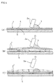
- Embodiments of this invention are described below with reference to FIGS. 1 and 2. Those components that have the same functions as in the prior art have the same reference numerals.
- 1 is a screen
- a squeegee 2 is composed of a pair of a forward squeegee 2a and a return squeegee 2b.
- An amount of cream solder 3 is supplied that can be filled between the squeegees 2a and 2b.
- Reference numeral 4 designates a screen opening
- 5 is a circuit board.
- Reference numeral 6a is a forward-squeegee-elevating actuator
- 6b is a return-squeegee-elevating actuator.
- the actuators 6a and 6b are configured so that they can be individually positioned and controlled.
- an operation of printing the screen 1 is performed as follows until an arbitrarily-set number of sheets are printed.
- the forward squeegee 2a lowers and abuts onto the screen 1, moves the cream solder 3 rightward while pressing it against the screen 1 using its tip, and then stops after reaching a predetermined position.
- FIG. 2(A) shows that the return squeegee 2b lowers and abuts on the screen 1 as shown in FIG. 2(A), and the forward squeegee 2a is then elevated as shown in FIG. 2(B) to switch the printing direction.
- FIG. 2(C) shows that the cream solder 3 has left the forward squeegee 2a.
- the return squeegee 2b moves the cream solder 3 leftward while pressing it against the screen 1 using its tip and stops after reaching a predetermined position.
- the reciprocal printing is completed in this manner, followed by snapping-off.
- This operation enables the forward squeegee to be elevated after the return squeegee has abutted the screen.
- the screen is prevented from being lifted due to the adhesion of the cream solder 3 and from returning to its original position as if it is snapped. Therefore, the quality of printed shapes can be improved.
- printing can be performed by moving either the forward or return squeegee in only one direction.
- the squeegees may be reciprocally moved to print an arbitrarily-set number of sheets.
- the arbitrarily-set number of sheets may be set to such number as bing capable of undergoing effective printing by the reciprocal printing which is performed after the end of the step of cleaning the rear surface of the screen or the start of production after the replacement of the screen due to a change in machine type until the quality of printed shapes gets stabilized.
Landscapes
- Engineering & Computer Science (AREA)
- Mechanical Engineering (AREA)
- Manufacturing & Machinery (AREA)
- Microelectronics & Electronic Packaging (AREA)
- Screen Printers (AREA)
- Electric Connection Of Electric Components To Printed Circuits (AREA)
- Printing Methods (AREA)
Applications Claiming Priority (4)
| Application Number | Priority Date | Filing Date | Title |
|---|---|---|---|
| JP13603096 | 1996-05-30 | ||
| JP136030/96 | 1996-05-30 | ||
| JP8136030A JPH09314799A (ja) | 1996-05-30 | 1996-05-30 | スクリーン印刷方法およびスクリーン印刷装置 |
| PCT/JP1997/001783 WO1997045265A1 (fr) | 1996-05-30 | 1997-05-26 | Procede et presse d'impression au cadre |
Publications (3)
| Publication Number | Publication Date |
|---|---|
| EP0908312A1 true EP0908312A1 (fr) | 1999-04-14 |
| EP0908312A4 EP0908312A4 (fr) | 1999-08-18 |
| EP0908312B1 EP0908312B1 (fr) | 2002-04-10 |
Family
ID=15165549
Family Applications (1)
| Application Number | Title | Priority Date | Filing Date |
|---|---|---|---|
| EP97922191A Expired - Lifetime EP0908312B1 (fr) | 1996-05-30 | 1997-05-26 | Procede et presse d'impression au cadre |
Country Status (5)
| Country | Link |
|---|---|
| EP (1) | EP0908312B1 (fr) |
| JP (1) | JPH09314799A (fr) |
| CN (1) | CN1184072C (fr) |
| DE (1) | DE69711879T2 (fr) |
| WO (1) | WO1997045265A1 (fr) |
Families Citing this family (9)
| Publication number | Priority date | Publication date | Assignee | Title |
|---|---|---|---|---|
| JP3721982B2 (ja) * | 2000-12-04 | 2005-11-30 | 松下電器産業株式会社 | 回路形成基板の製造方法および回路形成基板の製造装置 |
| JP2003334925A (ja) * | 2002-05-21 | 2003-11-25 | Matsushita Electric Ind Co Ltd | スクリーン印刷装置およびスクリーン印刷方法 |
| CN100343048C (zh) * | 2004-01-20 | 2007-10-17 | 东伸工业株式会社 | 平网印花机 |
| JP4391365B2 (ja) * | 2004-09-07 | 2009-12-24 | ヤマハ発動機株式会社 | スクリーン印刷装置 |
| JP4627238B2 (ja) * | 2005-09-29 | 2011-02-09 | ヤマハ発動機株式会社 | スクリーン印刷装置 |
| JP2013043418A (ja) * | 2011-08-26 | 2013-03-04 | Panasonic Corp | スクリーン印刷機及びスクリーン印刷方法 |
| CN104507684B (zh) * | 2012-07-27 | 2016-08-24 | 富士机械制造株式会社 | 丝网印刷机 |
| JP2018134746A (ja) * | 2017-02-20 | 2018-08-30 | 東レエンジニアリング株式会社 | 印刷装置および印刷方法 |
| CN109605914A (zh) * | 2018-12-21 | 2019-04-12 | 北京铂阳顶荣光伏科技有限公司 | 一种丝网印刷装置及丝网印刷设备 |
Family Cites Families (1)
| Publication number | Priority date | Publication date | Assignee | Title |
|---|---|---|---|---|
| JPH03275357A (ja) * | 1990-03-26 | 1991-12-06 | Toshiba Corp | 印刷装置 |
-
1996
- 1996-05-30 JP JP8136030A patent/JPH09314799A/ja active Pending
-
1997
- 1997-05-26 EP EP97922191A patent/EP0908312B1/fr not_active Expired - Lifetime
- 1997-05-26 CN CNB971951918A patent/CN1184072C/zh not_active Expired - Fee Related
- 1997-05-26 DE DE69711879T patent/DE69711879T2/de not_active Expired - Fee Related
- 1997-05-26 WO PCT/JP1997/001783 patent/WO1997045265A1/fr not_active Ceased
Non-Patent Citations (2)
| Title |
|---|
| No further relevant documents disclosed * |
| See also references of WO9745265A1 * |
Also Published As
| Publication number | Publication date |
|---|---|
| DE69711879T2 (de) | 2002-08-08 |
| EP0908312B1 (fr) | 2002-04-10 |
| EP0908312A4 (fr) | 1999-08-18 |
| JPH09314799A (ja) | 1997-12-09 |
| DE69711879D1 (de) | 2002-05-16 |
| CN1220631A (zh) | 1999-06-23 |
| WO1997045265A1 (fr) | 1997-12-04 |
| CN1184072C (zh) | 2005-01-12 |
Similar Documents
| Publication | Publication Date | Title |
|---|---|---|
| KR100301384B1 (ko) | 스크린인쇄방법및스크린인쇄장치 | |
| DE69717460T2 (de) | Verfahren zum steuern einer siebdruckmaschine | |
| DE69715254T2 (de) | Vorrichtung und Verfahren zum Reinigen | |
| EP0908312A1 (fr) | Procede et presse d'impression au cadre | |
| JP7804100B2 (ja) | 印刷処理支援システム | |
| JP3558463B2 (ja) | 印刷方法及び印刷機 | |
| JP2000309081A (ja) | スクリーン印刷方法 | |
| KR100492445B1 (ko) | 스크린인쇄방법및스크린인쇄장치 | |
| JP3384414B2 (ja) | ハンダのスクリーン印刷方法 | |
| JPH11179883A (ja) | クリーム半田印刷装置とその印刷用マスククリーニング方法 | |
| JP3528476B2 (ja) | クリーム半田のスクリーン印刷方法 | |
| JPH0558074A (ja) | 印刷機用スクリーンマスク | |
| JPH0732717A (ja) | 印刷方法 | |
| JP2005067005A (ja) | スクリーン印刷装置 | |
| JPH1044372A (ja) | スクリーン印刷におけるスキージ機構 | |
| JPH11147306A (ja) | スクリーン印刷方法およびスクリーン印刷装置 | |
| JP3685003B2 (ja) | スクリーン印刷方法 | |
| JPH04247687A (ja) | クリーム半田の自動練り方法 | |
| JPH04253393A (ja) | クリームはんだ印刷方法および印刷機 | |
| JP3018443B2 (ja) | スクリーン印刷機 | |
| JPH08332712A (ja) | はんだペースト印刷装置 | |
| JPH0976451A (ja) | インキ供給方法およびそれを用いた印刷機 | |
| JP3478272B2 (ja) | スクリーン印刷方法 | |
| JPH06238869A (ja) | 導体印刷方法及び導体印刷機 | |
| JPH09272271A (ja) | クリーム半田印刷工程管理用マスク、基板実装クリーム半田印刷マスク、及び、これらのマスクを用いたクリーム半田印刷工程管理方法 |
Legal Events
| Date | Code | Title | Description |
|---|---|---|---|
| PUAI | Public reference made under article 153(3) epc to a published international application that has entered the european phase |
Free format text: ORIGINAL CODE: 0009012 |
|
| 17P | Request for examination filed |
Effective date: 19981127 |
|
| AK | Designated contracting states |
Kind code of ref document: A1 Designated state(s): DE GB |
|
| A4 | Supplementary search report drawn up and despatched |
Effective date: 19990706 |
|
| AK | Designated contracting states |
Kind code of ref document: A4 Designated state(s): DE GB |
|
| 17Q | First examination report despatched |
Effective date: 20000301 |
|
| GRAG | Despatch of communication of intention to grant |
Free format text: ORIGINAL CODE: EPIDOS AGRA |
|
| RIC1 | Information provided on ipc code assigned before grant |
Free format text: 7B 41F 15/42 A, 7H 05K 3/12 B |
|
| GRAG | Despatch of communication of intention to grant |
Free format text: ORIGINAL CODE: EPIDOS AGRA |
|
| GRAH | Despatch of communication of intention to grant a patent |
Free format text: ORIGINAL CODE: EPIDOS IGRA |
|
| REG | Reference to a national code |
Ref country code: GB Ref legal event code: IF02 |
|
| GRAH | Despatch of communication of intention to grant a patent |
Free format text: ORIGINAL CODE: EPIDOS IGRA |
|
| GRAA | (expected) grant |
Free format text: ORIGINAL CODE: 0009210 |
|
| AK | Designated contracting states |
Kind code of ref document: B1 Designated state(s): DE GB |
|
| PGFP | Annual fee paid to national office [announced via postgrant information from national office to epo] |
Ref country code: GB Payment date: 20020430 Year of fee payment: 6 |
|
| REF | Corresponds to: |
Ref document number: 69711879 Country of ref document: DE Date of ref document: 20020516 |
|
| PGFP | Annual fee paid to national office [announced via postgrant information from national office to epo] |
Ref country code: DE Payment date: 20020628 Year of fee payment: 6 |
|
| PLBE | No opposition filed within time limit |
Free format text: ORIGINAL CODE: 0009261 |
|
| STAA | Information on the status of an ep patent application or granted ep patent |
Free format text: STATUS: NO OPPOSITION FILED WITHIN TIME LIMIT |
|
| 26N | No opposition filed |
Effective date: 20030113 |
|
| PG25 | Lapsed in a contracting state [announced via postgrant information from national office to epo] |
Ref country code: GB Free format text: LAPSE BECAUSE OF NON-PAYMENT OF DUE FEES Effective date: 20030526 |
|
| PG25 | Lapsed in a contracting state [announced via postgrant information from national office to epo] |
Ref country code: DE Free format text: LAPSE BECAUSE OF NON-PAYMENT OF DUE FEES Effective date: 20031202 |
|
| GBPC | Gb: european patent ceased through non-payment of renewal fee |
Effective date: 20030526 |