EP0908616A2 - Commande de dégazage de vapeur de carburant - Google Patents
Commande de dégazage de vapeur de carburant Download PDFInfo
- Publication number
- EP0908616A2 EP0908616A2 EP98119155A EP98119155A EP0908616A2 EP 0908616 A2 EP0908616 A2 EP 0908616A2 EP 98119155 A EP98119155 A EP 98119155A EP 98119155 A EP98119155 A EP 98119155A EP 0908616 A2 EP0908616 A2 EP 0908616A2
- Authority
- EP
- European Patent Office
- Prior art keywords
- passageway
- outlet
- inlet
- valve
- regulator
- Prior art date
- Legal status (The legal status is an assumption and is not a legal conclusion. Google has not performed a legal analysis and makes no representation as to the accuracy of the status listed.)
- Withdrawn
Links
- 238000010926 purge Methods 0.000 title claims abstract description 87
- 239000000446 fuel Substances 0.000 title claims abstract description 38
- 238000004891 communication Methods 0.000 claims abstract description 38
- 239000012530 fluid Substances 0.000 claims abstract description 23
- 239000002828 fuel tank Substances 0.000 claims description 12
- 230000001276 controlling effect Effects 0.000 claims description 10
- 230000036316 preload Effects 0.000 claims description 10
- 230000001105 regulatory effect Effects 0.000 claims description 7
- 238000002485 combustion reaction Methods 0.000 claims description 6
- 230000000694 effects Effects 0.000 claims description 6
- 230000004907 flux Effects 0.000 claims description 5
- 230000000717 retained effect Effects 0.000 claims description 3
- 238000000638 solvent extraction Methods 0.000 claims description 3
- 238000007789 sealing Methods 0.000 claims description 2
- 238000000034 method Methods 0.000 claims 4
- 238000013022 venting Methods 0.000 claims 1
- 230000004044 response Effects 0.000 abstract description 16
- 230000001965 increasing effect Effects 0.000 description 6
- 229910001868 water Inorganic materials 0.000 description 6
- 239000003610 charcoal Substances 0.000 description 4
- 230000006872 improvement Effects 0.000 description 3
- 230000004048 modification Effects 0.000 description 3
- 238000012986 modification Methods 0.000 description 3
- 230000007423 decrease Effects 0.000 description 2
- 230000003247 decreasing effect Effects 0.000 description 2
- 230000007613 environmental effect Effects 0.000 description 2
- 238000001595 flow curve Methods 0.000 description 2
- 239000000463 material Substances 0.000 description 2
- 238000005192 partition Methods 0.000 description 2
- OKTJSMMVPCPJKN-UHFFFAOYSA-N Carbon Chemical compound [C] OKTJSMMVPCPJKN-UHFFFAOYSA-N 0.000 description 1
- 230000002411 adverse Effects 0.000 description 1
- 230000000712 assembly Effects 0.000 description 1
- 238000000429 assembly Methods 0.000 description 1
- 230000033228 biological regulation Effects 0.000 description 1
- 238000007664 blowing Methods 0.000 description 1
- 229910052799 carbon Inorganic materials 0.000 description 1
- 238000005336 cracking Methods 0.000 description 1
- 230000001186 cumulative effect Effects 0.000 description 1
- 238000011161 development Methods 0.000 description 1
- 230000018109 developmental process Effects 0.000 description 1
- 238000012774 diagnostic algorithm Methods 0.000 description 1
- 239000000428 dust Substances 0.000 description 1
- 238000005516 engineering process Methods 0.000 description 1
- 229930195733 hydrocarbon Natural products 0.000 description 1
- 150000002430 hydrocarbons Chemical class 0.000 description 1
- 230000001939 inductive effect Effects 0.000 description 1
- 230000000670 limiting effect Effects 0.000 description 1
- 238000004519 manufacturing process Methods 0.000 description 1
- 230000007246 mechanism Effects 0.000 description 1
- 230000036961 partial effect Effects 0.000 description 1
- 239000002245 particle Substances 0.000 description 1
- 230000002093 peripheral effect Effects 0.000 description 1
- 230000002829 reductive effect Effects 0.000 description 1
- 230000003068 static effect Effects 0.000 description 1
- 230000007704 transition Effects 0.000 description 1
- XLYOFNOQVPJJNP-UHFFFAOYSA-N water Substances O XLYOFNOQVPJJNP-UHFFFAOYSA-N 0.000 description 1
Images


Classifications
-
- F—MECHANICAL ENGINEERING; LIGHTING; HEATING; WEAPONS; BLASTING
- F02—COMBUSTION ENGINES; HOT-GAS OR COMBUSTION-PRODUCT ENGINE PLANTS
- F02M—SUPPLYING COMBUSTION ENGINES IN GENERAL WITH COMBUSTIBLE MIXTURES OR CONSTITUENTS THEREOF
- F02M25/00—Engine-pertinent apparatus for adding non-fuel substances or small quantities of secondary fuel to combustion-air, main fuel or fuel-air mixture
- F02M25/08—Engine-pertinent apparatus for adding non-fuel substances or small quantities of secondary fuel to combustion-air, main fuel or fuel-air mixture adding fuel vapours drawn from engine fuel reservoir
- F02M25/0836—Arrangement of valves controlling the admission of fuel vapour to an engine, e.g. valve being disposed between fuel tank or absorption canister and intake manifold
-
- F—MECHANICAL ENGINEERING; LIGHTING; HEATING; WEAPONS; BLASTING
- F02—COMBUSTION ENGINES; HOT-GAS OR COMBUSTION-PRODUCT ENGINE PLANTS
- F02M—SUPPLYING COMBUSTION ENGINES IN GENERAL WITH COMBUSTIBLE MIXTURES OR CONSTITUENTS THEREOF
- F02M25/00—Engine-pertinent apparatus for adding non-fuel substances or small quantities of secondary fuel to combustion-air, main fuel or fuel-air mixture
- F02M25/08—Engine-pertinent apparatus for adding non-fuel substances or small quantities of secondary fuel to combustion-air, main fuel or fuel-air mixture adding fuel vapours drawn from engine fuel reservoir
- F02M2025/0845—Electromagnetic valves
Definitions
- the present invention relates generally to fuel vapor purge control for automotive vehicles equipped with computer control evaporative emission systems and more particularly to an electronically controlled variable area purge regulator.
- Virtually all new automotive vehicles manufactured in the United States are equipped with emission control systems that are operable for limiting the emission of hydrocarbons into the atmosphere.
- One aspect of these emission control systems typically involves an evaporative emission control system which traps fuel vapors emitted from the fuel tank in a carbon-filled canister.
- the evaporative emission control system is periodically purged by drawing the fuel vapors from the canister into the engine intake system. In this manner, fuel vapors from the fuel tank are delivered to the engine for subsequent combustion.
- evaporative emission control systems are equipped with a fixed area purge valve for regulating the flow rate of fuel vapors introduced into the intake system in response to the pressure difference between the intake manifold and atmosphere.
- These purge valves utilize a pulse width modulated (PWM) solenoid valve which is responsive to a duty cycle control signal from an engine controller unit (ECU) for selectively establishing and terminating communication between the canister and the intake system.
- PWM pulse width modulated
- ECU engine controller unit
- these purge valves provide uneven flow characteristics, particularly at low engine speeds, and also do not provide consistent flow control independent of variations in manifold vacuum and inlet pressure.
- a vapor management valve which uses a diaphragm vacuum regulator in combination with an electric vacuum regulator (EVR) valve that regulates a vacuum signal in accordance with the current signal supplied thereto by the ECU.
- EMR electric vacuum regulator
- the vapor management valve is able to generate substantially linear output flow characteristics between two calibration points as a function of the solenoid current in a manner that is independent of changes in manifold vacuum of the engine intake system.
- U.S. Patent No. 5,277,167 which is commonly owned by the assignee of the present invention and expressly incorporated by reference herein, discloses a vapor management valve which represents a significant improvement over the conventional PWM solenoid valves.
- the vapor management valve provides an advancement over a wide range of operating conditions, in this technology continuous improvements have been sought particularly with respect to extreme operating conditions. More specifically, the vapor management valve, which is referenced to atmospheric pressure, is designed to withstand relatively high canister pressures without leaking when the engine is off. However, the vacuum generated by the EVR may bias the diaphragm to a near open condition such that relatively low canister pressures (cracking pressure) can possibly open the valve and cause uncommanded purge flow. The vapor management valve also requires a continuous flow of air through the EVR into the intake manifold to operate.
- certain engine operating conditions can result in a cumulative bleed flow which can exceed the desired idle air flow requirements of the engine resulting in excessive and/or fluctuating engine RPM.
- the flow of air into the EVR can be restricted when the intake air filter of the vapor management valve becomes clogged, for example with snow, dust or dirt, or alternately when water is ingested therethrough. If the flow of air is sufficiently restricted, the vapor management valve will not perform as desired.
- the output flow characteristics of the purge valve be continuous and proportional to the duty cycle of the electric control signal applied to the valve, even at low engine speeds, and yet be independent of variations to the inlet pressure and outlet manifold vacuum applied across the valve. Accordingly, the output flow of the valve should be substantially continuous at a given duty cycle control signal and be controllable in response to regulated changes in the duty cycle regardless of these pressure variations. Moreover, it is also desirable that the output flow of the purge regulator vary nonlinearly over the duty cycle range.
- variable area purge valve and pressure regulator of the present invention combines a solenoid valve assembly and a pressure regulator assembly for generating an output flow characteristic that varies as a function of the duty cycle of the electronic control signal and which is independent of variations in the inlet pressure and manifold vacuum.
- Another object of the present invention is to provide a variable area purge regulator which utilizes a pressure regulator assembly to maintain a substantially constant pressure differential across the variable area purge control valve during operation thereof.
- One side of the pressure regulator assembly is referenced to the canister or inlet side of the system so that inlet pressure in the system will tend to close the regulator more tightly.
- a further object of the present invention is to provide a variable area purge valve and pressure regulator which is operative without a bleed flow existing therethrough while being capable of satisfying the desired performance specifications across the entire range of engine operating conditions and is not susceptible to adverse environmental conditions.
- the present invention is directed to improvements in proportional valves of the type used in automotive vehicles for controlling the flow of fluid from a fluid source to a fluid sink. More particularly, a preferred embodiment of an electronically controlled variable area purge regulator is disclosed which is adapted for use in an evaporative emission control system for purging fuel vapors collected in a charcoal canister into the intake system of an internal combustion engine associated with the vehicle.
- an electronically controlled variable area purge regulator is disclosed which is adapted for use in an evaporative emission control system for purging fuel vapors collected in a charcoal canister into the intake system of an internal combustion engine associated with the vehicle.
- the improved purge regulator of the present invention has utility in other flow controlling applications.
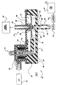
- variable area purge regulator 10 is disclosed as having solenoid valve assembly 12, 112 and pressure regulator assembly 14, 114.
- variable area purge regulator 10 is of the type associated with a conventional evaporative emission control system for an automotive vehicle. More specifically, fuel vapors vented from fuel tank 16 are collected in charcoal canister 18 and are controllably purged by variable area purge regulator 10 into intake manifold 20 of an internal combustion engine in response to electrical control signals supplied to solenoid valve assembly 12 by engine controller unit (ECU) 22.
- ECU engine controller unit
- variable area purge regulator 10 provides a variable area orifice valve assembly which accurately regulates fuel vapor purge flow from canister 18 to intake manifold 20 independent of pressure differences between inlet pressure and manifold vacuum.
- the present invention can be simply and precisely calibrated to meet the desired output flow characteristics across the entire operating range of the engine.
- pressure regulator assembly 14 and solenoid valve assembly 12 are shown assembled as a unitary component, it is to be understood that these assemblies could be separate components that are interconnected for communication therebetween in a known manner.
- purge regulator 10 includes plastic control valve housing 26 having cover 28 secured to body 30 by threaded fasteners 32.
- a pair of o-rings 34, 36 are disposed between cover 28 and body 30 to hermetically seal purge regulator 10.
- Chamber 38 is formed within body 30 and is enclosed by cover 28.
- Pressure regulator assembly 14 is disposed within and partitions chamber 38 to define inlet cavity 40 and outlet cavity 42.
- Nippled inlet connector 44 extending from body 30 has inlet passageway 46 formed therein to provide communication from filter 24 to inlet cavity 40 via inlet passageway 46a.
- nippled outlet connector 48 which extends from cover 28 has outlet passageway 50 formed therein for providing communication between outlet cavity 42 and intake manifold 20.
- the cross-sectional area of outlet passageway 50 increases from outlet cavity 42 toward intake manifold 20 to provide a smooth transition therebetween.
- Solenoid valve assembly 12 selectively controls or modulates fluid communication between inlet passageway 46 and outlet passageway 50 through bypass passageway 52.
- the inlet side of pressure regulator assembly 14 is referenced to the inlet pressure in fuel tank 16.
- the outlet side of pressure regulator assembly 14 is referenced to the pressure downstream of valve assembly 14. In this manner, solenoid valve assembly 12 and pressure regulator assembly 14 are able to maintain a substantially constant pressure differential regardless of fluctuations in the input pressure from fuel tank 16 or outlet pressure from intake manifold 20.
- purge regulator 10 provides a nonlinear relationship between the output flow and the duty cycle. More specifically, purge regulator 10 maintains a substantially linear relationship between the fuel vapor flow and percent duty cycle irrespective of intake manifold vacuum conditions above the fifty percent (50%) duty cycle point. Moreover, purge regulator 10 provides a smooth non-linear relationship between the fuel vapor flow and percent duty cycle at the "start-to-open" portion of the duty cycle, i.e., zero percent (0%) to fifty percent (50%) irrespective of intake manifold vacuum.
- the response of purge regulator 10 is substantially unchanged by the effects of manifold vacuum as illustrated by response curve 202 at 125 mm Hg, response curve 204 at 300 mm Hg, response curve 206 at 405 mm Hg and response curve 208 at 50 mm Hg, the previous pressures being indicated in gage pressure.
- purge regulator 10 maintains a substantially linear relationship between the fuel vapor flow and percent duty cycle irrespective of inlet pressures above the fifty percent (50%) duty cycle point. Moreover, purge regulator 10 provides a smooth non-linear relationship between the fuel vapor flow and percent duty cycle at the "start-to-open" portion of the duty cycle irrespective of inlet pressures.
- the response of purge regulator 10 is substantially unchanged by the effects of inlet pressure as illustrated by response curve 210 at 64 in-H 2 O, response curve 212 at 16 in-H 2 O, response curve 214 at 11 in-H 2 O, response curve 216 at 5 in-H 2 O and response curve 218 at atmospheric pressure or 0 in-H 2 0, the previous pressures being indicated in gage pressure.
- purge regulator 10 further includes solenoid valve assembly 12 disposed within cover 28.
- Solenoid valve assembly 12 includes bobbin 54 formed of a nonmagnetic material having a wire coil 56 wrapped therearound to form a coil assembly having a bore formed therethrough along a central longitudinal axis.
- Flux collector 58 is positioned on a lower adjacent surface of bobbin 54 and pole piece 60 is positioned on an upper adjacent surface of bobbin 54.
- Pole piece 60 further includes a tubular portion 62 extending longitudinally into the bore formed by bobbin 54.
- armature bushing 64 is longitudinally disposed within bobbin 54 and is captured between tubular portion 62 and flux collector 58 for retaining the appropriate orientation thereof.
- Magnetic armature 66 is slidably disposed within armature bushing 64 for reciprocating movement along the central longitudinal axis of solenoid valve assembly 12.
- a lower end 68 of armature 66 tapers to a spherically concaved tip which receives valve ball 70 therein.
- a bypass valve seat 86 is retained in a portion of passageway 52 which receives ball 70 therein. In this way, lower end 68, valve ball 70 and valve seat 86 are configured to provide means for selectively controlling fluid communication between inlet passageway 46 and outlet passageway 50 through a smoothly transitioning flow path to pressure regulator assembly 14.
- lower end 68 of armature 66 could be adapted to include an alternate geometry, such as a rounded or spherically convex tip, a flat tip or a conical tip, and may alternatively eliminate valve ball 70.
- the outer surface of upper end 72 of armature 66 is tapered to provide an approximately linear force-distance curve over the range of reciprocal movement of armature 66 within the electromagnetic coil assembly.
- Second end 72 of armature 66 has a blind bore formed therein for receiving spring 74 which biases solenoid valve assembly toward a closed position.
- Tubular portion 62 of pole piece 60 is internally threaded for receiving calibration screw 76 which engages an end of spring 74 opposite armature 66 and provides means for adjusting a preload in spring 74 for biasing armature 66.
- O-ring 78 is disposed around an upper portion of calibration screw 76 to provide sealing engagement with tubular portion 62 of pole piece 60 to maintain the hermetic seal of purge regulator 10.
- Solenoid housing 80 encloses the components of solenoid assembly 12 between flux collector 58 and pole piece 60 to provide an encapsulated solenoid assembly. Terminal blade 82 is electrically connected to the coil assembly and extends through solenoid housing 80 and connector 84 which extends from cover 28.
- Terminal blade 82 and connector 84 provide an electrical connection between ECU 22 and solenoid valve assembly 12.
- Solenoid valve assembly 12 is captured between cover 28 and body 30 such that tubular portion 62 of pole piece 60 extends through aperture 87 formed in cover 28.
- O-ring 88 circumscribes aperture 87 and is disposed between an inner surface of cover 28 and pole piece 60 to hermetically seal purge regulator 10.
- Pressure regulator assembly 14 of purge regulator 10 includes diaphragm 90 operatively disposed within and partitioning chamber 38. More specifically, annular flange 92 extends downwardly from cover 28 and captures a peripheral portion of diaphragm 90 on a shoulder portion formed in body 30. Piston 94 is disposed on a top surface of diaphragm 90 within outlet cavity 42 for providing rigidity to diaphragm 90. Outlet valve seat 96 is formed at an end of outlet passageway 50 within outlet cavity 42. Outlet valve seal 98 is formed on piston 94 and is engageable with outlet valve seat 96 to selectively control fluid communication between outlet cavity 42 and outlet passageway 50.
- Spring 100 is supported and operatively disposed between cover 28 and piston 94 to provide a preload for biasing outlet valve seal 98 away from outlet valve seat 96.
- pressure regulator assembly 14 is assembled in a net build manner whereby the part to part variation between control valve body 26 and piston 94 are determined by the installed load of spring 100.
- a portion of cover 28 adjacent nippled outlet connector 48 which acts as the upper spring seat could be threadedly coupled to the remainder of cover 28 such that the upper spring seat is axially adjustable along the longitudinal axis of outlet passageway 50 to calibrate the preload in spring 100.
- an upper spring seat which is axially adjustable along the longitudinal axis of outlet passageway 50 could be employed to calibrate the preload in spring 100.
- variable area purge regulator 10 Prior to start-up, variable area purge regulator 10 is in a static condition such that the pressure in outlet cavity 42 is approximately atmospheric and the pressure in inlet cavity 40 is approximately atmospheric or slightly greater than atmospheric due to residual vapor pressure within fuel tank 16. If the pressure differential across pressure regulator assembly 14 exceeds the regulating pressure (50 mm Hg), pressure regulator assembly 14 urges valve seal 98 against valve seat 96, thereby terminating communication between outlet cavity 42 and outlet passageway 50. Otherwise pressure regulator assembly 14 remains open. Solenoid valve assembly 12 is positioned in a closed condition to selectively terminate communication between inlet passageway 46 and passageway 52.
- ECU 22 Upon start up of the vehicle engine, a vacuum is generated within intake manifold 20 drawing from cavity 42 until the pressure differential is sufficient to compress spring 100 and seal valve seat 98. After certain diagnostic algorithms are executed, ECU 22 provides a current proportional to duty cycle for energizing electromagnetic coil 56 to appropriately position armature 66 along the central longitudinal axis of solenoid valve assembly 12, thereby selectively establishing and proportionally controlling fluid communication between inlet passageway 46 and passageway 52. Upon establishment of fluid communication between inlet passageway 46 and passageway 52, fuel vapors which have been collected in canister 18 are drawn through inlet passageway 46 and passageway 52 to pressurize outlet cavity 42.
- valve seal 98 moves away from valve seal 96 such that a force balance between the pressure differential across pressure regulator assembly 14 and spring 100 controls the flow of fuel vapor so as to maintain a substantially constant pressure differential therebetween.
- variations in the area of the orifice defined by valve seat 86 and valve ball 70 will affect the amount of fuel vapor transported through purge regulator 10. As the area of the orifice formed between valve seat 86 and valve ball 70 increases, the fuel vapor flow increases, thereby increasing the pressure in outlet cavity 42.
- inlet cavity 40 of pressure regulator assembly 14 is referenced to the inlet pressure in fuel tank 16, purge regulator 10 operates substantially independent of fluctuations in inlet pressure from fuel tank 16. Furthermore, reference to the inlet pressure prevents pressure regulator 10 from blowing open under high fuel tank pressure conditions. Increased pressure in fuel tank 16 will close pressure regulator assembly 14. Moreover, the combination of solenoid valve assembly 12 and pressure regulator assembly 14 provides a more gradual flow curve over the lower duty cycle settings (e.g. thirty percent to fifty percent), while still maintaining maximum flow requirements. Accordingly, by purposefully inducing a non-linearity into the flow curve, a desirable control feature is achieved because it gives ECU 22 better ability to precisely control low purge flow rates at idle.
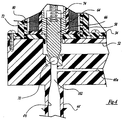
- nippled inlet connector 44' extends downwardly from body 30' and has inlet passageway 46' formed therein.
- Venturi 102 is formed at an intermediate portion of inlet passageway 46' adjacent solenoid valve seat 86.
- Inlet passageway 46' tapers to a diameter approximately equal to the orifice at the bottom of tapered valve seat 86.
- Venturi 102 operates to locally increase the velocity of the flow through inlet passageway 46', thereby decreasing the pressure of the flow within inlet passageway 46'.
- venturi 102 decreases the pressure differential across pressure regulator assembly 14 during high flow conditions and in effect creating a positive feedback system whereby an increase in inlet pressure results in greater flow through purge regulator 10'.
- venturi 102 does not significantly alter the operation of purge regulator 10' during low flow conditions.
- venturi 102 provides a means for tuning purge regulator 10' to yield a more gradual slope at the start-to-open point, i.e. thirty percent to fifty percent (30% - 50%) duty cycle, and increased flow rates at a duty cycle greater than fifty percent (50%).
- variable area purge regulator 110 according to the present invention is illustrated in which inlet passageway 146 is positioned directly adjacent pressure regulator assembly 114 for providing a positive shut-off regulator which terminates communication between inlet passageway 146 and inlet cavity 140 under certain conditions notably when the engine is off. Due to the similarities between the first preferred embodiment illustrated in Figures 1 and 4 and the second preferred embodiment illustrated in Figure 5, like reference numerals incremented by a factor of one hundred (100) will be utilized to identify components which are similar therebetween.
- Variable area purge regulator 110 includes solenoid valve assembly 112 and pressure regulator assembly 114. Fuel vapors vented from fuel tank 116 are collected in charcoal canister 118 and are controllably purged by variable area purge regulator 110 into intake manifold 120 of an internal combustion engine in response to electrical control signals supplied to solenoid valve assembly 112 by ECU 122. Filter 124 may be optionally included in the above-described flow path between canister 118 and variable area purge regulator 110.
- Purge regulator 110 includes plastic control valve housing 126 having cover 128 secured to body 130 by threaded fasteners 132. Chamber 138 is formed within body 130 and enclosed by cover 128. Pressure regulator assembly 114 is disposed within and partitions chamber 138 to define inlet cavity 140 and outlet cavity 142. Control valve housing 126 further includes nipped inlet connector 144 which extends downwardly from body 130 has inlet passageway 146 formed therein. As presently preferred, inlet 202 formed in inlet passageway 146 is reduced to reduce the valve diameter and terminates at inlet cavity 140. Inlet valve seat 204 is formed at an end of inlet passageway 146 adjacent pressure regulator assembly 114. Inlet valve seal 206 is formed on diaphragm 190 and extends towards inlet valve seat 204.
- outlet valve seal 198 extends upwardly from piston 194 and is engageable with outlet valve seat 196.
- pressure regulator assembly 114 is responsive to the pressure differential between inlet cavity 140 and outlet cavity 142 to terminate communication between inlet passageway 146 and inlet cavity 140, or alternately terminate communication between outlet passageway 150 and outlet cavity 142.
- Purge regulator 110 further includes passageway 152a to provide communication from inlet cavity 140 to outlet cavity 142 through passageway 152 via actuation of solenoid valve assembly 112.
- Solenoid valve assembly 112 includes magnetic armature 166 which is slidably disposed within armature bushing 164 for reciprocating movement along the central longitudinal axis of solenoid assembly 112.
- a first end 168 of armature 166 is tapered and terminates at a spherical tip which receives valve ball 170 therein.
- Solenoid valve assembly 112 further includes tapered bypass valve seat 186 disposed within passageway 152a which cooperates with valve ball 170 and armature 166 for selectively controlling and modulating fluid communication between passageway 152 and 152a.
- purge regulator 110 operates in substantially the same manner as purge regulator 10 described above.
- purge regulator 110 is capable of terminating communication between inlet passageway 146 and inlet cavity 140. More specifically, when the pressure differential between inlet cavity 140 and outlet cavity 142 falls below a given level, spring 200 urges inlet valve seal 206 against inlet valve seat 204, thereby terminating communication between inlet passageway 146 and inlet cavity 140. This mechanism provides an effective means of positive shut off of all flow from canister 118 when the engine is not running and manifold vacuum drops to zero.
Landscapes
- Engineering & Computer Science (AREA)
- Chemical & Material Sciences (AREA)
- Combustion & Propulsion (AREA)
- Mechanical Engineering (AREA)
- General Engineering & Computer Science (AREA)
- Supplying Secondary Fuel Or The Like To Fuel, Air Or Fuel-Air Mixtures (AREA)
- Magnetically Actuated Valves (AREA)
Applications Claiming Priority (2)
| Application Number | Priority Date | Filing Date | Title |
|---|---|---|---|
| US08/949,106 US5970958A (en) | 1997-10-10 | 1997-10-10 | Fuel vapor purge control |
| US949106 | 1997-10-10 |
Publications (2)
| Publication Number | Publication Date |
|---|---|
| EP0908616A2 true EP0908616A2 (fr) | 1999-04-14 |
| EP0908616A3 EP0908616A3 (fr) | 2000-02-23 |
Family
ID=25488605
Family Applications (1)
| Application Number | Title | Priority Date | Filing Date |
|---|---|---|---|
| EP98119155A Withdrawn EP0908616A3 (fr) | 1997-10-10 | 1998-10-09 | Commande de dégazage de vapeur de carburant |
Country Status (6)
| Country | Link |
|---|---|
| US (1) | US5970958A (fr) |
| EP (1) | EP0908616A3 (fr) |
| JP (1) | JPH11193756A (fr) |
| KR (1) | KR19990037008A (fr) |
| BR (1) | BR9804361A (fr) |
| CA (1) | CA2248102A1 (fr) |
Cited By (5)
| Publication number | Priority date | Publication date | Assignee | Title |
|---|---|---|---|---|
| WO2001086367A1 (fr) * | 2000-05-05 | 2001-11-15 | Siemens Automotive Inc. | Dispositif integre de gestion de la pression a circuit de commande electronique |
| WO2001074617A3 (fr) * | 2000-03-31 | 2002-04-25 | Siemens Automotive Inc | Diaphragme pour appareil de regulation de pression integre |
| EP1158157A3 (fr) * | 2000-05-25 | 2002-11-06 | Eaton Corporation | Soupape magnétique proportionnelle pour système de purge de vapeurs de carburant |
| WO2008049696A1 (fr) * | 2006-10-23 | 2008-05-02 | Robert Bosch Gmbh | Dispositif à soupape pour doser un agent d'écoulement |
| WO2021163647A1 (fr) * | 2020-02-14 | 2021-08-19 | Stant Usa Corp. | Régulateur de pression de réservoir de carburant |
Families Citing this family (25)
| Publication number | Priority date | Publication date | Assignee | Title |
|---|---|---|---|---|
| US6681746B1 (en) * | 1997-07-25 | 2004-01-27 | Siemens Canada Limited | Regulated linear purge solenoid valve |
| JP3946368B2 (ja) * | 1998-12-03 | 2007-07-18 | 三菱電機株式会社 | 燃料蒸発ガス排出抑止装置 |
| JP2000168377A (ja) * | 1998-12-09 | 2000-06-20 | Suzuki Motor Corp | 車両のキャニスタ取付構造 |
| US6374847B1 (en) * | 1999-08-30 | 2002-04-23 | Daimlerchrysler Corporation | Seal cleansing routine |
| DE19949814A1 (de) * | 1999-10-15 | 2001-04-19 | Bosch Gmbh Robert | Druckregelventil für ein Speicherkraftstoffeinspritzsystem für Brennkraftmaschinen |
| DE10034033A1 (de) * | 2000-07-13 | 2002-01-24 | Nass Magnet Gmbh | Magnetventil |
| KR100463127B1 (ko) * | 2001-09-27 | 2004-12-23 | 현대자동차주식회사 | 퍼지콘트롤 솔레노이드밸브의 결합구조 |
| US6666192B2 (en) * | 2001-11-14 | 2003-12-23 | Delphi Technologies, Inc. | Fluid control valve and system |
| ITTO20020452A1 (it) * | 2002-05-29 | 2003-12-01 | Vhit Spa | Valvola pneumatica di limitazione del livello di depressione e sistema di frenatura comportante tale valvola. |
| AT6943U1 (de) * | 2003-04-08 | 2004-06-25 | Tesma Motoren Getriebetechnik | Kraftstoffbehälter mit entlüftungssystem |
| US7077111B2 (en) * | 2004-06-16 | 2006-07-18 | Delphi Technologies, Inc. | Variable purge orifice assembly |
| US7311089B2 (en) * | 2005-11-01 | 2007-12-25 | Siemens Vdo Automotive Canada Inc. | High flow, low vacuum carbon canister purge valve |
| US8156924B2 (en) * | 2007-10-17 | 2012-04-17 | Kohler Co. | Systems and methods for regulating purge flow rate in an internal combustion engine |
| US8677978B2 (en) * | 2010-03-03 | 2014-03-25 | Kohler Co. | System and method for carburetor venting |
| US8839767B2 (en) * | 2010-07-29 | 2014-09-23 | Eaton Corporation | Relief valve and fuel vapor valve assembly |
| US9488137B2 (en) | 2011-03-22 | 2016-11-08 | Illinois Tool Works Inc. | Systems and methods for controlling fuel vapor flow in an engine-driven generator |
| US9109549B2 (en) | 2011-03-22 | 2015-08-18 | Illinois Tool Works Inc. | Systems and methods for controlling fuel vapor flow in an engine-driven generator |
| CN103649516A (zh) * | 2011-08-03 | 2014-03-19 | 丰田自动车株式会社 | 燃料罐系统 |
| US9518538B2 (en) | 2012-10-05 | 2016-12-13 | Ford Global Technologies, Llc | Variable restriction fuel vapor canister |
| EP3303814B1 (fr) * | 2015-06-02 | 2020-12-30 | Illinois Tool Works Inc. | Systèmes et procédés de commande d'écoulement de vapeur de carburant dans un générateur entraîné par un moteur |
| KR101822290B1 (ko) | 2016-07-26 | 2018-01-26 | 현대자동차주식회사 | 차량용 캐니스터 밸브 장치 |
| US10633164B2 (en) * | 2017-12-20 | 2020-04-28 | Owens-Brockway Glass Container Inc. | Lid for containers under vacuum |
| DE102018215648A1 (de) * | 2018-09-14 | 2020-03-19 | Volkswagen Aktiengesellschaft | Brennkraftmaschine mit einem Ventil und einen fluidführenden Bauteil und Verfahren zur Überwachung einer Verbindung zwischen einem Ventil in einer Tankentlüftungsleitung und einem fluidführenden Bauteil |
| JP2020190222A (ja) * | 2019-05-21 | 2020-11-26 | 浜名湖電装株式会社 | 流量調整装置 |
| US11319886B1 (en) * | 2020-10-20 | 2022-05-03 | Ford Global Technologies, Llc | System and method for purging a canister purge valve filter |
Citations (1)
| Publication number | Priority date | Publication date | Assignee | Title |
|---|---|---|---|---|
| US5277167A (en) | 1993-02-04 | 1994-01-11 | Lectron Products, Inc. | Vapor management valve |
Family Cites Families (16)
| Publication number | Priority date | Publication date | Assignee | Title |
|---|---|---|---|---|
| US4944276A (en) * | 1987-10-06 | 1990-07-31 | Colt Industries Inc | Purge valve for on board fuel vapor recovery systems |
| DE3907408C2 (de) * | 1989-03-08 | 1996-12-05 | Bosch Gmbh Robert | Ventil zum dosierten Zumischen von verflüchtigtem Kraftstoff zum Kraftstoffluftgemisch einer Brennkraftmaschine |
| US5050568A (en) * | 1990-03-08 | 1991-09-24 | Siemens Automotive Limited | Regulated flow canister purge system |
| US5115785A (en) * | 1990-05-01 | 1992-05-26 | Siemens Automotive Limited | Carbon canister purge system |
| US5069188A (en) * | 1991-02-15 | 1991-12-03 | Siemens Automotive Limited | Regulated canister purge solenoid valve having improved purging at engine idle |
| US5083546A (en) * | 1991-02-19 | 1992-01-28 | Lectron Products, Inc. | Two-stage high flow purge valve |
| US5191870A (en) * | 1991-03-28 | 1993-03-09 | Siemens Automotive Limited | Diagnostic system for canister purge system |
| US5183022A (en) * | 1991-07-16 | 1993-02-02 | Siemens Automotive Limited | Multi-slope canister purge solenoid valve |
| JPH0586923A (ja) * | 1991-07-26 | 1993-04-06 | Nippon Soken Inc | 蒸発燃料パージ装置を有する内燃機関 |
| US5117797A (en) * | 1991-10-17 | 1992-06-02 | Coltec Industries Inc. | Purge valve |
| US5394900A (en) * | 1992-12-15 | 1995-03-07 | Nippondenso Co., Ltd. | Pressure regulating valve |
| US5413082A (en) * | 1994-01-19 | 1995-05-09 | Siemens Electric Limited | Canister purge system having improved purge valve |
| FR2727185A1 (fr) * | 1994-11-17 | 1996-05-24 | Sagem Allumage | Clapet d'electrovanne et circuit de recyclage de vapeurs d'essence de moteur a combustion interne |
| US5509395A (en) * | 1995-03-31 | 1996-04-23 | Siemens Electric Limited | Canister purge flow regulator |
| US5551406A (en) * | 1995-05-19 | 1996-09-03 | Siemens Electric Limited | Canister purge system having improved purge valve |
| AU8203498A (en) * | 1997-07-25 | 1999-02-16 | Siemens Canada Limited | Regulated linear purge solenoid valve |
-
1997
- 1997-10-10 US US08/949,106 patent/US5970958A/en not_active Expired - Lifetime
-
1998
- 1998-10-08 CA CA002248102A patent/CA2248102A1/fr not_active Abandoned
- 1998-10-09 EP EP98119155A patent/EP0908616A3/fr not_active Withdrawn
- 1998-10-10 KR KR1019980042414A patent/KR19990037008A/ko not_active Ceased
- 1998-10-12 JP JP10289367A patent/JPH11193756A/ja active Pending
- 1998-10-13 BR BR9804361-7A patent/BR9804361A/pt not_active Application Discontinuation
Patent Citations (1)
| Publication number | Priority date | Publication date | Assignee | Title |
|---|---|---|---|---|
| US5277167A (en) | 1993-02-04 | 1994-01-11 | Lectron Products, Inc. | Vapor management valve |
Cited By (5)
| Publication number | Priority date | Publication date | Assignee | Title |
|---|---|---|---|---|
| WO2001074617A3 (fr) * | 2000-03-31 | 2002-04-25 | Siemens Automotive Inc | Diaphragme pour appareil de regulation de pression integre |
| WO2001086367A1 (fr) * | 2000-05-05 | 2001-11-15 | Siemens Automotive Inc. | Dispositif integre de gestion de la pression a circuit de commande electronique |
| EP1158157A3 (fr) * | 2000-05-25 | 2002-11-06 | Eaton Corporation | Soupape magnétique proportionnelle pour système de purge de vapeurs de carburant |
| WO2008049696A1 (fr) * | 2006-10-23 | 2008-05-02 | Robert Bosch Gmbh | Dispositif à soupape pour doser un agent d'écoulement |
| WO2021163647A1 (fr) * | 2020-02-14 | 2021-08-19 | Stant Usa Corp. | Régulateur de pression de réservoir de carburant |
Also Published As
| Publication number | Publication date |
|---|---|
| KR19990037008A (ko) | 1999-05-25 |
| BR9804361A (pt) | 1999-12-28 |
| JPH11193756A (ja) | 1999-07-21 |
| EP0908616A3 (fr) | 2000-02-23 |
| CA2248102A1 (fr) | 1999-04-10 |
| US5970958A (en) | 1999-10-26 |
Similar Documents
| Publication | Publication Date | Title |
|---|---|---|
| US5970958A (en) | Fuel vapor purge control | |
| US5083546A (en) | Two-stage high flow purge valve | |
| US5277167A (en) | Vapor management valve | |
| US5429099A (en) | Anti-permeation filter for vapor management valve | |
| US6845755B2 (en) | Regulated linear purge solenoid valve | |
| US4951637A (en) | Purge flow regulator | |
| US5448981A (en) | Regulated flow canister purge system | |
| US6310754B1 (en) | Control accuracy of a pulse-operated electromechanical device | |
| CA1223785A (fr) | Methode de recyclage des gaz d'echappement | |
| US5115785A (en) | Carbon canister purge system | |
| JPH11505583A (ja) | 改良型パージ・バルブを有するキャニスタ・パージ装置 | |
| US6247456B1 (en) | Canister purge system having improved purge valve control | |
| US5893354A (en) | Method of controlling fuel vapor canister purge flow and vapor management valve therefor | |
| US6318405B1 (en) | Fuel pressure regulator with fluidic assist | |
| US6631881B2 (en) | Single-stage fuel tank pressure control valve | |
| EP0998629B1 (fr) | Electrovanne lineaire a purge regulee | |
| US5199404A (en) | Regulated flow canister purge system | |
| US6484555B1 (en) | Method of calibrating an integrated pressure management apparatus | |
| JPH05312113A (ja) | 燃料蒸発ガス拡散防止装置 | |
| US4133328A (en) | Proportional fuel vapor purge flow control apparatus | |
| JPH0719364A (ja) | 電磁弁 | |
| JPS5838364A (ja) | デイ−ゼルエンジンの排気ガス再循環装置 | |
| MXPA99003317A (es) | Valvula reguladora de flujo, controlada electricamente, con amortiguamiento transiente |
Legal Events
| Date | Code | Title | Description |
|---|---|---|---|
| PUAI | Public reference made under article 153(3) epc to a published international application that has entered the european phase |
Free format text: ORIGINAL CODE: 0009012 |
|
| AK | Designated contracting states |
Kind code of ref document: A2 Designated state(s): DE ES FR GB IT |
|
| AX | Request for extension of the european patent |
Free format text: AL;LT;LV;MK;RO;SI |
|
| PUAL | Search report despatched |
Free format text: ORIGINAL CODE: 0009013 |
|
| AK | Designated contracting states |
Kind code of ref document: A3 Designated state(s): AT BE CH CY DE DK ES FI FR GB GR IE IT LI LU MC NL PT SE |
|
| AX | Request for extension of the european patent |
Free format text: AL;LT;LV;MK;RO;SI |
|
| 17P | Request for examination filed |
Effective date: 20000822 |
|
| AKX | Designation fees paid |
Free format text: DE ES FR GB IT |
|
| 17Q | First examination report despatched |
Effective date: 20030124 |
|
| STAA | Information on the status of an ep patent application or granted ep patent |
Free format text: STATUS: THE APPLICATION IS DEEMED TO BE WITHDRAWN |
|
| 18D | Application deemed to be withdrawn |
Effective date: 20030604 |