EP0908697A1 - Procédé et appareil pour la mesure du volume des cellules sur un rouleu d'impression - Google Patents
Procédé et appareil pour la mesure du volume des cellules sur un rouleu d'impression Download PDFInfo
- Publication number
- EP0908697A1 EP0908697A1 EP98119193A EP98119193A EP0908697A1 EP 0908697 A1 EP0908697 A1 EP 0908697A1 EP 98119193 A EP98119193 A EP 98119193A EP 98119193 A EP98119193 A EP 98119193A EP 0908697 A1 EP0908697 A1 EP 0908697A1
- Authority
- EP
- European Patent Office
- Prior art keywords
- measuring
- volume
- cells
- measuring head
- roller
- Prior art date
- Legal status (The legal status is an assumption and is not a legal conclusion. Google has not performed a legal analysis and makes no representation as to the accuracy of the status listed.)
- Withdrawn
Links
- 238000000034 method Methods 0.000 title claims abstract description 34
- 238000007639 printing Methods 0.000 title abstract description 15
- 238000005259 measurement Methods 0.000 claims abstract description 22
- 230000005684 electric field Effects 0.000 claims abstract description 5
- 239000011241 protective layer Substances 0.000 claims description 7
- 238000011156 evaluation Methods 0.000 claims description 5
- 230000003287 optical effect Effects 0.000 description 10
- 239000000919 ceramic Substances 0.000 description 9
- 238000004519 manufacturing process Methods 0.000 description 7
- 230000008569 process Effects 0.000 description 7
- 239000010410 layer Substances 0.000 description 5
- 238000005516 engineering process Methods 0.000 description 4
- 238000012360 testing method Methods 0.000 description 4
- 239000003990 capacitor Substances 0.000 description 3
- 238000005530 etching Methods 0.000 description 3
- 239000007788 liquid Substances 0.000 description 3
- 238000007774 anilox coating Methods 0.000 description 2
- 230000008901 benefit Effects 0.000 description 2
- 230000001419 dependent effect Effects 0.000 description 2
- 238000013461 design Methods 0.000 description 2
- 239000000463 material Substances 0.000 description 2
- 241001422033 Thestylus Species 0.000 description 1
- 230000008859 change Effects 0.000 description 1
- 239000002800 charge carrier Substances 0.000 description 1
- 239000011248 coating agent Substances 0.000 description 1
- 238000000576 coating method Methods 0.000 description 1
- 238000010276 construction Methods 0.000 description 1
- 238000012937 correction Methods 0.000 description 1
- 238000005520 cutting process Methods 0.000 description 1
- 230000007812 deficiency Effects 0.000 description 1
- 238000011982 device technology Methods 0.000 description 1
- 238000004049 embossing Methods 0.000 description 1
- 238000001704 evaporation Methods 0.000 description 1
- 230000008020 evaporation Effects 0.000 description 1
- 238000002795 fluorescence method Methods 0.000 description 1
- 238000010147 laser engraving Methods 0.000 description 1
- 238000010297 mechanical methods and process Methods 0.000 description 1
- 230000005226 mechanical processes and functions Effects 0.000 description 1
- 238000012986 modification Methods 0.000 description 1
- 230000004048 modification Effects 0.000 description 1
- 238000012545 processing Methods 0.000 description 1
- 238000000926 separation method Methods 0.000 description 1
- 238000007619 statistical method Methods 0.000 description 1
- 230000009897 systematic effect Effects 0.000 description 1
- 230000007704 transition Effects 0.000 description 1
Images


Classifications
-
- B—PERFORMING OPERATIONS; TRANSPORTING
- B41—PRINTING; LINING MACHINES; TYPEWRITERS; STAMPS
- B41F—PRINTING MACHINES OR PRESSES
- B41F33/00—Indicating, counting, warning, control or safety devices
-
- G—PHYSICS
- G01—MEASURING; TESTING
- G01B—MEASURING LENGTH, THICKNESS OR SIMILAR LINEAR DIMENSIONS; MEASURING ANGLES; MEASURING AREAS; MEASURING IRREGULARITIES OF SURFACES OR CONTOURS
- G01B7/00—Measuring arrangements characterised by the use of electric or magnetic techniques
- G01B7/26—Measuring arrangements characterised by the use of electric or magnetic techniques for measuring depth
-
- G—PHYSICS
- G01—MEASURING; TESTING
- G01B—MEASURING LENGTH, THICKNESS OR SIMILAR LINEAR DIMENSIONS; MEASURING ANGLES; MEASURING AREAS; MEASURING IRREGULARITIES OF SURFACES OR CONTOURS
- G01B7/00—Measuring arrangements characterised by the use of electric or magnetic techniques
- G01B7/32—Measuring arrangements characterised by the use of electric or magnetic techniques for measuring areas
-
- G—PHYSICS
- G01—MEASURING; TESTING
- G01B—MEASURING LENGTH, THICKNESS OR SIMILAR LINEAR DIMENSIONS; MEASURING ANGLES; MEASURING AREAS; MEASURING IRREGULARITIES OF SURFACES OR CONTOURS
- G01B7/00—Measuring arrangements characterised by the use of electric or magnetic techniques
- G01B7/34—Measuring arrangements characterised by the use of electric or magnetic techniques for measuring roughness or irregularity of surfaces
-
- G—PHYSICS
- G01—MEASURING; TESTING
- G01F—MEASURING VOLUME, VOLUME FLOW, MASS FLOW OR LIQUID LEVEL; METERING BY VOLUME
- G01F17/00—Methods or apparatus for determining the capacity of containers or cavities, or the volume of solid bodies
Definitions
- the invention relates to a method and an apparatus for Measurement of the volume of cells on pressure rollers.
- the print quality is next to the properties the materials to be printed (paper, film, etc.) depends in particular on how the supplied color of the Roller first picked up and then attached to the print medium is delivered. These functions are done by filling and emptying of the cups formed in the roller. The The spatial contour of the cells therefore essentially determines the Quality of the printed products.
- the cells can also generated by evaporation of material due to laser application be, the cup geometry only by modification the laser focus and the energy density are influenced can. Furthermore, the cells can be produced by etching processes become.
- the surface of the printing roller has a resist coating laser structures according to the later lateral well geometries are evaporated. The Exposed areas result in good points of attack in the subsequent etching process for the etchant.
- the well geometry is determined by the timing of the etchant.
- Modified are preferably used for optical measurements of the wells Measuring microscopes used with which at least the lateral Parameters of the well structure can be determined.
- Higher quality Devices allow the additional measurement of the well depth.
- the surface the roller is scanned using a focused laser beam.
- the method of operation is similar to the tactile cut method, where the surface is scanned with a stylus.
- the advantage of both methods is that the specific Cup geometry of no importance for parameter determination is.
- the extremely high expenditure of time for the measurements is disadvantageous as well as the susceptibility to vibrations and mechanical Bumps.
- the measurement accuracy strongly depends on the optical quality of the roll surface influenced.
- the object of the invention is therefore a method for measurement of the volume of cells on pressure rollers to create one Measurement value acquisition on a non-optical principle enabled. At the same time is intended to be a device for carrying out the corresponding non-optical process can be created.
- This task is solved by using for volume determination capacitive measuring method is used.
- this measuring method is neither of optical properties of the roll surface still of geometrical properties of the Cell affected. The method can therefore be used for any Printing rollers are used, regardless of which one Technology the wells have been created in the roller.
- a device is used to apply this capacitive method proposed that from a basic device with a measuring head exists, the measuring head having a measuring electrode, which an electrically insulating one in the direction of the pressure roller to be evaluated Protective layer system connects.
- this device are the subject of claims 3) to 6), to which reference is hereby made.
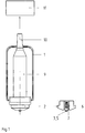
- the device for volume determination shown as an exemplary embodiment the cells of a printing roller by using a capacitive Measuring method consists of a basic device 1 with a Measuring head 2.
- the measuring head 2 is detachably connected to the basic device 1 (e.g. by screw connection), so that depending on the Conditions of use of the optimal measuring head 2 of the basic device 1 can be assigned.
- the measuring electrode 3 is in the direction of the one to be evaluated
- Printing roller 4 an electrically insulating protective layer system 5 assigned.
- the measuring head 2 also has a ground shield 6 and an active phase-synchronous screen 7. These components 6 and 7 shade the measuring electrode 3 from electrical interference fields from.
- the active screen 7 also largely homogenizes that electrical measuring field and dampens electrical stray fields at the edge the measuring electrode 3.
- the measuring electrode 3 is resiliently mounted in the measuring head 2. Thereby the measuring electrode 3 is always with when placed on the roller 4 a constant force is pressed onto the roller surface. As a result reproducible measurement parameters result simultaneously damage to the measuring electrode 3 is avoided.
- the size the measuring electrode 3 is advantageously chosen so that this electrode 3 covers a multiplicity of cups 8, which are consequently in a common measurement can be included. By inclusion the result of such a large number of wells 8 becomes essential more significant and leads to statistically reliable statements. Thus, it is excluded that the user by the Measurement of individual cells due to 8 very different measured values the possibly very different geometries of side by side Wells 8 receives. Systematic deviations, which are due to different roller diameters of the plane measuring electrode 3 result from a correction factor compensated, which is based on the known diameter of the Roll 4 results.
- sensor electronics 9 are integrated, with which the measuring capacity generated by the measuring head 2 is converted into a signal becomes.
- This, at the output of the sensor electronics 9 as a frequency Available signal is from the basic device 1 via a connection cable 10 passed to an evaluation and control electronics 11.
- This spatial separation of measured value acquisition and measured value evaluation offers the possibility of making the measuring system manageable To design a case measuring system. That on the roller surface basic device 1 with measuring head 2 is small and light, so measurements within printing presses are essential be relieved. In addition to this improved handling especially the short measuring time of just a few seconds advantageous.
- the measuring device forms an electrical system with the pressure roller to be measured and uses the electrical field as a measurement information carrier for determining the cell volume.
- a capacitor is formed by placing the measuring head 2 on the surface of the engraved roller 4, the electrodes of which act as the measuring electrode 3 and the surface of the roller 4.
- An electrical field is built up by applying an electrical voltage so that the capacitance of the measuring capacitor thus created can be determined.
- the protective layer system 5 the height of which is marked “S 0 " in the drawing, electrically isolates the measuring electrode 3 from the roller 4, so that no charge carrier exchange is possible between the two electrodes.
- the measuring capacitance consequently results from two partial capacitances connected in series.
- the first partial capacitance is determined by the geometric and electrical properties of the protective layer system 5 on the measuring electrode 3.
- the second partial capacity results from the air volume of the wells 8 to be measured in the pressure roller 4.
- the depth of the wells 8 is denoted by "S 1 ".
- the illustration shows an ideal cell geometry, which can hardly be achieved even by means of electromechanical engraving. If wells 8 of such exact design could be realized, the known optical measuring methods would suffice anyway.
- the first partial capacity is constant, so that the measured capacitance "C M" is dependent on the second partial capacity as the total capacity of the measuring capacitor. Since this second partial capacitance is determined by the volume of the wells 8, the total capacitance changes depending on the particular well contour present. If the scooping volume of the wells 8 changes, which corresponds to the air volume of the wells 8 at the time of the "colorless" test, the measuring capacity and consequently also the measured value change. Consequently, the proposed measuring method is actually suitable for obtaining a statement on the volume of the cups 8 configured in the pressure roller 4 on a non-optical principle. In addition to the evaluation of individual measured values and series of measurements and the comparison with target values and tolerance limits, special software also enables a statistical analysis of specified quantities of measured values.
- the proposed measuring method can also be used on such rolls, the metallic roll core of which is ceramic-coated.
- the measuring capacity is composed not only of the first and second partial capacities, but also of an additional third partial capacity, which is determined by the ceramic portion.
- the third partial capacitance can be taken into account in the measurement by entering the ceramic layer thickness “S K ”, the measurement of the ceramic layer 12 advantageously being carried out using a simple hand-held measuring device.
- the measurements allow, regardless of the particular Manufacturing technology of the rollers, statements about the volume the cup, for wear especially on anilox rollers, for determining screen tone values and for detecting Color residues.
Landscapes
- Physics & Mathematics (AREA)
- General Physics & Mathematics (AREA)
- Fluid Mechanics (AREA)
- Inking, Control Or Cleaning Of Printing Machines (AREA)
- Force Measurement Appropriate To Specific Purposes (AREA)
Applications Claiming Priority (2)
| Application Number | Priority Date | Filing Date | Title |
|---|---|---|---|
| DE19745104 | 1997-10-11 | ||
| DE1997145104 DE19745104C2 (de) | 1997-10-11 | 1997-10-11 | Vorrichtung zur Messung des Volumens von Näpfchen an Druckwalzen |
Publications (1)
| Publication Number | Publication Date |
|---|---|
| EP0908697A1 true EP0908697A1 (fr) | 1999-04-14 |
Family
ID=7845346
Family Applications (1)
| Application Number | Title | Priority Date | Filing Date |
|---|---|---|---|
| EP98119193A Withdrawn EP0908697A1 (fr) | 1997-10-11 | 1998-10-12 | Procédé et appareil pour la mesure du volume des cellules sur un rouleu d'impression |
Country Status (2)
| Country | Link |
|---|---|
| EP (1) | EP0908697A1 (fr) |
| DE (1) | DE19745104C2 (fr) |
Families Citing this family (1)
| Publication number | Priority date | Publication date | Assignee | Title |
|---|---|---|---|---|
| DE102009058845B4 (de) | 2009-12-18 | 2012-12-06 | Christof Tielemann | Verfahren zur Herstellung einer Druckwalze mit einer Laser-gravierten Oberfläche |
Citations (7)
| Publication number | Priority date | Publication date | Assignee | Title |
|---|---|---|---|---|
| CH291237A (de) * | 1950-02-10 | 1953-06-15 | Walter Dr Ing Zimmermann | Verfahren und Vorrichtung zur Messung der Rauhigkeit planbearbeiteter metallischer Oberflächen. |
| DE1253280B (de) * | 1965-09-22 | 1967-11-02 | Habra Werk Ott Kg | Verfahren und Vorrichtung zum Messen der AEtztiefe von Druckzylindern |
| DE1548354A1 (de) * | 1965-08-19 | 1970-02-12 | Alfred Wacker | Verfahren zur genauen Messung der Gravurtiefe in Helligkeitswerten unter 50% bei der Herstellung von gerasterten Metallklischees mit elektromechanischen Mitteln unter Verwendung der Methoden der Bildtelegraphie und Vorrichtung zur Ausuebung des Verfahrens |
| US3931570A (en) * | 1974-09-19 | 1976-01-06 | Gravure Research Institute, Inc. | Apparatus for measuring cell volume in a gravure printing surface |
| EP0448988A1 (fr) * | 1990-03-27 | 1991-10-02 | FIFE GmbH | Dispositif pour détecter sans contact la position d'une bande en mouvement |
| US5235851A (en) * | 1992-01-17 | 1993-08-17 | Pamarco Incorporated | Apparatus for the measurement of volumetric capacity of anilox rolls |
| EP0640812A2 (fr) * | 1993-08-25 | 1995-03-01 | Praxair S.T. Technology, Inc. | Procédé pour la mesure par fluorescence de la capacité volumétrique d'une surface gravée en cellules |
Family Cites Families (2)
| Publication number | Priority date | Publication date | Assignee | Title |
|---|---|---|---|---|
| DE3614646A1 (de) * | 1986-04-30 | 1987-11-05 | Grude Elektronik Gmbh | Verfahren zur vermessung von vertiefungen in oberflaechen, insbesondere des volumens von gravurnaepfchen in druckflaechen |
| US5315259A (en) * | 1992-05-26 | 1994-05-24 | Universities Research Association, Inc. | Omnidirectional capacitive probe for gauge of having a sensing tip formed as a substantially complete sphere |
-
1997
- 1997-10-11 DE DE1997145104 patent/DE19745104C2/de not_active Expired - Fee Related
-
1998
- 1998-10-12 EP EP98119193A patent/EP0908697A1/fr not_active Withdrawn
Patent Citations (7)
| Publication number | Priority date | Publication date | Assignee | Title |
|---|---|---|---|---|
| CH291237A (de) * | 1950-02-10 | 1953-06-15 | Walter Dr Ing Zimmermann | Verfahren und Vorrichtung zur Messung der Rauhigkeit planbearbeiteter metallischer Oberflächen. |
| DE1548354A1 (de) * | 1965-08-19 | 1970-02-12 | Alfred Wacker | Verfahren zur genauen Messung der Gravurtiefe in Helligkeitswerten unter 50% bei der Herstellung von gerasterten Metallklischees mit elektromechanischen Mitteln unter Verwendung der Methoden der Bildtelegraphie und Vorrichtung zur Ausuebung des Verfahrens |
| DE1253280B (de) * | 1965-09-22 | 1967-11-02 | Habra Werk Ott Kg | Verfahren und Vorrichtung zum Messen der AEtztiefe von Druckzylindern |
| US3931570A (en) * | 1974-09-19 | 1976-01-06 | Gravure Research Institute, Inc. | Apparatus for measuring cell volume in a gravure printing surface |
| EP0448988A1 (fr) * | 1990-03-27 | 1991-10-02 | FIFE GmbH | Dispositif pour détecter sans contact la position d'une bande en mouvement |
| US5235851A (en) * | 1992-01-17 | 1993-08-17 | Pamarco Incorporated | Apparatus for the measurement of volumetric capacity of anilox rolls |
| EP0640812A2 (fr) * | 1993-08-25 | 1995-03-01 | Praxair S.T. Technology, Inc. | Procédé pour la mesure par fluorescence de la capacité volumétrique d'une surface gravée en cellules |
Also Published As
| Publication number | Publication date |
|---|---|
| DE19745104A1 (de) | 1999-04-29 |
| DE19745104C2 (de) | 2001-10-04 |
Similar Documents
| Publication | Publication Date | Title |
|---|---|---|
| DE102007063627B4 (de) | Verfahren zur Bestimmung der Lage eines Laserstrahls relativ zu einer Öffnung, sowie Laserbearbeitungsmaschine | |
| DE4327712C2 (de) | Sensoranordnung und Verfahren zum Erfassen von Eigenschaften der Oberflächenschicht eines metallischen Targets | |
| DE602006000434T3 (de) | Druckplattenherstellungsgerät | |
| DE69119397T2 (de) | Härteprüfeinrichtung und verfahren zur messung der härte von metallischen werkstoffen | |
| DE2952825A1 (de) | Kapazitives und beruehrungsfrei arbeitendes messystem | |
| EP1225443A2 (fr) | Dispositif de détection de bavures | |
| DE3224980C2 (de) | Selbsttätig arbeitendes Zahnradprüfgerät | |
| WO1987007369A1 (fr) | Procede de mesurage de volume pour des creux de surface | |
| DE10023752B4 (de) | Verfahren und Vorrichtung zur Bestimmung zumindest eines bruchmechanischen Materialparameters eines Prüfkörpers | |
| DE19745104C2 (de) | Vorrichtung zur Messung des Volumens von Näpfchen an Druckwalzen | |
| DE3432701C1 (de) | Vorrichtung zur Messung der Druckbeistellung zwischen Zylindern einer Druckmaschine | |
| EP3525953B1 (fr) | Procédé d'ajustage d'un outil de formage à l'aide d'une matière de dressage | |
| EP0592878A2 (fr) | Procédé et dispositif de contrôle des cartes à pointes pour tester des circuits intégrés | |
| DE10101624A1 (de) | Anordnung zur Scharfeinstellung für Mikroskope | |
| DE10042715B4 (de) | Taststift und Verfahren zur Herstellung eines Taststiftes | |
| DE69511606T2 (de) | Vorrichtung zur Profilmessung einer ebenen Oberfläche | |
| DE2708417C2 (de) | Vorrichtung zum Messen einer Querdimension eines längsbewegten kontinuierlichen Gutes | |
| DE10232131C1 (de) | Vorrichtung und Verfahren zur Prüfung von Bohrungen oder Kanten in einem Meßgegenstand | |
| EP2052369B1 (fr) | Capteur et dispositif de contrôle d'un produit en feuille et procédé de translation de capteurs | |
| DE102006001799B4 (de) | Verfahren und Vorrichtung zur Erfassung von Drallstrukturen | |
| DE102018206232A1 (de) | Verfahren zum Detektieren einer Fehlstellung einer Schneidoptik einer Laserschneidmaschine, Auswerteeinrichtung und Laserschneidmaschine | |
| DE10233539A1 (de) | Verfahren und Vorrichtung zur Messung von Werkstückbohrungen | |
| DE102018133220A1 (de) | Konturerfassungsvorrichtung sowie deren Verwendung | |
| DE19708469C2 (de) | Verfahren zur Kalibrierung eines Graviersystems und Gravierverfahren | |
| DE3123635C2 (de) | Vorrichtung zur Prüfung der Maßhaltigkeit von Glasflaschen |
Legal Events
| Date | Code | Title | Description |
|---|---|---|---|
| PUAI | Public reference made under article 153(3) epc to a published international application that has entered the european phase |
Free format text: ORIGINAL CODE: 0009012 |
|
| AK | Designated contracting states |
Kind code of ref document: A1 Designated state(s): AT BE CH CY DE DK ES FI FR GB GR IE IT LI LU MC NL PT SE |
|
| AX | Request for extension of the european patent |
Free format text: AL;LT;LV;MK;RO;SI |
|
| RTI1 | Title (correction) | ||
| RAP3 | Party data changed (applicant data changed or rights of an application transferred) |
Owner name: MICROSPACE MESS- UND SENSORTECHNIK GMBH |
|
| K1C1 | Correction of patent application (title page) published |
Effective date: 19990414 |
|
| AKX | Designation fees paid | ||
| STAA | Information on the status of an ep patent application or granted ep patent |
Free format text: STATUS: THE APPLICATION IS DEEMED TO BE WITHDRAWN |
|
| 18D | Application deemed to be withdrawn |
Effective date: 19991015 |
|
| REG | Reference to a national code |
Ref country code: DE Ref legal event code: 8566 |