EP0908715A2 - Système d'évaluation des caractéristiques d'une fibre optique et moyen d'enregistrement, lisible par ordinateur, sur lequel le programme utilisé dans le système est enrégistré - Google Patents
Système d'évaluation des caractéristiques d'une fibre optique et moyen d'enregistrement, lisible par ordinateur, sur lequel le programme utilisé dans le système est enrégistré Download PDFInfo
- Publication number
- EP0908715A2 EP0908715A2 EP98118695A EP98118695A EP0908715A2 EP 0908715 A2 EP0908715 A2 EP 0908715A2 EP 98118695 A EP98118695 A EP 98118695A EP 98118695 A EP98118695 A EP 98118695A EP 0908715 A2 EP0908715 A2 EP 0908715A2
- Authority
- EP
- European Patent Office
- Prior art keywords
- characteristic data
- characteristic
- computer
- optical fiber
- reference point
- Prior art date
- Legal status (The legal status is an assumption and is not a legal conclusion. Google has not performed a legal analysis and makes no representation as to the accuracy of the status listed.)
- Granted
Links
- 239000013307 optical fiber Substances 0.000 title claims abstract description 179
- 238000011156 evaluation Methods 0.000 title claims description 71
- 238000004590 computer program Methods 0.000 title description 15
- 238000013500 data storage Methods 0.000 claims abstract description 8
- 230000003287 optical effect Effects 0.000 claims description 46
- 238000004519 manufacturing process Methods 0.000 claims description 7
- 238000000034 method Methods 0.000 claims description 3
- 230000006870 function Effects 0.000 description 34
- 230000005540 biological transmission Effects 0.000 description 23
- 239000003550 marker Substances 0.000 description 18
- 238000012545 processing Methods 0.000 description 10
- 238000010586 diagram Methods 0.000 description 6
- 238000012360 testing method Methods 0.000 description 6
- 239000000835 fiber Substances 0.000 description 4
- 238000004364 calculation method Methods 0.000 description 3
- 238000004891 communication Methods 0.000 description 3
- 238000012935 Averaging Methods 0.000 description 2
- 230000001747 exhibiting effect Effects 0.000 description 2
- 238000005259 measurement Methods 0.000 description 2
- 230000000694 effects Effects 0.000 description 1
- 239000004973 liquid crystal related substance Substances 0.000 description 1
- 239000002184 metal Substances 0.000 description 1
- 230000010287 polarization Effects 0.000 description 1
- 238000005070 sampling Methods 0.000 description 1
- 230000008054 signal transmission Effects 0.000 description 1
Images




Classifications
-
- G—PHYSICS
- G01—MEASURING; TESTING
- G01M—TESTING STATIC OR DYNAMIC BALANCE OF MACHINES OR STRUCTURES; TESTING OF STRUCTURES OR APPARATUS, NOT OTHERWISE PROVIDED FOR
- G01M11/00—Testing of optical apparatus; Testing structures by optical methods not otherwise provided for
- G01M11/30—Testing of optical devices, constituted by fibre optics or optical waveguides
- G01M11/31—Testing of optical devices, constituted by fibre optics or optical waveguides with a light emitter and a light receiver being disposed at the same side of a fibre or waveguide end-face, e.g. reflectometers
- G01M11/3109—Reflectometers detecting the back-scattered light in the time-domain, e.g. OTDR
- G01M11/3136—Reflectometers detecting the back-scattered light in the time-domain, e.g. OTDR for testing of multiple fibers
Definitions
- the present invention relates to an optical fiber characteristic evaluation system for evaluating the transmission characteristics of many optical fibers forming optical transmission lines in a communication system or the like, and a computer-readable recording medium on which a computer program used for the system is recorded.
- optical fibers have been widely used as signal transmission lines in communication systems and the like in place of conventional metal lines.
- one optical fiber includes a plurality of optical fibers connected in series.
- optical fibers are tested by using an optical time-domain reflectometer (OTDR) like the one shown in FIG. 10.
- OTDR optical time-domain reflectometer
- an optical pulse from an optical pulse generator 10 is input to one end of one of optical fibers 2 1 to 2 n of an optical multi-fiber cable 1 through a directional coupler 11 and an optical path switch 12, and a photodetector 13 detects the intensity of light (backward scattered light or reflected light) returning to the one end side of the optical fiber.
- An A/D converter 14 then converts the photodetection signal output from the photodetector 13 into a data signal, and inputs it to a signal processor 15.
- the signal processor 15 processes a series of data signals until a predetermined period of time elapses after the incident timing of the optical pulse, and stores the distance versus received light intensity characteristic data in a characteristic data memory 16.
- the optical path switch 12 is switched to connect another optical fiber to the directional coupler 11, thus storing the characteristic data of the optical fibers 2 1 to 2 n in the characteristic data memory 16.
- the transmission characteristics of each optical fiber are evaluated as follows.
- the characteristic data stored in the characteristic data memory 16 is selectively output to an image display unit or printer (not shown) to display a waveform on the coordinate plane defined by the distance axis and the received light intensity axis, as shown in FIG. 11. Variations in attenuation value and the presence/absence of a disconnection or the like are checked from the slope of the displayed waveform, local level changes, and the like.
- the characteristic data stored in the characteristic data memory 16 must be displayed on the same coordinate plane and evaluated.
- the characteristic data obtained from optical fibers having the same characteristics vary due to variations in the wavelength of an optical pulse and variations in connection loss in the optical path switch 12.
- the waveforms of the characteristic data obtained by this OTDR are displayed on the same coordinate plane, the displayed waveforms greatly shift from each other in the vertical direction than the variations of the characteristic data, even though the optical fibers have almost the same characteristics. For this reason, it is very difficult to detect the overall characteristics of the cable and evaluate the characteristics of one optical fiber in contrast to the characteristics of the overall transmission line.
- one transmission line is made by connecting a plurality of optical fibers each having a length of several km.
- connection losses are accumulated in the transmission line having a plurality of connection points, if using optical fibers having the same characteristics, the characteristics of the overall transmission line differ from every transmission lines.
- the characteristic data of the near portion of the certain connection point greatly varies due to accumulating variations in the connection loss and accumulated variations in connection loss in the optical path switch 12.
- the OTDR can acquire the characteristics of several ten to several thousand optical fibers. This makes it more difficult to perform evaluation.
- an optical fiber characteristic evaluation apparatus comprising:
- an optical fiber characteristic evaluation method comprising the steps of:
- an article of manufacture comprising:
- an article of manufacture comprising:
- an article of manufacture comprising:
- the first optical fiber characteristic evaluation apparatus of the present invention comprises:
- the second optical fiber characteristic evaluation apparatus of the present invention is characterized in that in the first optical fiber characteristic evaluation apparatus, the reference point designating means includes a reference characteristic data designating means (38) for designating arbitrary characteristic data, of the plurality of characteristic data, as reference characteristic data, and a distance designating means (39) for designating an arbitrary distance position, and designates a coordinate point, as the reference point, determined by the distance position designated by the distance designating means and the characteristic value of the reference characteristic data at the distance position, and the waveform display control means displays the waveform of the characteristic data designated by the reference characteristic data designating means in distinction from the waveforms of other characteristic data.
- the reference point designating means includes a reference characteristic data designating means (38) for designating arbitrary characteristic data, of the plurality of characteristic data, as reference characteristic data, and a distance designating means (39) for designating an arbitrary distance position, and designates a coordinate point, as the reference point, determined by the distance position designated by the distance designating means and the characteristic value of the reference characteristic data at the distance position, and
- a program for allowing a computer having an output unit for displaying waveforms to have the following functions is recorded:
- a program for allowing a computer having an output unit for displaying waveforms to have the following functions is recorded:
- an optical pulse output from an optical pulse generator 21 is guided to an optical path switch 23 through a directional coupler 22. Then, the optical pulse is selectively input to one end of one of optical fibers 2 1 to 2 n of an optical multi-fiber cable 1 connected to the optical path switch 23.
- the light returning from one of the optical fibers 2 1 to 2 n to which the optical pulse was incident is input to a photodetector 24 through the directional coupler 22.
- the photodetector 24 outputs a photodetection signal whose level changes in accordance with a change in intensity as one of the characteristic values of the return light.
- This photodetection signal is converted into a digital data signal by an A/D converter 25.
- a data processor 26 then performs averaging processing for this signal.
- the resultant data is stored in a detachable memory card 27 as characteristic data indicating a change in distance versus received light intensity of one optical fiber.
- a test controller 28 causes the optical pulse generator 21 to output an optical pulse to the same optical fiber a number of times required for the above averaging processing.
- the test controller 28 then stores the resultant characteristic data in the memory card 27, together with a corresponding piece of information F 1 to F n (pieces of file name information or the like) which specifies the optical fiber having the corresponding characteristic, and switches the optical path switch 23 to the optical fiber to be tested next in a predetermined order.
- distance versus received light intensity characteristic data D 1 to D n of the optical fibers 2 1 to 2 n are stored in the memory card 27, together with the information F 1 to F n of the respective optical fibers.
- This memory card 27 is removed from the OTDR 20 and inserted into the optical fiber characteristic evaluation apparatus shown in FIG. 1A.
- This arrangement is used to allow the measurement data obtained by the OTDR 20 at the site of an optical fiber cable to be analyzed by a computer installed in a place other than the site.
- this optical fiber characteristic evaluation apparatus is made up of a personal computer PC including a tower controller 30 as a personal computer body, an operation unit 31 constituted by a keyboard and a mouse, and an image display unit 32 such as a CRT or liquid crystal display serving as an output unit, and a floppy disk FD that is inserted into the personal computer and serves as a computer-readable recording medium on which a computer program like the one shown in FIGS. 1C to 1E is recorded.
- a personal computer PC including a tower controller 30 as a personal computer body, an operation unit 31 constituted by a keyboard and a mouse, and an image display unit 32 such as a CRT or liquid crystal display serving as an output unit, and a floppy disk FD that is inserted into the personal computer and serves as a computer-readable recording medium on which a computer program like the one shown in FIGS. 1C to 1E is recorded.
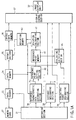
- FIG. 1A is a block diagram showing the functions executed by the program loaded from the floppy disk FD (other media such as a magnetooptical disk, a CD-ROM, and IC memory card can also be used) as a computer-readable recording medium into the personal computer PC.
- FD floppy disk
- other media such as a magnetooptical disk, a CD-ROM, and IC memory card can also be used
- IC memory card can also be used
- FIG. 1A is a block diagram showing the functions executed by the program loaded from the floppy disk FD (other media such as a magnetooptical disk, a CD-ROM, and IC memory card can also be used) as a computer-readable recording medium into the personal computer PC.
- these functions can be implemented by hardware.
- a data reader 33 reads out data from the memory card 27 and stores the data in a data memory 34 serving as a characteristic data storage means of this embodiment (steps S1 and S11).
- An offset section 35 subtracts deviations d 1 to d n corresponding to the respective optical fibers and stored in a deviation memory 43 (to be described later) from the characteristic data D 1 to D n stored in the data memory 34, and stores the subtraction results as offset characteristic data D 1 ' to D n ' in an offset data memory 36 (steps S3 and S15).
- the first offset characteristic data D 1 ' to D n ' stored in the offset data memory 36 are identical to the characteristic data D 1 to D n read out from the memory card 27.
- a display control section 37 serves as a waveform display means in this embodiment.
- the display control section 37 displays an orthogonal coordinate plane on the screen of the image display unit 32, with the abscissa and ordinate respectively representing distance and received light intensity.
- the display control section 37 displays the waveforms of a plurality of offset characteristic data stored in the offset data memory 36 on this coordinate plane (steps S4 and S16).
- this display control section 37 displays the waveform of the characteristic data corresponding to the information selected/designated by a reference characteristic data designating section 38 (to be described later) in a color different from that of the waveforms of the remaining characteristic data.
- the reference characteristic data designating section 38 displays, through the display control section 37, a button ("REF. FILE" in FIGS. 3 to 9 to be described later) for displaying the pieces of information F 1 to F n corresponding to the respective characteristic data on the screen of the image display unit 32, and also allows the operator to select/designate one of the pieces of information which corresponds to reference characteristic data upon cursor operation by displaying all the pieces of information F 1 to F n stored in the data reader 33 on the image display unit 32 when this button is operated with the operation unit 31 (step S12).
- a button (“REF. FILE" in FIGS. 3 to 9 to be described later
- a distance designating section 39 displays, through the display control section 37, a button ("REF. POSIT" in FIGS. 3 to 9 to be described later) for displaying a reference marker line on the screen of the image display unit 32.
- the distance designating section 39 displays the reference marker line in a state movable along the distance axis on the screen, and also allows the operator to designate a distance coordinate a of the reference marker line by confirming operation using the operation unit 31.
- a reference point setting section 40 stores/sets a coordinate point (a, D x (a)] as a reference point in a reference point memory 41, which point is determined by a distance a designated by the distance designating section 39 and a received light intensity D x (a) at the distance a of reference characteristic data D x corresponding to information F x selected/designated by the reference characteristic data designating section 38 (step S2).
- a deviation calculating section 42 reads out received light intensities D 1 (a), D 2 (a), ..., D n (a) of the characteristic data stored in the data memory 34 at the distance coordinates a set in the reference point memory 41, and subtracts the received light intensity coordinate D x (a) set in the reference point memory 41 from each of the received light intensities D 1 (a), D 2 (a), ..., D n (a) to obtain the subtraction results as the deviations d 1 to d n corresponding to the respective optical fibers.
- the deviations d 1 to d n corresponding to the respective optical fibers are stored in the deviation memory 43 (steps S3 and S15).
- An evaluation point designating section 44 displays a button ("MES. POSIT" in FIGS. 3 to 9 (to be described later) for displaying an evaluation marker line on the screen of the image display unit 32, similar to the distance designating section 39 described above.
- the evaluation point designating section 44 displays the evaluation marker line in a state movable along the distance axis, and allows the operator to designate distance coordinates b of the evaluation marker line by confirming operation using the operation unit 31.
- An evaluating/calculating section 45 subtracts a received light intensity D x (b) at a distance b designated by the evaluation point designating section 44 from the received light intensity D x (a) of the reference point on the reference characteristic data D x to obtain the attenuation value of an optical fiber 2 x from the point at the distance a to the point at the distance b .
- the evaluating/calculating section 45 also divides this attenuation value by a distance difference (b - a) to obtain an attenuation value per unit distance (attenuation ratio).
- the calculation results obtained by the evaluating/calculating section 45 are displayed on the screen of the image display unit 32 through the display control section 37.
- This attenuation ratio corresponds to the slope of the displayed reference characteristic data.
- the memory card 27 in which the characteristic data D 1 to D n of the optical fibers 2 1 to 2 n tested by the OTDR 20 and the pieces of information F 1 to F n are stored in advance is inserted into this optical fiber characteristic evaluation apparatus.
- the data in the memory card 27 is stored in the data memory 34 (steps S1 and S11).
- the characteristic data D 1 to D n stored in the data memory 34 are stored in the offset data memory 36 through the offset section 35.
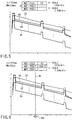
- the waveforms of the characteristic data of the respective optical fibers are displayed in the same color on the screen of the image display unit 32 through the display control section 37, with the displayed waveforms varying vertically owing to variations in the characteristics of the directional coupler 22 of the OTDR 20 and fluctuations in the wavelengths of optical pulses.
- the pieces of information F 1 to F n stored in the data memory 34 are displayed as a list on the screen of the image display unit 32 in the form of a table, for example, as shown in FIG. 4.
- the color of the waveform (indicated by the thick line in FIG. 5) of the characteristic data D 2 corresponding to the information F 2 is changed to a color different from that of the remaining waveforms (step S18).
- the waveform of the characteristic data D 2 is displayed in a different color (e.g., green), and the waveform of the reference characteristic data is re-displayed in a different color at the forefront so as not to be covered with other waveforms (steps S17 and S18).
- a movable reference marker line Mr is displayed at a predetermined position.
- the reference point coordinates based on the distance coordinate a of the reference marker line Mr and the received light intensity coordinate D 2 (a) of the characteristic data D 2 at the distance a are set in the reference point memory 41 (steps S2 and S14).
- the results obtained by the deviation calculating section 42 by subtracting the received light intensity D 2 (a) from the received light intensities D 1 (a), D 2 (a), .., D n (a) of the respective characteristic data at the distance a stored in the data memory 34 are stored as the deviations d 1 to d n in the deviation memory 43 (steps S3 and S15).
- the deviation d 2 of the optical fiber 22 which is designated as reference characteristic data is 0.
- the waveforms of all the characteristic data displayed on the screen of the image display unit 32 pass through a reference point on the characteristic data serving as a reference, as shown in FIG. 7.
- the waveforms of characteristic data displayed on the screen of the image display unit 32 therefore, the waveforms of characteristic data whose transmission characteristics are almost the same as those of the reference characteristic data are superimposed on the waveform of the reference characteristic data (steps S4 and S16) as shown in FIG. 7.
- the waveforms of characteristic data different in attenuation ratio or the like from the reference characteristic data are displayed apart from the reference waveform.
- a movable evaluation marker line Mm is displayed on the screen of the image display unit 32, as shown in FIG. 8.
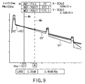
- the evaluation point designating section 44 obtains a received light intensity coordinate D 2 (b) of the characteristic data D 2 at a distance coordinate b of the evaluation marker line Mm, and also calculates the attenuation value and ratio between the point at the distance a and the point at the distance b .
- the attenuation value and ratio between the point at the distance a and the point at the distance b are displayed, for example, like "LOSS 0.20 dB, 0.40 dB/Km" on the screen of the image display unit 32 through the display control section 37, as shown in FIG. 9.
- the positions of the reference marker line Mr and the evaluation marker line Mm can be changed by operating the button "REF. POSIT” and the button “MES. POSIT” or directly operating the reference marker line Mr and the evaluation marker line Mm with the mouse cursor.
- the characteristic data read out from the memory card 27 are stored in the offset data memory 36 as well as the data memory 34, and the waveforms of the characteristic data without offset processing are displayed on the screen of the image display unit 32.
- the information F x and the distance a corresponding to reference characteristic data may be designated to cause the deviation calculating section 42 to calculate the deviations from the reference point in units of characteristic data.
- the characteristic data may be stored in the offset data memory 36 after the offset section 35 performs offset processing for the characteristic data in the data memory 34 by using the calculated deviations.
- the waveforms of the characteristic data having undergone offset processing can be displayed from the beginning.
- the displayed waveforms can be restored to the waveforms of the initial characteristic data before offset processing.
- the optical fiber characteristic evaluation apparatus of this embodiment performs offset processing for the characteristic data of optical fibers, which are obtained in the presence of variations in optical pulse wavelength and variations in the loss of the optical path switch, so as to display the waveforms of the respective characteristic data such that the waveforms pass through a reference point.
- the waveforms of characteristic data exhibiting similar transmission characteristics are superimposed on each other, whereas the waveforms of characteristic data exhibiting different transmission characteristics are displayed apart from each other. This allows the operator to accurately grasp the overall characteristics of the optical fiber cable 1.
- the optical fiber characteristic evaluation apparatus of this embodiment displays the waveform of characteristic data designated as a reference in a color different from that of the remaining waveforms so as to be identified.
- the characteristic of one optical fiber can be easily recognized among the characteristics of the overall optical fiber cable. This facilitates evaluation of the optical fiber.
- the above embodiment uses the image display unit 32 as an output unit for displaying the waveforms of characteristic data.
- a printer or plotter may be used to print out the waveforms of characteristic data.
- a plurality of characteristic data are read out from the memory card 27 and input to the apparatus.
- characteristic data may be read out from a floppy disk, a detachable hard disk, or a magnetooptical disk and input to the apparatus.
- a communication unit may be placed between this optical fiber characteristic evaluation apparatus and an OTDR 20 to allow the optical fiber characteristic evaluation apparatus to receive a plurality of characteristic data transmitted from the OTDR 20.
- the characteristic data may be input to the apparatus in this manner.
- the data stored in the memory card 27 is temporarily loaded into the data memory 34 to be subjected to offset processing in the offset section 35.
- an offset section 35 may directly perform offset processing for the data read out from a memory card 27 and may write the resultant data in an offset data memory 36.
- the memory card 27 itself serves as a characteristic data storage means.
- the optical fiber characteristic evaluation apparatus of the above embodiment is formed independently of the OTDR 20 to allow the characteristic data obtained at the site of optical fibers to be evaluated in a different place.
- optical fiber characteristic evaluation apparatus may be integrally formed with the OTDR 20.
- a storage medium used to store characteristic data need not be detachable.
- the coordinates of a reference point are set on arbitrarily selected characteristic data.
- the coordinates of an arbitrary reference point may be input by operating an operation unit 31 regardless of characteristic data, and the differences between the received light intensities of the respective characteristic data at the distance position of the set reference point and the received light intensity of the reference point may be calculated. Then, the respective characteristic data may be offset in the received light intensity axis direction by the amounts corresponding to the calculated differences so as to display the waveforms of the characteristic data such that all the waveforms pass through the reference point.
- the waveform of the arbitrarily designated characteristic data is displayed in a color different from that of the waveforms of the remaining characteristic data, the characteristics of the specific optical fiber among the overall characteristics of the optical fibers can be easily identified.
- deviations are calculated in units of optical fibers from the received light intensities D 1 (a), D 2 (a), ..., D n (a) of the respective characteristic data at the designated distance a .
- the received light intensities of the characteristic data corresponding to an arbitrarily set distance a may not be obtained.
- the received light intensities nearest to the point at the designated distance a may be used, or the average of a plurality of received light intensities near the point at the distance a may be obtained for each characteristic data, and the differences between the respective averages and the received light intensity of the reference point may be calculated to perform offset processing (steps S13, S14, and S15).
- the characteristic data of the distance versus received light intensities obtained by detecting the intensities of light beams returning from optical fibers as characteristic values are calculated.
- the present invention is not limited to this.
- the present invention can be applied to evaluation of characteristic data indicating changes in distance versus characteristic value which are obtained by detecting the angles of planes of polarization of returning light beams, the frequencies or the like of sideband light beams which are produced by the Doppler effect, or the like as characteristic values.
- the optical fiber characteristic evaluation apparatus of the present invention obtains the differences between characteristic data of the reference point arbitrarily designated by the reference point designating means and a plurality of characteristic data at the distance value of this reference point, and offsets the characteristic values of the characteristic data by the amounts corresponding to the differences, thereby displaying the waveforms of the plurality of characteristic data such that the waveforms pass through the reference point on the orthogonal coordinate plane defined by the distance axis and the characteristic value axis.
- the optical fiber characteristic evaluation apparatus of the present invention therefore, even with the characteristic data of a plurality of optical fibers which are obtained in the presence of variations in optical pulse wavelength, variations in the loss of the optical path switch, and the like, the overall characteristics of the optical fibers can be accurately detected.
- the optical fiber characteristic evaluation apparatus of the present invention designates characteristic data as a reference and a reference point on the characteristic data, and displays the waveform of the reference characteristic data such that the waveform can be discriminated from the remaining waveforms.
- optical fiber characteristic evaluation apparatus of the present invention therefore, a specific optical fiber of a plurality of optical fibers can be easily evaluated.
- an optical fiber characteristic evaluation apparatus which can solve the above problems in the prior art, and can easily detect the overall characteristics of a cable and evaluate the characteristics of one optical fiber in all overall transmission lines.
- an optical fiber characteristic evaluation method which can solve the above problems in the prior art, and can easily detect the overall characteristics of a cable and evaluate the characteristics of one optical fiber in contrast to characteristics of the overall transmission line.
- a computer-readable recording medium on which a computer program is recorded which is used for an optical fiber characteristic evaluation system which can solve the above problems in the prior art, and can easily detect the overall characteristics of a cable and evaluate the characteristics of one optical fiber in contrast to characteristics of the overall transmission line.
Landscapes
- Physics & Mathematics (AREA)
- Optics & Photonics (AREA)
- Chemical & Material Sciences (AREA)
- Analytical Chemistry (AREA)
- General Physics & Mathematics (AREA)
- Testing Of Optical Devices Or Fibers (AREA)
Applications Claiming Priority (3)
| Application Number | Priority Date | Filing Date | Title |
|---|---|---|---|
| JP29351397A JP3292982B2 (ja) | 1997-10-09 | 1997-10-09 | 光ファイバ特性評価装置及びプログラムを記録した媒体 |
| JP293513/97 | 1997-10-09 | ||
| JP29351397 | 1997-10-09 |
Publications (3)
| Publication Number | Publication Date |
|---|---|
| EP0908715A2 true EP0908715A2 (fr) | 1999-04-14 |
| EP0908715A3 EP0908715A3 (fr) | 2000-01-05 |
| EP0908715B1 EP0908715B1 (fr) | 2004-03-17 |
Family
ID=17795719
Family Applications (1)
| Application Number | Title | Priority Date | Filing Date |
|---|---|---|---|
| EP98118695A Expired - Lifetime EP0908715B1 (fr) | 1997-10-09 | 1998-10-02 | Système d'évaluation des caractéristiques d'une fibre optique et moyen d'enregistrement, lisible par ordinateur, sur lequel le programme utilisé dans le système est enregistré |
Country Status (4)
| Country | Link |
|---|---|
| US (1) | US6259993B1 (fr) |
| EP (1) | EP0908715B1 (fr) |
| JP (1) | JP3292982B2 (fr) |
| DE (1) | DE69822392T2 (fr) |
Cited By (3)
| Publication number | Priority date | Publication date | Assignee | Title |
|---|---|---|---|---|
| US6678041B2 (en) | 2000-07-10 | 2004-01-13 | Advantest Corporation | Optical characteristic measuring apparatus, the method thereof and recording medium |
| WO2012087205A1 (fr) * | 2010-12-22 | 2012-06-28 | Telefonaktiebolaget Lm Ericsson (Publ) | Analyse de trace otdr dans des systèmes pon |
| CN104395737A (zh) * | 2012-05-29 | 2015-03-04 | Afl电信公司 | 用于识别多芯光缆中的光纤顺序的系统和方法 |
Families Citing this family (13)
| Publication number | Priority date | Publication date | Assignee | Title |
|---|---|---|---|---|
| SE514745C2 (sv) * | 1999-06-18 | 2001-04-09 | Samba Sensors Ab | Förfarande och anordning för böjkompensation vid intensitetsbaserade optiska mätsystem |
| US20090027659A1 (en) * | 1999-06-18 | 2009-01-29 | Sambra Sensors Ab | Measuring system for measuring a physical parameter influencing a sensor element |
| US6411919B1 (en) * | 1999-09-27 | 2002-06-25 | General Electric Company | Method and apparatus for generating cable occupancy volumes |
| US6570592B1 (en) * | 1999-10-29 | 2003-05-27 | Agilent Technologies, Inc. | System and method for specifying trigger conditions of a signal measurement system using graphical elements on a graphical user interface |
| US6643436B2 (en) * | 2000-12-14 | 2003-11-04 | Radiodetection Limited | Identifying fibers of fiber optic cables |
| CA2644644A1 (fr) * | 2005-03-01 | 2006-09-08 | Avihu Nachmani | Procede de montage d'une carte a circuits imprimes |
| JP2007033255A (ja) * | 2005-07-27 | 2007-02-08 | Chugoku Electric Power Co Inc:The | 光ファイバーの検査システム |
| WO2007088976A1 (fr) | 2006-02-03 | 2007-08-09 | Fujikura Ltd. | Dispositif et procede de surveillance du trajet d'un faisceau lumineux |
| JP4864752B2 (ja) * | 2006-10-26 | 2012-02-01 | 株式会社フジクラ | 光伝送線路監視装置、光伝送線路監視方法、及び監視プログラム |
| JP2016057119A (ja) * | 2014-09-08 | 2016-04-21 | 横河電機株式会社 | 光パルス試験器 |
| DE102015113581B4 (de) | 2015-08-17 | 2021-02-04 | Aiq Dienstleistungen Ug (Haftungsbeschränkt) | Fasermessung mit Impulsformung |
| US10996138B2 (en) * | 2019-08-30 | 2021-05-04 | Viavi Solutions Inc. | Parallel optics based optical time domain reflectometer acquisition |
| CN116054931B (zh) * | 2023-02-21 | 2026-03-27 | 桂林聚联科技有限公司 | 一种光纤测量数据的补偿方法、装置、设备和存储介质 |
Family Cites Families (4)
| Publication number | Priority date | Publication date | Assignee | Title |
|---|---|---|---|---|
| DE4411407A1 (de) | 1994-03-31 | 1995-10-05 | Siemens Ag | Verfahren und Einrichtung zum Bestimmen von Dämpfungsänderungen bei einem Lichtwellenleiter |
| US5528356A (en) | 1995-03-20 | 1996-06-18 | Tektronix, Inc. | Apparatus and method for displaying multiple sample spacing waveform segments |
| JP3401376B2 (ja) * | 1995-10-26 | 2003-04-28 | 独立行政法人産業技術総合研究所 | 散乱物体の光学定数決定法 |
| US5963313A (en) * | 1998-05-15 | 1999-10-05 | Tektronix, Inc. | Optical time domain reflectometer with bandwidth correction |
-
1997
- 1997-10-09 JP JP29351397A patent/JP3292982B2/ja not_active Expired - Fee Related
-
1998
- 1998-09-25 US US09/160,603 patent/US6259993B1/en not_active Expired - Fee Related
- 1998-10-02 DE DE69822392T patent/DE69822392T2/de not_active Expired - Lifetime
- 1998-10-02 EP EP98118695A patent/EP0908715B1/fr not_active Expired - Lifetime
Cited By (6)
| Publication number | Priority date | Publication date | Assignee | Title |
|---|---|---|---|---|
| US6678041B2 (en) | 2000-07-10 | 2004-01-13 | Advantest Corporation | Optical characteristic measuring apparatus, the method thereof and recording medium |
| WO2012087205A1 (fr) * | 2010-12-22 | 2012-06-28 | Telefonaktiebolaget Lm Ericsson (Publ) | Analyse de trace otdr dans des systèmes pon |
| US8724102B2 (en) | 2010-12-22 | 2014-05-13 | Telefonaktièbolaget LM Ericsson (publ) | Optical time domain reflectometry (OTDR) trace analysis in PON systems |
| CN104395737A (zh) * | 2012-05-29 | 2015-03-04 | Afl电信公司 | 用于识别多芯光缆中的光纤顺序的系统和方法 |
| EP2852829A4 (fr) * | 2012-05-29 | 2016-01-27 | Afl Telecommunications Llc | Système et procédé pour identifier une séquence de fibres dans un câble optique à fibres multiples |
| US9435713B2 (en) | 2012-05-29 | 2016-09-06 | Afl Telecommunications Llc | System and method for identifying fiber sequence in a multi-fiber optical cable |
Also Published As
| Publication number | Publication date |
|---|---|
| DE69822392D1 (de) | 2004-04-22 |
| EP0908715B1 (fr) | 2004-03-17 |
| JP3292982B2 (ja) | 2002-06-17 |
| US6259993B1 (en) | 2001-07-10 |
| JPH11119027A (ja) | 1999-04-30 |
| DE69822392T2 (de) | 2004-12-23 |
| EP0908715A3 (fr) | 2000-01-05 |
Similar Documents
| Publication | Publication Date | Title |
|---|---|---|
| EP0908715B1 (fr) | Système d'évaluation des caractéristiques d'une fibre optique et moyen d'enregistrement, lisible par ordinateur, sur lequel le programme utilisé dans le système est enregistré | |
| JP2794172B2 (ja) | オプティカル・タイム・ドメイン・リフレクトメータ及び波形表示方法 | |
| US10014935B2 (en) | Multiple-acquisition OTDR method and device | |
| US6195614B1 (en) | Method of characterizing events in acquired waveform data from a metallic transmission cable | |
| JP2001074598A (ja) | 光パルス試験装置 | |
| US6310702B1 (en) | Testing device for multistage multi-branch optical network | |
| EP0318043B1 (fr) | OTDR avec fonction de mesure automatique des défauts de fibre optique | |
| EP0882993B1 (fr) | Appareil pour obtenir des données de forme d'onde d'un câble de transmission métallique | |
| EP0854360A1 (fr) | Appareil de controle de fibres optiques faisant appel a un reflectometre optique temporel et procede de controle | |
| US7411666B2 (en) | Optical time domain reflectometry system at different wavelengths | |
| US5373356A (en) | Method and apparatus for identifying echoes detected by an optical time-domain reflectometer | |
| JP2008136159A (ja) | 光伝送線路監視装置、光伝送線路監視方法、及び監視プログラム | |
| EP0869631A2 (fr) | Méthode de contrÔle de fibre optique | |
| EP0468412B1 (fr) | Procédé et dispositif d'essai de fibres optiques | |
| JP2011164074A (ja) | 光ケーブル敷設環境測定方法、光ケーブル敷設環境測定装置及び光ケーブル敷設環境測定システム | |
| US5668627A (en) | Optical line testing device and method for automatically and efficiently measuring properties of the optical line | |
| US20060256319A1 (en) | Determination of an optical property of a DUT by OTDR measurement | |
| JPH11119028A (ja) | 光ファイバ特性評価装置及びプログラムを記録した媒体 | |
| JPH10332530A (ja) | Otdr装置 | |
| CA2027448C (fr) | Ameliorations de reflectometres optiques temporels | |
| JP2010091521A (ja) | 光パルス試験器 | |
| JPH0331213B2 (fr) | ||
| JP6370845B2 (ja) | 測定システム | |
| JPH0868722A (ja) | 光線路特性の自動解析方法 | |
| JPH1056433A (ja) | 光パルス試験装置及び方法 |
Legal Events
| Date | Code | Title | Description |
|---|---|---|---|
| PUAI | Public reference made under article 153(3) epc to a published international application that has entered the european phase |
Free format text: ORIGINAL CODE: 0009012 |
|
| 17P | Request for examination filed |
Effective date: 19981002 |
|
| AK | Designated contracting states |
Kind code of ref document: A2 Designated state(s): DE FR GB |
|
| AX | Request for extension of the european patent |
Free format text: AL;LT;LV;MK;RO;SI |
|
| PUAL | Search report despatched |
Free format text: ORIGINAL CODE: 0009013 |
|
| AK | Designated contracting states |
Kind code of ref document: A3 Designated state(s): AT BE CH CY DE DK ES FI FR GB GR IE IT LI LU MC NL PT SE |
|
| AX | Request for extension of the european patent |
Free format text: AL;LT;LV;MK;RO;SI |
|
| AKX | Designation fees paid |
Free format text: DE FR GB |
|
| GRAP | Despatch of communication of intention to grant a patent |
Free format text: ORIGINAL CODE: EPIDOSNIGR1 |
|
| GRAS | Grant fee paid |
Free format text: ORIGINAL CODE: EPIDOSNIGR3 |
|
| GRAA | (expected) grant |
Free format text: ORIGINAL CODE: 0009210 |
|
| AK | Designated contracting states |
Kind code of ref document: B1 Designated state(s): DE FR GB |
|
| REG | Reference to a national code |
Ref country code: GB Ref legal event code: FG4D |
|
| REF | Corresponds to: |
Ref document number: 69822392 Country of ref document: DE Date of ref document: 20040422 Kind code of ref document: P |
|
| ET | Fr: translation filed | ||
| PLBE | No opposition filed within time limit |
Free format text: ORIGINAL CODE: 0009261 |
|
| STAA | Information on the status of an ep patent application or granted ep patent |
Free format text: STATUS: NO OPPOSITION FILED WITHIN TIME LIMIT |
|
| 26N | No opposition filed |
Effective date: 20041220 |
|
| PGFP | Annual fee paid to national office [announced via postgrant information from national office to epo] |
Ref country code: GB Payment date: 20120926 Year of fee payment: 15 |
|
| PGFP | Annual fee paid to national office [announced via postgrant information from national office to epo] |
Ref country code: FR Payment date: 20121018 Year of fee payment: 15 Ref country code: DE Payment date: 20120927 Year of fee payment: 15 |
|
| GBPC | Gb: european patent ceased through non-payment of renewal fee |
Effective date: 20131002 |
|
| REG | Reference to a national code |
Ref country code: DE Ref legal event code: R119 Ref document number: 69822392 Country of ref document: DE Effective date: 20140501 |
|
| PG25 | Lapsed in a contracting state [announced via postgrant information from national office to epo] |
Ref country code: GB Free format text: LAPSE BECAUSE OF NON-PAYMENT OF DUE FEES Effective date: 20131002 |
|
| REG | Reference to a national code |
Ref country code: FR Ref legal event code: ST Effective date: 20140630 |
|
| PG25 | Lapsed in a contracting state [announced via postgrant information from national office to epo] |
Ref country code: DE Free format text: LAPSE BECAUSE OF NON-PAYMENT OF DUE FEES Effective date: 20140501 Ref country code: FR Free format text: LAPSE BECAUSE OF NON-PAYMENT OF DUE FEES Effective date: 20131031 |