EP0908729B1 - Lager mit integriertem Sensor in Lagerbuchse - Google Patents
Lager mit integriertem Sensor in Lagerbuchse Download PDFInfo
- Publication number
- EP0908729B1 EP0908729B1 EP98402516A EP98402516A EP0908729B1 EP 0908729 B1 EP0908729 B1 EP 0908729B1 EP 98402516 A EP98402516 A EP 98402516A EP 98402516 A EP98402516 A EP 98402516A EP 0908729 B1 EP0908729 B1 EP 0908729B1
- Authority
- EP
- European Patent Office
- Prior art keywords
- self
- housed
- housing
- sensor
- bearing according
- Prior art date
- Legal status (The legal status is an assumption and is not a legal conclusion. Google has not performed a legal analysis and makes no representation as to the accuracy of the status listed.)
- Expired - Lifetime
Links
- 230000001681 protective effect Effects 0.000 claims description 20
- 239000004020 conductor Substances 0.000 claims description 14
- 239000002184 metal Substances 0.000 claims description 6
- 229910052751 metal Inorganic materials 0.000 claims description 6
- 230000005540 biological transmission Effects 0.000 claims description 4
- 229920000642 polymer Polymers 0.000 claims description 4
- 210000004894 snout Anatomy 0.000 claims description 4
- 230000005355 Hall effect Effects 0.000 claims description 2
- 238000005096 rolling process Methods 0.000 claims description 2
- 230000002787 reinforcement Effects 0.000 claims 5
- 238000007789 sealing Methods 0.000 description 21
- 238000010276 construction Methods 0.000 description 7
- 239000000463 material Substances 0.000 description 5
- 238000009434 installation Methods 0.000 description 3
- 238000005266 casting Methods 0.000 description 2
- 238000000465 moulding Methods 0.000 description 2
- 239000000126 substance Substances 0.000 description 2
- XLYOFNOQVPJJNP-UHFFFAOYSA-N water Substances O XLYOFNOQVPJJNP-UHFFFAOYSA-N 0.000 description 2
- RYGMFSIKBFXOCR-UHFFFAOYSA-N Copper Chemical compound [Cu] RYGMFSIKBFXOCR-UHFFFAOYSA-N 0.000 description 1
- 229910000831 Steel Inorganic materials 0.000 description 1
- 239000000853 adhesive Substances 0.000 description 1
- 230000001070 adhesive effect Effects 0.000 description 1
- 238000011109 contamination Methods 0.000 description 1
- 229910052802 copper Inorganic materials 0.000 description 1
- 239000010949 copper Substances 0.000 description 1
- 239000000428 dust Substances 0.000 description 1
- 239000003822 epoxy resin Substances 0.000 description 1
- 230000013011 mating Effects 0.000 description 1
- 238000000034 method Methods 0.000 description 1
- 230000010355 oscillation Effects 0.000 description 1
- 229920000647 polyepoxide Polymers 0.000 description 1
- 239000002861 polymer material Substances 0.000 description 1
- 229920001296 polysiloxane Polymers 0.000 description 1
- 230000035939 shock Effects 0.000 description 1
- 239000010959 steel Substances 0.000 description 1
Images

Classifications
-
- F—MECHANICAL ENGINEERING; LIGHTING; HEATING; WEAPONS; BLASTING
- F16—ENGINEERING ELEMENTS AND UNITS; GENERAL MEASURES FOR PRODUCING AND MAINTAINING EFFECTIVE FUNCTIONING OF MACHINES OR INSTALLATIONS; THERMAL INSULATION IN GENERAL
- F16C—SHAFTS; FLEXIBLE SHAFTS; ELEMENTS OR CRANKSHAFT MECHANISMS; ROTARY BODIES OTHER THAN GEARING ELEMENTS; BEARINGS
- F16C41/00—Other accessories, e.g. devices integrated in the bearing not relating to the bearing function as such
- F16C41/007—Encoders, e.g. parts with a plurality of alternating magnetic poles
-
- F—MECHANICAL ENGINEERING; LIGHTING; HEATING; WEAPONS; BLASTING
- F16—ENGINEERING ELEMENTS AND UNITS; GENERAL MEASURES FOR PRODUCING AND MAINTAINING EFFECTIVE FUNCTIONING OF MACHINES OR INSTALLATIONS; THERMAL INSULATION IN GENERAL
- F16C—SHAFTS; FLEXIBLE SHAFTS; ELEMENTS OR CRANKSHAFT MECHANISMS; ROTARY BODIES OTHER THAN GEARING ELEMENTS; BEARINGS
- F16C23/00—Bearings for exclusively rotary movement adjustable for aligning or positioning
- F16C23/06—Ball or roller bearings
- F16C23/08—Ball or roller bearings self-adjusting
- F16C23/082—Ball or roller bearings self-adjusting by means of at least one substantially spherical surface
- F16C23/084—Ball or roller bearings self-adjusting by means of at least one substantially spherical surface sliding on a complementary spherical surface
-
- F—MECHANICAL ENGINEERING; LIGHTING; HEATING; WEAPONS; BLASTING
- F16—ENGINEERING ELEMENTS AND UNITS; GENERAL MEASURES FOR PRODUCING AND MAINTAINING EFFECTIVE FUNCTIONING OF MACHINES OR INSTALLATIONS; THERMAL INSULATION IN GENERAL
- F16C—SHAFTS; FLEXIBLE SHAFTS; ELEMENTS OR CRANKSHAFT MECHANISMS; ROTARY BODIES OTHER THAN GEARING ELEMENTS; BEARINGS
- F16C35/00—Rigid support of bearing units; Housings, e.g. caps, covers
- F16C35/04—Rigid support of bearing units; Housings, e.g. caps, covers in the case of ball or roller bearings
- F16C35/042—Housings for rolling element bearings for rotary movement
- F16C35/047—Housings for rolling element bearings for rotary movement with a base plate substantially parallel to the axis of rotation, e.g. horizontally mounted pillow blocks
-
- G—PHYSICS
- G01—MEASURING; TESTING
- G01P—MEASURING LINEAR OR ANGULAR SPEED, ACCELERATION, DECELERATION, OR SHOCK; INDICATING PRESENCE, ABSENCE, OR DIRECTION, OF MOVEMENT
- G01P3/00—Measuring linear or angular speed; Measuring differences of linear or angular speeds
- G01P3/42—Devices characterised by the use of electric or magnetic means
- G01P3/44—Devices characterised by the use of electric or magnetic means for measuring angular speed
- G01P3/443—Devices characterised by the use of electric or magnetic means for measuring angular speed mounted in bearings
-
- G—PHYSICS
- G01—MEASURING; TESTING
- G01P—MEASURING LINEAR OR ANGULAR SPEED, ACCELERATION, DECELERATION, OR SHOCK; INDICATING PRESENCE, ABSENCE, OR DIRECTION, OF MOVEMENT
- G01P3/00—Measuring linear or angular speed; Measuring differences of linear or angular speeds
- G01P3/42—Devices characterised by the use of electric or magnetic means
- G01P3/44—Devices characterised by the use of electric or magnetic means for measuring angular speed
- G01P3/48—Devices characterised by the use of electric or magnetic means for measuring angular speed by measuring frequency of generated current or voltage
- G01P3/481—Devices characterised by the use of electric or magnetic means for measuring angular speed by measuring frequency of generated current or voltage of pulse signals
- G01P3/487—Devices characterised by the use of electric or magnetic means for measuring angular speed by measuring frequency of generated current or voltage of pulse signals delivered by rotating magnets
-
- F—MECHANICAL ENGINEERING; LIGHTING; HEATING; WEAPONS; BLASTING
- F16—ENGINEERING ELEMENTS AND UNITS; GENERAL MEASURES FOR PRODUCING AND MAINTAINING EFFECTIVE FUNCTIONING OF MACHINES OR INSTALLATIONS; THERMAL INSULATION IN GENERAL
- F16C—SHAFTS; FLEXIBLE SHAFTS; ELEMENTS OR CRANKSHAFT MECHANISMS; ROTARY BODIES OTHER THAN GEARING ELEMENTS; BEARINGS
- F16C19/00—Bearings with rolling contact, for exclusively rotary movement
- F16C19/02—Bearings with rolling contact, for exclusively rotary movement with bearing balls essentially of the same size in one or more circular rows
- F16C19/04—Bearings with rolling contact, for exclusively rotary movement with bearing balls essentially of the same size in one or more circular rows for radial load mainly
- F16C19/06—Bearings with rolling contact, for exclusively rotary movement with bearing balls essentially of the same size in one or more circular rows for radial load mainly with a single row or balls
Definitions
- the present invention relates generally a self-aligning bearing fixed inside a dwelling and more particularly a landing self-aligning recessed sensor integrated to detect the speed or position of a rotary axis.
- EP-A-0137270 discloses a self-aligning flush bearing equipped with a sensor being attached to the cover of a housing.
- the device of this document requires a sensor target of a particular construction.
- EP-A-0357870 discloses a flush-mounted bearing equipped with a sensor comprising flexible electrical conductors being fixed to the housing, said bearing not being self-aligning.
- the document FR-A-2668561 discloses a flush-mounted bearing equipped with a sensor mounted on a sealing device, the latter being fixed on the outer ring, said bearing not being automatically aligned.
- this objective by providing a flush-mounted flush automatic comprising a housing having a bore along an axis, an outer ring and a inner ring rotatable relative to the ring exterior.
- the outer ring has a surface spherically convex outer surface mounted to inside the housing bore so that the outer ring may not be aligned with respect to the axis of the bore.
- a sensor target is mounted on the inner ring and a sensor is mounted nearby of the target on a sealing device attached to the outer ring.
- a flexible electrical conductor is connected to the sensor to allow the emission of signals by the sensor, a part of the driver flexible electrical being fixed relative to the housing.
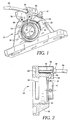
- FIGS. to 3 respectively illustrate levels 10 and 12 self-aligning recessed mount type and flanged, similar to the current flush mount but comprising an integrated sensor and components associates.
- a sensor target 14 is located at inside the landing (that is, between sealing devices) and is attached to and rotates with a rotating inner ring 16.
- a sensor 18 is also located inside the landing but is fixed on an inner surface of the sealing device 20 (or inside the sealing device 20) of so that the sensor 18 is in the immediate vicinity of the sensor target 14.
- the sealing device 20 is fixed on an outer ring 22 having a convex outer surface spherically mounted pivoting within a bore 24 of the housing 26 or 28.
- the sensor target 14 passes in front of the sensor 18 and an electrical signal is produced by the sensor 18 corresponding to the position of the sensor target 14.
- the signal produced by the sensor 18 is emitted outside the bearing at means of one or more electrical conductors comprising a flexible cable 30.
- the flexible cable 30 is separated from the median line of the landing to be conveyed radially towards a protective housing 32.
- the protective housing 32 is small, so that it does not interfere with access to bolts that can be used to fix bearings 10 or 12 recessed to automatic alignment of type to support or flange on a device.
- the protective housing 32 includes a portion forming "muzzle" 34 which protrudes radially towards the interior towards the center line of the bore 24 of the housing so that the part of snout 34 covers the electrical conductors of the flexible cable 30. In this way, the drivers electrical devices are protected from physical impacts. If the protective housing is made of a material electrically conductive, we also take certain interference protection measures electromagnetic.
- the snout portion 34 is formed so that the protective housing 32 can be made by molding or casting in the form of a single piece or multiple pieces and so that the muzzle portion 34 does not interfere with the oscillation inner and outer rings 16 and 22 by compared to housing 26 or 28.
- the protective housing 32 is formed so that it does not leave the area of the flange-type housing impression 28.
- the flush-mounted automatic flange type can be installed anywhere where is fixed the classical flush-type landing flange.
- the small size of the protection housing 32 reduces encroachment on the surrounding equipment.
- the length of the flexible cable 30 is sufficient for the protective housing 32 can be fixed on housing 26 or 28 once the inner and outer rings 16 and 22 installed in the housing and for the flexible cable 30 may be equipped with a system for limiting constraints.
- the protective housing 32 can be mounted in different positions. However, with the dwelling 26 of support type, it is preferred that the housing of protection 32 be located at about 90 degrees by ratio to the center line of the loading slots 36 and 38 that are used to install the ring 22. This location is preferred in order to reduce the risk of pinching or damaging the flexible cable 30 during installation when the inner and outer rings 16 and 22 (the sealing device 20 and flexible cable 30 being fixed) are introduced into the cavity of the slots loading 36 and 38 with an orientation perpendicular to the plane of housing 26 and turn then in the direction parallel to the housing plan 26. Thus, after the rotation in their final position inner and outer rings 16 and 22, the cable flexible 30 is in the twelve or six position hours, loading slots 36 and 38 being located in positions three and nine o'clock.
- the protective housing 32 can be designed to be fixed by small screws or fasteners 40 which are inserted from the back of housing 28. This construction may reduce access to sensor 18 and associated components.
- a lubricator 42 as a fastening element for securing or stowing in part the housing of protection 32 on the housing 26 or 28.
- the protective housing 32 can be attached from the rear, as illustrated with the flanged housing 28 or by small screws 44 threaded in the front part of the housing 26 as shown in Figure 1 or by a combination of these fasteners.
- the protective housing 32 can be filled with a protective material such as epoxy resin, silicone or a similar material.
- a protective material such as epoxy resin, silicone or a similar material.
- the protective housing 32 can be attached with an adhesive or with a material sealing to fill all spaces gaps between the protective housing 32 and the mating surfaces of the respective housing 26 or 28.
- the protective housing 32 can also be formed by molding or casting to be part integral of dwelling 26 or 28.
- Recessed Self-aligning Sensor Bearing integrated circuit of the present invention can be realized at using inner or outer rings that are not no larger than those of flush standard automatic alignment without sensors. The mounting of the sensor 18 on the inner surface or inside the sealing device 20, the cable flexible 30 coming out of the sealing device 20, allows to obtain a reduced volume set and a robust design with the sensor 18 located at inside the hermetic part of the bearing.
- Circuits for signal processing electrical signals emitted by the sensor 18 can be arranged on a circuit board 46, illustrated on the Figure 2, which can be a classic circuit board or can be a flexible printed circuit board some integrated length of circuit board flexible serves as a flexible cable 30.
- the circuit board flexible may have one or more layers of circuits and may consist of a polymer such as the Capton, with copper circuit ribbons.
- a Typical thickness for a flexible circuit board this type is between 0.005 and 0.011 inches.
- the sensor 18 may comprise components of soldered output sensor on a small PCB circuit fixed inside the sealing device bearing 20, the small circuit board being then connected to the cable 30 to carry the electrical signals from the components of sensor.
- the sensor 18 may comprise for example two Hall effect components 50 combined with circuits known electronic devices in order to produce speed, direction and / or position.
- the built-in construction described above can be used to get a thinner profile for the protection housing 32 and allow at least one part of the processing circuits to be placed at inside the sealing device 20, forming a alone holding with the sensor 18.
- the construction integrated removes the connections between different components, which offers an added benefit.
- the flexible circuit board can be maintained from rigid way inside the sealing device 20 bearing by connecting the flexible circuit board on a rigid surface 48 mounted on the inside of the bearing sealing device 20. Since the flexible circuit board comes out of the device 20, it serves as a flexible cable 30.
- This built-in construction facilitates installation, Alignment and adjustment of the bearing ring outside 22 inside dwelling 26 or 28 without damage the various components.
- the circuit board flexible can be placed in a sleeve or can be overmoulded with a protective rubber cover to provide additional protection.
- the sealing device 20 may comprise a metal frame 52 in the form of a ring with an overmolded elastomeric sealing lip 54 in engagement with the inner ring 16.
- the armature 52 presents a window cut, as shown in the figure 3, which allows the flexible cable 30 to move to through the sealing device 20 in the direction of the inner part of the landing, that is to say between the bearing sealing devices.
- the frame 52 can have a portion of outside diameter 70 wound, as shown in the figure, to be fixed at inside a groove 56 of the outer ring by snap engagement or engagement, as is often the case on devices bearing sealing or by other means of restraint known.
- a material cover Polymer 58 can be molded on the sealing window of the frame 52 to provide a system of limitation of stresses on the cable flexible 30 and direct the flexible cable 30 radially outward and then axially to outside. The cable 30 then curves radially towards the outside when it passes in the muzzle part 34, as shown in Figure 2, to the housing of protection 32.
- the cover in molded polymer material 58 also surrounds the sensor 18 and holds the sensor 18 to position it precisely with respect to the sensor target 14.
- the sensor target 14 can be a magnetic ring fixed on a steel frame 60 for example, which is mounted on the inner ring 16, as shown in the figure.
- the inner ring 16 and the ring outer 22 can be separated by balls 62 inside a retainer 64, such as the shows the figure, other types of bearings can be used with the present invention.
- the inner ring 16 and the outer ring 22 can be separated by pebbles or other rolling elements or by a sleeve or can have sliding surfaces in one piece forming a plain bearing for example.
- the protective housing 32 serves as a box of junction connecting the flexible cable 30 to a cable of robust transmission 66 and fixing for the cable of robust attachment 66, preferably provided with a system Restriction of constraints 68. It is necessary to understand that, if we use the built-in construction above, the circuit board 46 can be formed on a card flexible circuit and can be inserted inside of the sealing device, forming a single piece with the sensor 18. In this case, the size of the housing of protection could be reduced but would remain under the shape of a junction mounted in the housing connecting the flexible cable 30 and the transmission cable robust 66.
Landscapes
- Engineering & Computer Science (AREA)
- General Engineering & Computer Science (AREA)
- Mechanical Engineering (AREA)
- Physics & Mathematics (AREA)
- General Physics & Mathematics (AREA)
- Rolling Contact Bearings (AREA)
Claims (15)
- Selbsteinstellendes Einbaulager bestehend aus:Das besagte Lager besitzt weiterhin mindestens einen flexiblen elektrischen Leiter, der elektrisch mit dem Messfühler (18) angeschlossen ist, um die Ausgabe von Signalen durch den Messfühler (18) zu ermöglichen, ein Teil des flexiblen elektrischen Leiters ist dabei am Lagergehäuse (26 oder 28) befestigt.einem Lagergehäuse (26 oder 28) mit einer Bohrung (24) längs einer Achse,einem Innenring (16) und einem Außenring (22), der im vergleich zum Innenring (16) drehen kann; eine sphärisch-konvexe Außenfläche des Außenrings (22) ist derart im Innern der Bohrung (24) des Gehäuses (26) oder (28) befestigt, dass der Außenring (22) gegenüber der Achse der Bohrung (24) nicht eingestellt werden kann;einem am Innenring (16) befestigtes Messfühler-Target (14);einer am Außenring (22) befestigte Abdichtungsvorrichtung (20);einem auf der Abdichtungsvorrichtung (20) in Targetnähe montierten Messfühler (18).
- Selbsteinstellendes Einbaulager nach Patentanspruch 1, dahingehend gekennzeichnet, dass der flexible Leiter durch eine bestimmte integrierte Länge einer flexiblen Leiterkarte gebildet ist.
- Selbsteinstellendes Einbaulager nach Patentanspruch 2, dahingehend gekennzeichnet, dass die flexible Leiterkarte, die den Leiter bildet, zwei elektrische Stromkreise besitzt.
- Selbsteinstellendes Einbaulager nach Patentanspruch 1, dahingehend gekennzeichnet, dass ein auf dem Lagergehäuse (26 oder 28) montiertes Schutzgehäuse (32) vorhanden ist, das den flexiblen Leiter schützt und ermöglicht, diesen am Lagergehäuse (26 oder 28) zu befestigen.
- Selbsteinstellendes Einbaulager nach Patentanspruch 4, dahingehend gekennzeichnet, dass das Schutzgehäuse (32) mit dem flexiblen Leiter elektrisch verbundene Stromkreise besitzt.
- Selbsteinstellendes Einbaulager nach Patentanspruch 4, dahingehend gekennzeichnet, dass darüber hinaus ein Übertragungskabel (66) vorhanden ist, das elektrisch mit dem flexiblen Leiter verbunden ist.
- Selbsteinstellendes Einbaulager nach Patentanspruch 5, dahingehend gekennzeichnet, dass darüber hinaus ein Übertagungskabel (66) vorhanden ist, das elektrisch mit den Stromkreisen verbunden ist.
- Selbsteinstellendes Einbaulager nach Patentanspruch 4, dahingehend gekennzeichnet, dass das Schutzgehäuse (32) einen Nasenteil (34) besitzt, der radial über dem Außenring (22) verläuft, so dass der Nasenteil (34) dem flexiblen Leiter einen gewissen Schutz bietet.
- Selbsteinstellendes Einbaulager nach Patentanspruch 1, dahingehend gekennzeichnet, dass die Abdichtungsvorrichtung (20) eine metallische Fassung (52) besitzt, die auf dem Außenring (22) montiert ist; und diese Metallfassung (52) eine Öffnung bildet, durch die der flexible elektrische Leiter führt und dass die Abdichtungsvorrichtung (20) ebenfalls einen Teil aus Elastomer aufweist, der die Metallfassung abdeckt und eine Abdichtungslippe (54) bildet, die in den Innenring (16) eingreift.
- Selbsteinstellendes Einbaulager nach Patentanspruch 9, dahingehend gekennzeichnet, dass außerdem ein Käfig aus Polymermaterial (58) vorhanden ist, der auf der in der Metallfassung (52) praktizierten Öffnung und mindestens einem Teil des Messfühlers gegossen ist, so dass der Käfig aus Polymermaterial (58) den Messfühler stabilisiert.
- Selbsteinstellendes Einbaulager nach Patentanspruch 1, dahingehend gekennzeichnet, dass der Messfühler (18) mindestens ein Bauteil mit Halleffekt (50) besitzt.
- Selbsteinstellendes Einbaulager nach Patentanspruch 1, dahingehend gekennzeichnet, dass das Lagergehäuse (26 oder 28) ein Gehäuse vom Stehlagertyp (26) ist mit einem zentralen Bügel, der als Bohrung dient und zwei Befestigungsteile aufweist, die zur Befestigung des Lagers (26) ab dem zentralen Bügelteil nach Außen verlaufen, so dass die Bohrung (24) parallel zu einer Auflagefläche ausgerichtet ist.
- Selbsteinstellendes Einbaulager nach Patentanspruch 1, dahingehend gekennzeichnet, dass das Lagergehäuse (26 oder 28) ein Gehäuse vom Flanschlagertyp (28) ist mit einem zentralen Teil, der als Bohrung dienen kann und mindestens zwei Befestigungsteile aufweist, dies zur Befestigung des Lagers (28) ab dem zentralen Teil nach Außen verlaufen, so dass die Bohrung (24) transversal zu einer Auflagefläche ausgerichtet ist.
- Selbsteinstellendes Einbaulager nach Patentanspruch 1, dahingehend gekennzeichnet, dass das Messfühler-Target (14) einen magnetischen Ring besitzt, der auf einer auf dem Innenring (16) montierten Metallfassung (60) befestigt ist.
- Selbsteinstellendes Einbaulager nach Patentanspruch 1, dahingehend gekennzeichnet, dass darüber hinaus zwischen dem Innenring (16) und dem Außenring (22) positionierte Wälzelemente vorhanden sind.
Applications Claiming Priority (2)
| Application Number | Priority Date | Filing Date | Title |
|---|---|---|---|
| US6346697P | 1997-10-10 | 1997-10-10 | |
| US63466P | 1997-10-10 |
Publications (2)
| Publication Number | Publication Date |
|---|---|
| EP0908729A1 EP0908729A1 (de) | 1999-04-14 |
| EP0908729B1 true EP0908729B1 (de) | 2004-09-08 |
Family
ID=22049399
Family Applications (1)
| Application Number | Title | Priority Date | Filing Date |
|---|---|---|---|
| EP98402516A Expired - Lifetime EP0908729B1 (de) | 1997-10-10 | 1998-10-09 | Lager mit integriertem Sensor in Lagerbuchse |
Country Status (6)
| Country | Link |
|---|---|
| US (1) | US6007250A (de) |
| EP (1) | EP0908729B1 (de) |
| BR (1) | BR9804374A (de) |
| CA (1) | CA2249914A1 (de) |
| DE (1) | DE69826086T2 (de) |
| FR (1) | FR2769674B1 (de) |
Families Citing this family (18)
| Publication number | Priority date | Publication date | Assignee | Title |
|---|---|---|---|---|
| US6331823B1 (en) * | 1995-11-06 | 2001-12-18 | Reliance Electric Technologies, Llc | Monitoring system for bearings |
| DE19837640A1 (de) * | 1998-08-19 | 2000-04-06 | Siemens Ag | Elektronische Sensoranordnung |
| EP1203960B2 (de) * | 2000-11-06 | 2018-02-07 | Nsk Ltd | Wälzlagervorrichtung und Ring,der für die Wälzlagervorrichtung geeignet ist, mit integriertem Sensor |
| US20020141673A1 (en) * | 2001-03-28 | 2002-10-03 | Hiroyoshi Ito | Rolling bearing with rotation sensor |
| SE0101315L (sv) * | 2001-04-12 | 2002-09-10 | Skf Ab | Lagerhus med en mätanordning |
| US6564635B2 (en) | 2001-09-14 | 2003-05-20 | Pete D. Sherman | Bearing assembly with integral sensor for sensing rotation |
| FR2843430B1 (fr) * | 2002-08-07 | 2005-03-18 | Roulements Soc Nouvelle | Systeme integre de fixation et de connection d'un capteur |
| DE102004030439B4 (de) * | 2004-06-24 | 2008-06-19 | Ab Skf | Lager |
| US7250756B1 (en) * | 2006-02-09 | 2007-07-31 | Timken Us Corporation | Flexible sensor input assembly |
| FR2910129B1 (fr) * | 2006-12-15 | 2009-07-10 | Skf Ab | Dispositif de palier a roulement instrumente |
| US8497468B2 (en) * | 2007-12-20 | 2013-07-30 | Heidenhain Corporation | Encoder having an overmolded cover, encoder system with an encoder having an overmolded cover, and method for manufacturing an encoder having an overmolded cover |
| WO2010064088A1 (en) * | 2008-12-02 | 2010-06-10 | Aktiebolaget Skf | Rolling bearing with integrated sensor |
| FR3027977B1 (fr) * | 2014-10-30 | 2016-12-09 | Skf Ab | Palier a roulement avec bague exterieure en forme de troncon de sphere et avec un organe capteur |
| FR3035695B1 (fr) * | 2015-04-29 | 2017-11-24 | Skf Ab | Roulement instrumente auto-ajustable et systeme mecanique equipe d'un tel roulement |
| US20180106323A1 (en) * | 2015-05-04 | 2018-04-19 | Lord Corporation | Instrumented flexible load bearing connector |
| FR3080656B1 (fr) * | 2018-04-26 | 2020-05-22 | Ntn-Snr Roulements | Palier a roulement |
| JP7680664B2 (ja) * | 2020-12-07 | 2025-05-21 | 株式会社不二越 | 回転センサ付き軸受装置 |
| US11566670B1 (en) | 2021-12-16 | 2023-01-31 | Regal Beloit America, Inc. | Sensor bearing housing |
Citations (2)
| Publication number | Priority date | Publication date | Assignee | Title |
|---|---|---|---|---|
| EP0137270A2 (de) * | 1983-09-28 | 1985-04-17 | Werkzeugmaschinenfabrik Oerlikon-Bührle AG | Messgeber für Gleit- und Schleuderschutzanlagen zum Messen von Fahrzeugachsdrehzahlen |
| FR2668561A1 (fr) * | 1990-10-30 | 1992-04-30 | Roulements Soc Nouvelle | Roulement a capteur d'informations. |
Family Cites Families (14)
| Publication number | Priority date | Publication date | Assignee | Title |
|---|---|---|---|---|
| CA1333964C (en) * | 1988-08-24 | 1995-01-17 | David E. Peck | Unitary rotational speed sensor |
| FR2671633B1 (fr) * | 1991-01-10 | 1993-04-16 | Skf France | Dispositif de capteur de vitesse de rotation integre dans un moyeu a roulement. |
| IT222913Z2 (it) * | 1991-02-08 | 1995-05-09 | Skf Ind Spa | Guscio protettivo con appendice di rinvio e connettore dei cavi |
| FR2698421B1 (fr) * | 1992-11-24 | 1995-06-02 | Skf France | Logement pour fixation radiale d'un roulement. |
| FR2701298B1 (fr) * | 1993-02-05 | 1995-03-10 | Roulements Soc Nouvelle | Roulement à capteur d'informations perfectionné. |
| US5439296A (en) * | 1993-06-04 | 1995-08-08 | Reliance Electric Industrial Company | Bearing housing with temperature switch |
| FR2706956B1 (de) * | 1993-06-25 | 1995-08-18 | Roulements Soc Nouvelle | |
| DE4326391C2 (de) * | 1993-08-06 | 1997-04-30 | Licentia Gmbh | Dreherkennungsvorrichtung für einen Kommutatormotor |
| US5433525A (en) * | 1993-08-13 | 1995-07-18 | Reliance Electric Industrial Company | Bearing housing with embedded temperature measurement device |
| FR2712048B1 (fr) * | 1993-11-04 | 1995-12-15 | Roulements Soc Nouvelle | Joint d'étanchéité pour roulements à capteur d'informations et roulement ainsi équipé. |
| JPH08122351A (ja) * | 1994-10-27 | 1996-05-17 | Ntn Corp | 回転センサを備える車輪支持軸受 |
| JP3309594B2 (ja) * | 1994-11-04 | 2002-07-29 | 日本精工株式会社 | 回転速度検出装置付転がり軸受ユニット |
| JPH08178938A (ja) * | 1994-12-27 | 1996-07-12 | Nippon Seiko Kk | 回転速度検出装置付転がり軸受ユニット |
| JP3635707B2 (ja) * | 1995-03-03 | 2005-04-06 | 日本精工株式会社 | 回転速度検出装置付転がり軸受ユニット |
-
1998
- 1998-09-22 US US09/158,957 patent/US6007250A/en not_active Expired - Lifetime
- 1998-10-09 DE DE69826086T patent/DE69826086T2/de not_active Expired - Lifetime
- 1998-10-09 BR BR9804374-9A patent/BR9804374A/pt not_active IP Right Cessation
- 1998-10-09 FR FR9812690A patent/FR2769674B1/fr not_active Expired - Fee Related
- 1998-10-09 EP EP98402516A patent/EP0908729B1/de not_active Expired - Lifetime
- 1998-10-09 CA CA002249914A patent/CA2249914A1/en not_active Abandoned
Patent Citations (2)
| Publication number | Priority date | Publication date | Assignee | Title |
|---|---|---|---|---|
| EP0137270A2 (de) * | 1983-09-28 | 1985-04-17 | Werkzeugmaschinenfabrik Oerlikon-Bührle AG | Messgeber für Gleit- und Schleuderschutzanlagen zum Messen von Fahrzeugachsdrehzahlen |
| FR2668561A1 (fr) * | 1990-10-30 | 1992-04-30 | Roulements Soc Nouvelle | Roulement a capteur d'informations. |
Also Published As
| Publication number | Publication date |
|---|---|
| US6007250A (en) | 1999-12-28 |
| EP0908729A1 (de) | 1999-04-14 |
| FR2769674A1 (fr) | 1999-04-16 |
| BR9804374A (pt) | 2000-02-15 |
| DE69826086T2 (de) | 2005-09-22 |
| DE69826086D1 (de) | 2004-10-14 |
| FR2769674B1 (fr) | 2000-03-31 |
| CA2249914A1 (en) | 1999-04-10 |
Similar Documents
| Publication | Publication Date | Title |
|---|---|---|
| EP0908729A1 (de) | Lager mit integriertem Sensor in Lagerbuchse | |
| EP0652438B1 (de) | Wasserdichte Abdichtung für Wälzlager mit Messaufnehmer und damit ausgerüstetes Wälzlager | |
| EP0726468B1 (de) | Kodiervorrichtung für Geschwindigkeitsmessaufnehmer sowie ein mit einer solchen Vorrichtung versehenes Wälzlager | |
| EP0454547B1 (de) | Rollennabe mit Sensoreinrichtung zur Erfassung der Drehzahl | |
| EP0631140B1 (de) | Lager mit integriertem Messwertaufnehmer | |
| EP0872652B1 (de) | Wälzlager mit Messwertenaufnehmer | |
| EP0387459A2 (de) | Gleitlageranordnung mit auswechselbarem Messaufnehmer | |
| EP0453331A1 (de) | Wälzlager, das mit einem verstellbaren Informationssensor ausgerüstet ist | |
| FR2900281A1 (fr) | Connecteur pour liaison a haut debit et carte electronique munie d'un tel connecteur | |
| FR2874433A1 (fr) | Dispositif a capteur magnetique ayant des composants montes sur un aimant | |
| EP0919813B1 (de) | Schutzvorrichtung für eine magnetische Kodiereinrichtung | |
| EP0875683A1 (de) | Wälzlager mit Messwertgeber | |
| FR2843430A1 (fr) | Systeme integre de fixation et de connection d'un capteur | |
| EP0861019B1 (de) | Schutzgehäuse für eine Leiterplatte | |
| FR2854985A3 (fr) | Ensemble de reception satellite pliable. | |
| CA2806972A1 (fr) | Systeme de fixation d'elements magnetiques dans une machine electrique a aimants permanents | |
| EP1251354A1 (de) | Dichtungsanordnung für ein mit Drehgeschwindigkeitsmessaufnehmern ausgestattetes Wälzlager | |
| EP1544696A2 (de) | Tragbares elektronisches Gerät, das mit einem Drucksensor ausgerüstet ist | |
| WO2005087544A1 (fr) | Dispositif avertisseur par vibrations et siege comportant un tel dispositif | |
| FR2533084A1 (fr) | Dispositif de maintien pour moteur electrique de petit modele | |
| FR2759777A1 (fr) | Dispositif pour mesurer la rotation d'un element rotatif | |
| FR2468783A1 (fr) | Bague elastique et montage en comportant application | |
| FR3027387A1 (fr) | Dispositif detecteur a constitution modulaire et equipement industriel le comportant | |
| FR2858746A1 (fr) | Appareil electronique | |
| EP0694765A1 (de) | Herstellung von Sensoren, die physische oder elektrische Werte messen |
Legal Events
| Date | Code | Title | Description |
|---|---|---|---|
| PUAI | Public reference made under article 153(3) epc to a published international application that has entered the european phase |
Free format text: ORIGINAL CODE: 0009012 |
|
| AK | Designated contracting states |
Kind code of ref document: A1 Designated state(s): DE ES FR GB IT SE |
|
| AX | Request for extension of the european patent |
Free format text: AL;LT;LV;MK;RO;SI |
|
| RTI1 | Title (correction) | ||
| AKX | Designation fees paid |
Free format text: DE ES FR GB IT SE |
|
| 17P | Request for examination filed |
Effective date: 19991220 |
|
| R17P | Request for examination filed (corrected) |
Effective date: 19990910 |
|
| 17Q | First examination report despatched |
Effective date: 20011008 |
|
| GRAP | Despatch of communication of intention to grant a patent |
Free format text: ORIGINAL CODE: EPIDOSNIGR1 |
|
| GRAS | Grant fee paid |
Free format text: ORIGINAL CODE: EPIDOSNIGR3 |
|
| GRAA | (expected) grant |
Free format text: ORIGINAL CODE: 0009210 |
|
| AK | Designated contracting states |
Kind code of ref document: B1 Designated state(s): DE ES FR GB IT SE |
|
| PG25 | Lapsed in a contracting state [announced via postgrant information from national office to epo] |
Ref country code: IT Free format text: LAPSE BECAUSE OF FAILURE TO SUBMIT A TRANSLATION OF THE DESCRIPTION OR TO PAY THE FEE WITHIN THE PRE;WARNING: LAPSES OF ITALIAN PATENTS WITH EFFECTIVE DATE BEFORE 2007 MAY HAVE OCCURRED AT ANY TIME BEFORE 2007. THE CORRECT EFFECTIVE DATE MAY BE DIFFERENT FROM THE ONE RECORDED.SCRIBED TIME-LIMIT Effective date: 20040908 Ref country code: GB Free format text: LAPSE BECAUSE OF FAILURE TO SUBMIT A TRANSLATION OF THE DESCRIPTION OR TO PAY THE FEE WITHIN THE PRESCRIBED TIME-LIMIT Effective date: 20040908 |
|
| REG | Reference to a national code |
Ref country code: GB Ref legal event code: FG4D Free format text: NOT ENGLISH |
|
| PGFP | Annual fee paid to national office [announced via postgrant information from national office to epo] |
Ref country code: GB Payment date: 20040927 Year of fee payment: 7 |
|
| PGFP | Annual fee paid to national office [announced via postgrant information from national office to epo] |
Ref country code: SE Payment date: 20041012 Year of fee payment: 7 |
|
| REF | Corresponds to: |
Ref document number: 69826086 Country of ref document: DE Date of ref document: 20041014 Kind code of ref document: P |
|
| PGFP | Annual fee paid to national office [announced via postgrant information from national office to epo] |
Ref country code: ES Payment date: 20041020 Year of fee payment: 7 |
|
| PG25 | Lapsed in a contracting state [announced via postgrant information from national office to epo] |
Ref country code: SE Free format text: LAPSE BECAUSE OF FAILURE TO SUBMIT A TRANSLATION OF THE DESCRIPTION OR TO PAY THE FEE WITHIN THE PRESCRIBED TIME-LIMIT Effective date: 20041208 |
|
| PG25 | Lapsed in a contracting state [announced via postgrant information from national office to epo] |
Ref country code: ES Free format text: LAPSE BECAUSE OF FAILURE TO SUBMIT A TRANSLATION OF THE DESCRIPTION OR TO PAY THE FEE WITHIN THE PRESCRIBED TIME-LIMIT Effective date: 20041219 |
|
| GBV | Gb: ep patent (uk) treated as always having been void in accordance with gb section 77(7)/1977 [no translation filed] |
Effective date: 20040908 |
|
| PLBE | No opposition filed within time limit |
Free format text: ORIGINAL CODE: 0009261 |
|
| STAA | Information on the status of an ep patent application or granted ep patent |
Free format text: STATUS: NO OPPOSITION FILED WITHIN TIME LIMIT |
|
| 26N | No opposition filed |
Effective date: 20050609 |
|
| REG | Reference to a national code |
Ref country code: FR Ref legal event code: PLFP Year of fee payment: 18 |
|
| REG | Reference to a national code |
Ref country code: FR Ref legal event code: PLFP Year of fee payment: 19 |
|
| REG | Reference to a national code |
Ref country code: FR Ref legal event code: PLFP Year of fee payment: 20 |
|
| PGFP | Annual fee paid to national office [announced via postgrant information from national office to epo] |
Ref country code: FR Payment date: 20171024 Year of fee payment: 20 Ref country code: DE Payment date: 20171019 Year of fee payment: 20 |
|
| REG | Reference to a national code |
Ref country code: DE Ref legal event code: R071 Ref document number: 69826086 Country of ref document: DE |