EP0908846A2 - Méthode et appareil de détection d'un objet en mouvement - Google Patents
Méthode et appareil de détection d'un objet en mouvement Download PDFInfo
- Publication number
- EP0908846A2 EP0908846A2 EP98307946A EP98307946A EP0908846A2 EP 0908846 A2 EP0908846 A2 EP 0908846A2 EP 98307946 A EP98307946 A EP 98307946A EP 98307946 A EP98307946 A EP 98307946A EP 0908846 A2 EP0908846 A2 EP 0908846A2
- Authority
- EP
- European Patent Office
- Prior art keywords
- predetermined
- detecting
- image
- size
- moving object
- Prior art date
- Legal status (The legal status is an assumption and is not a legal conclusion. Google has not performed a legal analysis and makes no representation as to the accuracy of the status listed.)
- Ceased
Links
Images








Classifications
-
- G—PHYSICS
- G06—COMPUTING OR CALCULATING; COUNTING
- G06T—IMAGE DATA PROCESSING OR GENERATION, IN GENERAL
- G06T7/00—Image analysis
- G06T7/60—Analysis of geometric attributes
-
- G—PHYSICS
- G06—COMPUTING OR CALCULATING; COUNTING
- G06T—IMAGE DATA PROCESSING OR GENERATION, IN GENERAL
- G06T2207/00—Indexing scheme for image analysis or image enhancement
- G06T2207/10—Image acquisition modality
- G06T2207/10016—Video; Image sequence
-
- G—PHYSICS
- G06—COMPUTING OR CALCULATING; COUNTING
- G06T—IMAGE DATA PROCESSING OR GENERATION, IN GENERAL
- G06T2207/00—Indexing scheme for image analysis or image enhancement
- G06T2207/30—Subject of image; Context of image processing
- G06T2207/30196—Human being; Person
-
- G—PHYSICS
- G06—COMPUTING OR CALCULATING; COUNTING
- G06T—IMAGE DATA PROCESSING OR GENERATION, IN GENERAL
- G06T2207/00—Indexing scheme for image analysis or image enhancement
- G06T2207/30—Subject of image; Context of image processing
- G06T2207/30232—Surveillance
Definitions
- the present invention relates to an image processing apparatus and an image processing method of detecting a desired object from input image data.
- One conventional moving object detection apparatus detects an intruder or abnormality by detecting a moving object in an image being taken by a video camera for a monitoring purpose or the like.
- the size of a moving object to be detected by such an apparatus is previously known. Therefore, it is desirable to so design an apparatus that the apparatus detects only a moving object of a specific size.
- an image pickup device such as a video camera
- the size of an object changes in accordance with the distance to the object or the magnification.
- an image pickup system has an image pickup center 120 and an optical axis 127.
- Planes 121, 122, and 123 are perpendicular to the optical axis 127 and at distances of 1, 2, and 3 m, respectively, from the image pickup center 120.
- Spheres 124, 125, and 126 have a radius of 1/3 m, and their centers are in the planes 121, 122, and 123, respectively.
- the horizontal and vertical field angles of this image pickup system are 36.0° and 27.0°, respectively.
- Fig. 1 shows the horizontal field angle viewed from immediately above. Lines 129 and 130 indicate the field angle range viewed from the image pickup center 120.
- the angle formed by 130 - 120 - 129 is 36.0°. Both of 127 - 120 - 129 and 127 - 120 - 130 form an angle of 18°.
- An image picked up by this image pickup system is formed by 640 pixels (horizontal direction) x 480 lines (vertical direction).
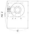
- Fig. 2 shows the sizes of the spheres 124, 125, and 126 in an image frame captured by 640 x 480 pixels described above.
- images of objects having exactly the same size have different sizes in the frame in accordance with their distances from the image pickup center.
- the sphere 124 shown in Fig. 1 occupies a horizontal field angle of about 19° (the angle formed by A - 120 - A') across its diameter and has an image size of about 327 pixels in the frame.
- the sphere 125 occupies about 9.5° (the angle formed by B - 120 - B') and has an image size of about 163 pixels.
- the sphere 126 occupies about 6.4° and has an image size of 109 pixels.
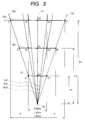
- Fig. 3 shows results when the image pickup system optically changes its magnification.
- D 1 - 120 - D 1 ' indicates a field angle of about 36.0° obtained at a reference magnification of 1 ⁇ .
- D 2 - 120 - D 2 ' indicates a field angle of about 18.5° obtained when the magnification is 2 ⁇ .
- D 3 - 120 - D 3 ' indicates a field angle of about 12.4° obtained when the magnification is 3 ⁇ .
- a field angle corresponding to 640 pixels of the frame size of an image changes.
- the magnification is increased, the image size of an object increases in proportion to the magnification. That is, the object size relative to the image frame size increases.
- a monitoring area for a moving object to be detected by a moving object detection apparatus is often limited. So, it is desirable to allow the apparatus to detect a moving object only in a part of an image area being picked up.
- Fig. 4 shows an image taken at a certain fixed field angle by a video camera.
- Fig. 5 shows a detection area 101 set in the image shown in Fig. 4.
- This detection area 101 is composed of a plurality of rectangular areas 100 as a minimum unit including n x m pixels (e.g., 16 x 12 pixels or 24 x 24 pixels).
- This detection area 101 is used to, e.g., detect an object which is intruding into an area surrounded by a fence 102 in the image shown in Fig. 4.
- the specific detection area 101 is set in an image picked up at a certain fixed angle, and image changes in this specific area are detected. Therefore, not only changes in a monitoring area to be detected but also changes which need not be detected or should not be detected are detected.
- the setting of the field angle e.g., install a video camera above the monitoring area.
- the setting of the field angle is not always selectable. Also, accidental detection of an object flying over the monitoring area is unavoidable.
- the present invention has been made in consideration of the above situation and has as a concern to provide an image processing apparatus/method capable of detecting an object (e.g., an object of a predetermined size or an object within a predetermined distance range from a predetermined object) desired by a user from input image data.
- an object e.g., an object of a predetermined size or an object within a predetermined distance range from a predetermined object
- an image processing apparatus/method is characterized by inputting image data, detecting an object in the input image data, measuring the distance from the detected object to a predetermined position, and detecting a predetermined object on the basis of the measurement result.
- an image processing apparatus/method characterized by inputting image data by image pickup means having an optical system, detecting an object in the input image data, controlling the optical system of the image pickup means, and detecting a predetermined object on the basis of the object detection result and the optical system control result.
- Fig. 8 is a block diagram showing the arrangement of a moving object detection apparatus according to the first embodiment of the present invention.
- a phototaking lens 12 with a zooming function includes a zooming lens 1 for changing the magnification and a focusing lens 2 for focusing.
- This phototaking lens 12 forms an optical image of an object on the imaging surface of an image pickup element 3 such as a CCD.
- the image pickup element 3 outputs an electrical signal indicating the optical image to a camera processing unit 4.
- the camera processing unit 4 performs well-known processes (e.g., gain correction, ⁇ correction, and color balance adjustment) for the output from the image pickup element 3 and outputs a video signal of a predetermined format.
- a focus detection area setting unit 7 designates an image area to be automatically focused by a focusing control unit 8.
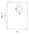
- Fig. 9 is a view showing an example of the focus detection area in an image.
- an image area 31 is a digital image composed of 640 x 480 pixels.
- a rectangular area composed of 140 x 140 pixels in this image area 31 is indicated as a focus detection area 32.
- a circular object 33 is shown as a principal object present in the focus detection area 32.
- the focus detection area 32 is relative positional information on the imaging surface, which indicates an area in the imaging surface having an object image to be focused.
- This focus detection area 32 is set in the focusing control unit 8 via the focus detection area setting unit 7 under the control of a system control unit 20.
- the focusing control unit 8 moves and adjusts the position of the focusing lens 2 along its optical axis by controlling a focusing lens motor (stepping motor) (not shown) so as to maximize a high-frequency component contained in a portion of the output image signal from the camera processing unit 4, which corresponds to the area set by the focus detection area setting unit 7, thereby automatically focusing the focusing lens 2 on the object.
- a focusing lens motor stepping motor
- the position of the focusing lens 2 (the lens position at any arbitrary timing within a position range over which the focusing motor can drive the focusing lens) is externally output from the focusing control unit in the form of, e.g., a pulse number indicating the number of pulses by which the focusing lens motor is driven from its reference position.
- a magnification setting unit 9 sets a target magnification when a zoom control unit 10 moves and adjusts the position of the zooming lens 1 along its optical axis by driving a zooming lens motor (stepping motor) (not shown), thereby controlling zooming.
- This magnification setting unit 9 receives a set magnification from the system control unit 20 and sets the set magnification in the zoom control unit 10 as a zooming motor driving pulse value corresponding the magnification as a zooming lens motor control set value.
- the zoom control unit 10 controls the zooming lens motor to move and adjust the position of the zooming lens 1 along its optical axis and thereby enables image formation zoomed to a desired magnification.
- the position of the zooming lens 1 is externally output from the zoom control unit 10 in the form of, e.g., a pulse number indicating the number of pulses by which the zooming lens motor is driven from the reference position.
- a pulse number indicating the number of pulses by which the zooming lens motor is driven from the reference position.
- a moving object detection unit 5 detects a moving object in an image from the output video signal from the camera processing unit 4.
- a moving object detection method of this sort a method using background difference is known. That is, as shown in Fig. 10, an image 41 containing no moving object in an observation area is previously picked up and stored. Next, a monitor image 42 (an image currently being picked up) obtained during observation is compared with the image 41 to produce a difference image 43 by calculating the difference between the pixel values of each pair of corresponding pixels.
- This difference image 43 has signification pixel values only in a portion different from the image 41 previously stored and containing no moving object.
- An area 44 contained in the difference image 43 and composed of pixels having significant pixel values (values much larger than zero) is detected as a moving object.
- Whether the size (e.g., the number of pixels contained in the area 44) of the detected moving object corresponds to a previously assumed size is checked, thereby checking whether the moving object is a desired object having a size to be detected.
- a moving object size correction unit 21 corrects the size of the detected moving object to a size obtained when the object is detected at a reference distance and a reference magnification, in accordance with the distance from the camera to the moving object. This allows detection of a moving object of a specific size within a broader range than in conventional methods.
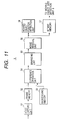
- a video capture unit 51 receives the output video signal from the camera processing unit 4 shown in Fig. 8 and writes a digital image in units of frames in a frame memory 52.
- a background memory 53 stores an image, such as the background image 41 taken with no moving object present, which is previously picked up by an initializing circuit (not shown) before monitoring is started.
- a difference operation unit 54 receives pixel values obtained by simultaneously reading out corresponding pixels of the two images held in the frame memory 52 and the background memory 53 in the scanning order and outputs values (absolute values) obtained by subtracting the output pixel values from the background memory 53 from the output pixel values from the frame memory 52.
- the differences (absolute values) in one frame output from the difference operation unit 54 are arranged in the scanning order, the difference image 43 shown in Fig. 10 is obtained.
- a binarizing unit 55 binarizes the output from the difference operation unit 54 by using a predetermined threshold value regarded as a significant value and sequentially outputs pixel values, 1 (ON: black) for pixels in an area in which the two images have a significant difference and 0 (OFF: white) for other pixels, in the scanning order.
- a noise removal unit 56 removes, e.g., isolated pixels, fine black pixel areas, and fine holes (fine white pixel areas in continuous black pixel areas) produced by noise mixed for various causes during the processes described so far.
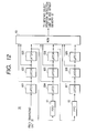
- Fig. 12 shows the arrangement of the noise removal unit 56.
- Each of FIFO memories 61 and 62 holds data corresponding to the number of pixels on one scanning line. That is, the FIFO 61 holds input data one line before the current scanning line. The FIFO 62 holds input data two lines before the current scanning line.
- the latches 601 to 603 hold bit data corresponding to three pixels on the current scanning line.
- the latches 604 to 606 hold bit data corresponding to three pixels on a scanning line adjacent (in the subscanning direction) to the current scanning line.
- a ROM 63 receives the nine output bits from the latches 601 to 609 as address input and outputs 1-bit data in accordance with the states of the nine output bits from the latches 601 to 609.
- the ROM 63 previously holds data by which the ROM 63 outputs 1 when five bits or more of the nine input address bits are 1 and outputs 0 when five bits or more of the nine input address bits are 0. That is, the ROM 63 is so set as to output black pixels when five pixels or more in the 3 x 3-pixel area are black pixels and output white pixels when four pixels or less in the area are black pixels. Isolated pixels can be removed by using the ROM 63 as a lookup table as described above.
- This noise removal unit 56 is a pipeline processing circuit, so an output is delayed by one scanning line and by one pixel from the input. However, binary pixels from which noise is already removed are sequentially output in the raster scan order.
- a bit map memory 57 stores the binary pixel data of one frame output from the noise removal unit 56.
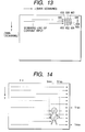
- a moving object position detection unit 58 sequentially receives the noise-removed binary image data in the raster scan order as shown in Fig. 14 and detects coordinate values (X min ,Y min ) and (X max ,Y max ) indicating a rectangular area 81 surrounding a black pixel area as shown in Figs. 15A and 15B. These coordinate values can be easily detected by a known circuit basically including counters and comparators.
- a counter for detecting X min counts pixels in the main scanning direction until a black pixel appears for the first time in data on each scanning line (i.e., counts synchronizing pulses (not shown) in the main scanning direction).
- a comparator compares this count with a value counted on previous scanning lines and held in a buffer for holding X min . If the counter value is smaller than the buffer value, the value held in the X min buffer is replaced with the current count; if not, the value held in the X min buffer is not changed.
- the value of the X min buffer is initialized to a value larger than the number of pixels contained in one main scanning line every time a line is scanned.
- X max it is only necessary to detect pixel position on a main scanning line when a white pixel is detected after a black pixel is detected on the scanning line (i.e., to count main scanning synchronizing pulses until a change from a black pixel to a white pixel is detected). If this X max value is larger than a previous X max value, the X max value is updated; if not, the X max value is not updated.
- Y min it is only necessary to count scanning lines (subscanning synchronizing pulses) scanned before a scanning line containing a black pixel is first detected. To obtain Y max , it is only necessary to count scanning lines before a scanning line containing no black pixel is again detected after a scanning line containing a black pixel is detected.
- a moving object size detection unit 6 shown in Fig. 8 detects the size of the moving object on the basis of the output values (X min ,Y min ) and (X max ,Y max ) from the moving object detection unit 5 and the noise-removed binary image data held in the bit map memory 57 shown in Fig. 11.
- Fig. 16 shows the arrangement of the moving object size detection unit 6.
- a scanning clock generation unit 91 receives the coordinates (X min ,Y min ) and (X max ,Y max ) of the diagonal points of the rectangular area surrounding the moving object from the moving object detection unit 5 and sequentially generates (in a raster scan form) addresses for accessing only the rectangular area in a bit map memory 92.
- the scanning clock generation unit 91 generates scanning clocks for (X max - X min + 1) pixels from X min to X max in the main scanning direction and scanning clocks for (Y max - Y min + 1) scanning lines from Y min to Y max in the subscanning direction, thereby converting the area 81 shown in Fig. 15A into a binary image 82, shown in Fig. 15B, composed of (X max - X min + 1) x (Y max - Y min + 1) pixels.
- a counter 94 counts only black pixels (i.e., when black pixels are output as pixel value 1 and a white pixels are output as pixel value 0, counts only pixel values 1 output in this raster scan form) in the binary image having (X max - X min + 1) x (Y max - Y min + 1) pixels output from the bit map memory 92. In this manner the counter 94 counts the number of black pixels as the area of the extracted moving object. This number (area) of black pixels is the moving object size.
- An initialization/read-out unit 93 initializes the scanning clock generation unit 91 and the counter 94 under the control of the system control unit 20 shown in Fig. 8. Also, the initialization/read-out unit 93 reads out the count from the counter 94 and outputs the readout count to the system control unit 20.
- a distance measurement unit 11 shown in Fig. 8 will be described below.
- This distance measurement unit 11 receives a focusing lens motor driving pulse number (a pulse number indicating the number of pulses by which the focusing lens motor is driven from the reference position to the current position). This pulse number is output from the focusing control unit 8 and indicates the position of the focusing lens 2.
- the distance measurement unit 11 also receives a zooming lens motor driving pulse number (a pulse number indicating the number of pulses by which the zooming lens motor is driven from the reference position to the current position). This pulse number is output from the zoom control unit 10 and indicates the position of the zooming lens 1.
- the distance measurement unit 11 outputs the distance from the camera to an object on which the camera is focusing.
- a rear focus lens For this rear focus lens, the focal point moves when the position of the zooming lens 1 is changed. Accordingly, an in-focus image can be obtained only when the focusing lens 2 is also moved.
- the position (i.e., the focusing lens motor pulse number) of the focusing lens 2 is changed to various values, and the distance from the camera to an object to be focused is previously actually measured for each of these positions.
- a lookup table is formed which receives the position (the zooming motor driving pulse number required to move from the reference position) of the zooming lens 1 and the position (the focusing lens motor driving pulse number required to move from the reference position) of the focusing lens 2 as addresses and outputs the corresponding distance from the camera to an object to be focused as data.
- This lookup table is implemented by a ROM.
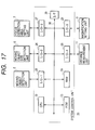
- Fig. 17 shows the arrangement of the system control unit 20.
- the system control unit 20 includes a CPU 22, a ROM 23 storing programs as a storage medium according to the present invention, a RAM 24, I/O ports 25 to 29, a communication interface 39, and a bus 30.
- the CPU 22 reads out the programs stored in the ROM 23 and operates in accordance with the program procedures. In the course of the operation, the CPU 22 holds information required to be temporarily held and information changing in accordance with the situation in the RAM 24.
- the storage medium it is also possible to use a semiconductor memory, an optical disk, a magnetooptical disk, or a magnetic medium.
- the I/O ports 25, 26, 27, 28, and 29 interface the CPU 22 with the moving object detection unit 5, the moving object size detection unit 6, the focus detection area setting unit 7, the distance measurement unit 11, and the magnification setting unit 9, respectively.
- the communication interface 39 communicates with external apparatuses. For example, the communication interface 39 receives the size of a moving object to be detected from an external apparatus or, when a moving object with a desired size is detected, informs an external apparatus of the detection.
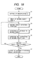
- step S1 the CPU 22 receives a desired magnification D from an external host computer via the communication interface 39.
- the CPU 22 sets the input magnification D in the magnification setting unit 9 via the I/O-5 (29) shown in Fig. 17.
- the magnification setting unit 9 causes the zoom control unit 10 to control the zooming lens motor in accordance with the magnification D and sets the desired magnification D in the apparatus.
- step S1 the flow advances to step S2, and the CPU 22 receives a size S of a moving object to be detected from the external host computer via the communication interface 39.
- the CPU 22 holds the input size information S in a predetermined area of the RAM 24.
- this moving object size S the number of pixels (in the case of the sphere 124 shown in Fig. 1, approximately 84,000 pixels contained in the sphere 124 shown in Fig. 2) at a field angle when the camera used in this system are set at a reference distance (in this embodiment, 1 m) and a reference magnification (in this embodiment, a magnification when the horizontal field angle is 36° and the vertical field angle is 27° is a reference magnification of 1x) is input.
- step S3 the CPU 22 starts a loop (steps S3 to S6) of detecting a moving object with a desired size.
- Fig. 19 shows details of step S3. Referring to Fig. 19, in step S30 the CPU 22 accesses the moving object detection unit 5 via the I/O-1 (25) and reads out the diagonal point coordinates (X min ,Y min ) and (X max ,Y max ) of the rectangular area 81 surrounding a moving object from the moving object position detection unit 58.
- step S32 the CPU 22 sets the coordinates (Xc,Yc) of the central point of the rectangular area surrounding the moving object, which are calculated in step S31, in the focusing control unit 8 via the I/P-3 (27) and the focus detection area setting unit 7. In this manner the CPU 22 sets the moving object as a focused object of distance measurement by the distance measurement unit 11.
- step S3 the CPU 22 returns to the routine shown in Fig. 18, and the flow advances to step S4.
- step S4 the CPU 22 detects the distance to the moving object.
- Fig. 20 shows details of step S4.
- the CPU 22 receives a signal indicating whether the focusing control unit 8 determines that the moving object is in-focus via the focus detection area setting unit 7, thereby checking whether the moving object is in-focus. If the moving object is not in-focus, the CPU 22 repeats the process in step S40. If the moving object is in-focus, the flow advances to step S41.
- the CPU 22 reads out information Lo about the distance to the focused object from the distance measurement unit 11 via the I/O-4 (28) shown in Fig. 17. The flow then advances to step S42.
- Lo expresses distance from 0 mm to ⁇ as an 8- or 16-bit code.
- the CPU 22 decodes the distance Lo to a distance L (m) from the camera to the focused object on the basis of a correspondence table (not shown) previously registered in the program.
- step S4 After completing the series of processes in step S4, the CPU 22 returns to the routine shown in Fig. 18, and the flow advances to step S5.
- Fig. 21 shows details of step S5.
- step S50 the CPU 22 accesses the moving object detection unit 6 via the I/O-2 (26) shown in Fig. 17 to receive a moving object size (pixel number) So.
- step S5 the CPU 22 returns to the routine shown in Fig. 18, and the flow advances to step S6.
- step S6 the CPU 22 checks whether the ratio of the size S' calculated in step S51 to the size S of the moving object to be detected, which is input in step S2 and held in the RAM 24, falls within a predetermined range. That is, the CPU 22 checks whether 0.8 ⁇ S'/S ⁇ 1.2 thereby checking whether the moving object has a desired size.
- step S3 If the moving object does not have a desired size, i.e., if 0.8 ⁇ S'/S or 1.2 ⁇ S'/S the flow returns to step S3, and the CPU 22 repeats the procedure from moving object detection.
- step S7 If the moving object has a desired size, i.e., if 0.8 ⁇ S'/S ⁇ 1.2 the flow advances to step S7.
- step S7 the CPU 22 informs the external apparatus of the detection of the moving object with a desired size via the communication interface 39.
- the CPU 22 completes the procedure of detecting a moving object of a predetermined size.
- constants 0.8 and 1.2 used in this embodiment can also be adjusted to, e.g., 0.75 and 0.25 or 0.85 and 1.15 in accordance with the components used and the use environment.
- the moving object size input in step S2 of the flow chart shown in Fig. 18 is not necessarily limited to the number of pixels of an object as a moving object to be detected, which is obtained when the object is apart the reference distance from the camera and the field angle of the camera is set at the reference magnification. That is, in the second embodiment of the present invention, a desired size composed of a horizontal size Xw (pixels) and a vertical size Yw (pixels) of a rectangular area surrounding an object as a moving object is input as the moving object size while the object is being imaged.
- the parameter to be corrected in step S5 is not a moving object size So obtained from a moving object size detection unit 6 but the information relating to a rectangular area surrounding a moving object, which is obtained from a moving object detection unit 5. That is, the details of step S5 are changed to a flow chart shown in Fig. 22.
- step S5 After completing the series of processes in step S5, the CPU 22 returns to the routine shown in Fig. 18, and the flow advances to step S6.
- step S6 of this embodiment the CPU 22 checks whether the ratios of Xo' and Yo' calculated in step S51a to Xw and Yw input in step S2, respectively, fall within predetermined ranges. That is, the CPU 22 checks whether 0.8 ⁇ Xo'/Xw ⁇ 1.2 and 0.8 ⁇ Yo'/Yw ⁇ 1.2 thereby checking whether the moving object has a desired size.
- the CPU 22 determines that a moving object with a desired size is detected; if not, the CPU 22 determines that no such moving object is detected.
- the constants 0.8 and 1.2 described above can also be changed to, e.g., 0.85 and 1.15 or 0.75 and 1.25.
- the moving object size detection unit 6 need not count the number of pixels occupied in an image by a moving object. This simplifies the circuit configuration.
- the moving object size input in step S2 of the flow chart shown in Fig. 18 is not necessarily limited to the form disclosed in the first embodiment. That is, in the third embodiment of the present invention, actual dimensions of an object as a moving object to be detected are input as the moving object size.
- step S2 actual dimensions are input as the moving object size in step S2 and converted into Xw and Yw on the basis of the above equations.
- the rest of the operation is exactly the same as in the second embodiment.
- the size of a moving object can be input regardless of the specifications of a camera system. This improves the operability of the system.
- Values in certain ranges can also be input as the desired moving object size described in the second embodiment. That is, in the fourth embodiment of the present invention, it is determined that a moving object has a desired size if the value of Xw satisfies Xw min ⁇ Xw ⁇ Xw max This similarly applies to Yw.
- step S6 it is determined that a moving object has a desired size if 0.8 ⁇ Yo'/Yw max and Yo'/Yw min ⁇ 1.2 and 0.8 ⁇ Xo'/Xw max and Xo'/Xw min ⁇ 1.2
- deformation as in the second embodiment is performed.
- This embodiment can handle an elastic, easily deformable moving object or a moving object which changes its size in accordance with the image pickup direction.
- the size of a detected moving object is corrected on the basis of the magnification and the distance to the object.
- a series of processes are complete if warning of detection of a moving object with a desired size is output as shown in the flow chart of Fig. 18.
- the present invention is not limited to the above embodiments, so moving object detection can also be repeatedly executed. That is, the flow can also return to step S3 even after step S7 in Fig. 18 is completed.
- a moving object of a particular size can be detected in a broader monitoring area than in conventional systems by using information indicating the distance to the moving object detected from an image, information regarding the size of the moving object to be detected, and information regarding the size of the moving object detected from an image. Also, a moving object of a specific size can be detected even when the magnification is varied. Furthermore, the above effects can be achieved with a simpler arrangement by using focusing control information in distance measurement.
- the fifth embodiment of the present invention relates to a moving object detection apparatus for detecting a moving object in a predetermined distance range.
- Fig. 23 is a block diagram showing the arrangement of the moving object detection apparatus according to the fifth embodiment of the present invention.
- the same reference numerals as in Fig. 8 denote parts having the same functions in Fig. 23, and a detailed description thereof will be omitted.
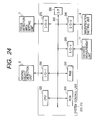
- Fig. 24 shows the arrangement of the system control unit 200.
- the system control unit 200 includes a CPU 220, a ROM 230, a RAM 240, and a bus 300.
- the CPU 220 reads out programs stored in the ROM 230 and operates in accordance with the program procedures. In the course of operation, the CPU 220 holds information required to be temporarily held and information changing in accordance with the situation in the RAM 240.
- An I/O port (1) 250 interfaces the CPU 220 with a moving object detection unit 5.
- I/O ports (3, 4, and 5) 270, 280, and 290 interface the CPU 220 with a focus detection area setting unit 7, a distance measurement unit 11, and a magnification setting unit 9, respectively.
- a communication interface 390 communicates with external apparatuses. For example, the communication interface 390 receives the size of a moving object to be detected from an external apparatus or, when a moving object with a desired size is detected, informs an external apparatus of the detection.
- ROM 230 can be, e.g., a semiconductor memory, an optical disk, a magnetooptical disk, or a magnetic medium.
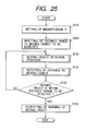
- step S101 the CPU 220 receives a desired magnification D from an external host computer via the communication interface 390.
- the CPU 220 sets the input magnification D in the magnification setting unit 9 via the I/O-5 (290) shown in Fig. 24.
- the magnification setting unit 9 causes a zoom control unit 10 to control a zooming lens motor in accordance with the magnification D and sets the desired magnification D in the apparatus.
- step S102 the CPU 220 receives a distance range L 0 -L 1 (m) to a moving object to be detected from the external host computer via the communication interface 390.
- the CPU 220 holds the input distance range L 0 -L 1 in a predetermined area of the RAM 240.
- L 0 and L 1 represent the distances from an image pickup unit in the optical axis direction (the direction of depth) of a lens and satisfy L 0 ⁇ L 1 . That is, a moving object to be detected is an object in the distance range of L 0 to L 1 from the image pickup unit.
- the flow then advances to step S103, and the CPU 220 starts a loop (steps S103 to 105) of detecting a moving object in the predetermined distance range.
- Step S103 is the same as in the process procedure shown in Fig. 19, so a detailed description thereof will be omitted.
- the flow advances to step S104, and the CPU 220 detects a distance L to a moving object.
- Step S104 is the same as in the process procedure shown in Fig. 20, so a detailed description thereof will be omitted.
- the flow advances to step S105.
- an inside and outside distance range discrimination unit 210 in Fig. 23 checks whether the moving object is in the predetermined distance range by checking whether L 0 ⁇ L ⁇ L 1 . If L 0 ⁇ L ⁇ L 1 , this means that the moving object is in the predetermined distance range, so the flow advances to step S106; if not, this means that no moving object is in the predetermined distance range, so the flow returns to step S103, and the CPU 220 again executes the loop of detecting a moving object in the predetermined distance range. In step S106, the CPU 220 informs the external apparatus of the detection of a moving object in the predetermined distance range via the communication interface 390.
- the CPU 220 completes the procedure of detecting a moving object in a predetermined distance range.
- the predetermined distance range designation method in the fifth embodiment is not restricted to designation of L 0 and L 1 (m).
- the unit of numerical values need not be in meters. That is, it is of course possible to use a value expressed by an 8- or 16-bit code which is used when the distance from a camera to an object to be focused is obtained by using an LUT, as explained earlier as the arrangement of the distance measurement unit 11.
- distance data need not be input from an external host computer via the communication interface 390.
- the video camera main body can include dial switches or ten-key buttons (not shown), and an operator can directly designate data by using these switches or buttons.
- An image pickup lens 12 in the fifth embodiment need not have a zooming function.
- an image pickup lens having no zooming function is used.
- magnification setting unit 9 and the zoom control unit 10 shown in Fig. 23, the I/O-5 (290) shown in Fig. 24, and step S101 shown in Fig. 25 are unnecessary.
- the position and focusing distance of a focusing lens are actually measured in advance to generate data of an LUT in a distance measurement unit 11. Addresses of the LUT are input by using driving pulses of a focusing lens motor.
- a more inexpensive arrangement than in the fifth embodiment is possible, although no variable magnification can be set.
- the distance to a moving object in an image is measured and compared with information pertaining to a predetermined distance range. Consequently, a moving object in the predetermined distance range can be reliably detected.
- the above effect can be achieved with a simpler arrangement by using information regarding focusing control or zoom control in the distance measurement.
Landscapes
- Physics & Mathematics (AREA)
- Engineering & Computer Science (AREA)
- Geometry (AREA)
- Computer Vision & Pattern Recognition (AREA)
- General Physics & Mathematics (AREA)
- Theoretical Computer Science (AREA)
- Length Measuring Devices By Optical Means (AREA)
- Measurement Of Optical Distance (AREA)
- Image Processing (AREA)
- Image Analysis (AREA)
Applications Claiming Priority (6)
| Application Number | Priority Date | Filing Date | Title |
|---|---|---|---|
| JP27423997 | 1997-10-07 | ||
| JP274239/97 | 1997-10-07 | ||
| JP9274239A JPH11112966A (ja) | 1997-10-07 | 1997-10-07 | 動体検出装置、動体検出方法及びコンピュータ読み取り可能な記憶媒体 |
| JP9360704A JPH11196320A (ja) | 1997-12-26 | 1997-12-26 | 動画像処理装置、動画像処理方法及びコンピュータ読み取り可能な記憶媒体 |
| JP360704/97 | 1997-12-26 | ||
| JP36070497 | 1997-12-26 |
Publications (2)
| Publication Number | Publication Date |
|---|---|
| EP0908846A2 true EP0908846A2 (fr) | 1999-04-14 |
| EP0908846A3 EP0908846A3 (fr) | 2000-03-29 |
Family
ID=26550950
Family Applications (1)
| Application Number | Title | Priority Date | Filing Date |
|---|---|---|---|
| EP98307946A Ceased EP0908846A3 (fr) | 1997-10-07 | 1998-09-30 | Méthode et appareil de détection d'un objet en mouvement |
Country Status (2)
| Country | Link |
|---|---|
| US (1) | US20030117516A1 (fr) |
| EP (1) | EP0908846A3 (fr) |
Cited By (3)
| Publication number | Priority date | Publication date | Assignee | Title |
|---|---|---|---|---|
| US6476857B1 (en) | 2000-08-02 | 2002-11-05 | Hitachi, Ltd. | Multi-point monitor camera system |
| EP1128666A3 (fr) * | 2000-02-15 | 2003-07-16 | Matsushita Electric Industrial Co., Ltd. | Appareil pour surveiller des objets |
| EP1968012A3 (fr) * | 1999-11-16 | 2008-12-03 | FUJIFILM Corporation | Appareil de traitement d'images, procédé de traitement d'images et support d'enregistrement |
Families Citing this family (17)
| Publication number | Priority date | Publication date | Assignee | Title |
|---|---|---|---|---|
| JP4531897B2 (ja) * | 1999-12-27 | 2010-08-25 | パナソニック株式会社 | 人物追跡装置、人物追跡方法及びそのプログラムを記録した記録媒体 |
| JP3893829B2 (ja) * | 2000-01-14 | 2007-03-14 | 富士ゼロックス株式会社 | 画像処理装置および画像処理方法ならびに画像形成装置 |
| JP3860552B2 (ja) * | 2003-03-25 | 2006-12-20 | 富士通株式会社 | 撮影装置 |
| JP4525089B2 (ja) * | 2004-01-27 | 2010-08-18 | フジノン株式会社 | オートフォーカスシステム |
| US7982774B2 (en) * | 2004-09-13 | 2011-07-19 | Sony Corporation | Image processing apparatus and image processing method |
| JP2006234545A (ja) * | 2005-02-24 | 2006-09-07 | Seiko Epson Corp | 静止画像撮像装置 |
| JP2007006165A (ja) | 2005-06-24 | 2007-01-11 | Fujifilm Holdings Corp | 撮像装置、撮像方法、及び撮像プログラム |
| JP4745769B2 (ja) * | 2005-09-13 | 2011-08-10 | キヤノン株式会社 | カメラ雲台装置 |
| US20080266444A1 (en) * | 2007-04-27 | 2008-10-30 | Micron Technology, Inc. | Method, apparatus, and system for continuous autofocusing |
| JP5517435B2 (ja) * | 2008-10-22 | 2014-06-11 | キヤノン株式会社 | 自動合焦装置および自動合焦方法、ならびに、撮像装置 |
| JP5347802B2 (ja) * | 2009-07-27 | 2013-11-20 | ソニー株式会社 | 構図制御装置、撮像システム、構図制御方法、プログラム |
| JP5178797B2 (ja) * | 2010-09-13 | 2013-04-10 | キヤノン株式会社 | 表示制御装置及び表示制御方法 |
| TW201216711A (en) * | 2010-10-12 | 2012-04-16 | Hon Hai Prec Ind Co Ltd | TOF image capturing device and image monitoring method using the TOF image capturing device |
| TWI466545B (zh) * | 2010-10-12 | 2014-12-21 | Hon Hai Prec Ind Co Ltd | 攝影機裝置及利用其進行影像監控的方法 |
| JP5834232B2 (ja) * | 2011-01-17 | 2015-12-16 | パナソニックIpマネジメント株式会社 | 撮像画像認識装置、撮像画像認識システム及び撮像画像認識方法 |
| DE102013224704A1 (de) * | 2013-12-03 | 2015-06-03 | Robert Bosch Gmbh | Verfahren zur automatischen Fokussierung einer Kamera |
| CN109479082B (zh) * | 2016-12-21 | 2021-10-15 | 华为技术有限公司 | 图象处理方法及装置 |
Citations (4)
| Publication number | Priority date | Publication date | Assignee | Title |
|---|---|---|---|---|
| US3988533A (en) * | 1974-09-30 | 1976-10-26 | Video Tek, Inc. | Video-type universal motion and intrusion detection system |
| US4992866A (en) * | 1989-06-29 | 1991-02-12 | Morgan Jack B | Camera selection and positioning system and method |
| EP0525482A2 (fr) * | 1991-07-31 | 1993-02-03 | Sensormatic Electronics Corporation | Dispositif de surveillance avec commande de la caméra et de l'assemblage des lentilles |
| US5331419A (en) * | 1991-03-26 | 1994-07-19 | Kyocera Corporation | Size display system for electronic camera |
Family Cites Families (10)
| Publication number | Priority date | Publication date | Assignee | Title |
|---|---|---|---|---|
| JPS6446875A (en) * | 1987-08-17 | 1989-02-21 | Toshiba Corp | Object discriminating device |
| JPH0695008B2 (ja) * | 1987-12-11 | 1994-11-24 | 株式会社東芝 | 監視装置 |
| US5111288A (en) * | 1988-03-02 | 1992-05-05 | Diamond Electronics, Inc. | Surveillance camera system |
| US5134472A (en) * | 1989-02-08 | 1992-07-28 | Kabushiki Kaisha Toshiba | Moving object detection apparatus and method |
| US5034986A (en) * | 1989-03-01 | 1991-07-23 | Siemens Aktiengesellschaft | Method for detecting and tracking moving objects in a digital image sequence having a stationary background |
| US5164827A (en) * | 1991-08-22 | 1992-11-17 | Sensormatic Electronics Corporation | Surveillance system with master camera control of slave cameras |
| JP3049672B2 (ja) * | 1991-12-26 | 2000-06-05 | キヤノン株式会社 | 画像処理方法及び装置 |
| JP3026698B2 (ja) * | 1993-05-27 | 2000-03-27 | キヤノン株式会社 | 画像処理方法及びその装置 |
| JP3279479B2 (ja) * | 1996-05-31 | 2002-04-30 | 株式会社日立国際電気 | 映像監視方法及び装置 |
| US6359644B1 (en) * | 1998-09-01 | 2002-03-19 | Welch Allyn, Inc. | Measurement system for video colposcope |
-
1998
- 1998-09-30 EP EP98307946A patent/EP0908846A3/fr not_active Ceased
- 1998-10-01 US US09/164,624 patent/US20030117516A1/en not_active Abandoned
Patent Citations (4)
| Publication number | Priority date | Publication date | Assignee | Title |
|---|---|---|---|---|
| US3988533A (en) * | 1974-09-30 | 1976-10-26 | Video Tek, Inc. | Video-type universal motion and intrusion detection system |
| US4992866A (en) * | 1989-06-29 | 1991-02-12 | Morgan Jack B | Camera selection and positioning system and method |
| US5331419A (en) * | 1991-03-26 | 1994-07-19 | Kyocera Corporation | Size display system for electronic camera |
| EP0525482A2 (fr) * | 1991-07-31 | 1993-02-03 | Sensormatic Electronics Corporation | Dispositif de surveillance avec commande de la caméra et de l'assemblage des lentilles |
Non-Patent Citations (2)
| Title |
|---|
| HORTON R.D.: "A target cueing and tracking system (TCATS) for smart video processing", PROCEEDINGS. IEEE 1990 INTERNATIONAL CARNAHAN CONFERENCE ON SECURITY TECHNOLOGY: CRIME COUNTERMEASURES, 10-12 OCT. 1990, LEXINGTON, KY, USA, 10 October 1990 (1990-10-10), IEEE, NEW YORK, NY, USA, pages 68 - 72, XP010079318 * |
| KISSOCK P.S.; PRITCHARD D.A.: "A proposed protocol for remote control of automated assessment devices", PROCEEDINGS OF IEEE INTERNATIONAL CARNAHAN CONFERENCE ON SECURITY TECHNOLOGY, 2-4 OCT. 1996, LEXINGTON, KY, USA, 2 October 1996 (1996-10-02), IEEE, NEW YORK, NY, USA, pages 115 - 119, XP010199876 * |
Cited By (4)
| Publication number | Priority date | Publication date | Assignee | Title |
|---|---|---|---|---|
| EP1968012A3 (fr) * | 1999-11-16 | 2008-12-03 | FUJIFILM Corporation | Appareil de traitement d'images, procédé de traitement d'images et support d'enregistrement |
| US7570281B1 (en) | 1999-11-16 | 2009-08-04 | Fujifilm Corporation | Image processing apparatus and method for detecting a main subject to be photographed |
| EP1128666A3 (fr) * | 2000-02-15 | 2003-07-16 | Matsushita Electric Industrial Co., Ltd. | Appareil pour surveiller des objets |
| US6476857B1 (en) | 2000-08-02 | 2002-11-05 | Hitachi, Ltd. | Multi-point monitor camera system |
Also Published As
| Publication number | Publication date |
|---|---|
| EP0908846A3 (fr) | 2000-03-29 |
| US20030117516A1 (en) | 2003-06-26 |
Similar Documents
| Publication | Publication Date | Title |
|---|---|---|
| EP0908846A2 (fr) | Méthode et appareil de détection d'un objet en mouvement | |
| EP1343332B1 (fr) | Système d'examen des caractéristiques d'une image stéréoscopique | |
| US5877809A (en) | Method of automatic object detection in image | |
| US5602584A (en) | Apparatus for producing a panoramic image using a plurality of optical systems | |
| US7834907B2 (en) | Image-taking apparatus and image processing method | |
| JP3804916B2 (ja) | 撮像システムとその画像データ制御に用いられるプログラムおよびその撮像システムにおける撮像画像の歪み補正方法とその手順を記憶させた記憶媒体 | |
| JPH11261868A (ja) | 魚眼レンズカメラ装置及びその画像歪み補正方法及び画像抽出方法 | |
| JP2003244521A (ja) | 情報処理方法、装置および記録媒体 | |
| KR100341265B1 (ko) | 움직임벡터검출장치및고체촬상장치 | |
| KR20110007426A (ko) | 감시 카메라, 그 제어방법 및 이를 실행하기 위한 프로그램을 저장한 기록매체 | |
| JPH10145667A (ja) | 撮像装置 | |
| JP2003304561A (ja) | ステレオ画像処理装置 | |
| US20050105822A1 (en) | Variable distortion aberration image pickup device | |
| JP2001285701A (ja) | 車載カメラ装置 | |
| JPH11112966A (ja) | 動体検出装置、動体検出方法及びコンピュータ読み取り可能な記憶媒体 | |
| KR102156998B1 (ko) | 비디오 시퀀스에서 모션을 감지하기 위한 방법 | |
| JPH11196320A (ja) | 動画像処理装置、動画像処理方法及びコンピュータ読み取り可能な記憶媒体 | |
| KR101341632B1 (ko) | 줌 카메라의 광축 오차 보상 시스템, 그 보상 방법 | |
| CN117714863A (zh) | 拍摄方法及其相关设备 | |
| US20070030377A1 (en) | Imaging device | |
| JPH11223516A (ja) | 3次元画像撮像装置 | |
| EP4708897A1 (fr) | Appareil de commande de capture d'image, procédé de commande de capture d'image, système de capture d'image, programme informatique et support de stockage | |
| JP3066594U (ja) | 画像変換装置 | |
| JP3446471B2 (ja) | ステレオ画像処理装置 | |
| KR101353473B1 (ko) | 감시 카메라, 그 제어방법 및 이를 실행하기 위한 프로그램을 저장한 기록매체 |
Legal Events
| Date | Code | Title | Description |
|---|---|---|---|
| PUAI | Public reference made under article 153(3) epc to a published international application that has entered the european phase |
Free format text: ORIGINAL CODE: 0009012 |
|
| AK | Designated contracting states |
Kind code of ref document: A2 Designated state(s): DE FR GB |
|
| AX | Request for extension of the european patent |
Free format text: AL;LT;LV;MK;RO;SI |
|
| PUAL | Search report despatched |
Free format text: ORIGINAL CODE: 0009013 |
|
| AK | Designated contracting states |
Kind code of ref document: A3 Designated state(s): AT BE CH CY DE DK ES FI FR GB GR IE IT LI LU MC NL PT SE |
|
| AX | Request for extension of the european patent |
Free format text: AL;LT;LV;MK;RO;SI |
|
| RIC1 | Information provided on ipc code assigned before grant |
Free format text: 7G 06T 7/20 A, 7G 06T 7/60 B |
|
| 17P | Request for examination filed |
Effective date: 20000817 |
|
| AKX | Designation fees paid |
Free format text: DE FR GB |
|
| 17Q | First examination report despatched |
Effective date: 20010703 |
|
| STAA | Information on the status of an ep patent application or granted ep patent |
Free format text: STATUS: THE APPLICATION HAS BEEN REFUSED |
|
| 18R | Application refused |
Effective date: 20060526 |