EP0908963B1 - Akkumulator mit alkalischem Elektrolyten, insbesondere des Typs Nickel-Cadmium oder Nickel/Metallhydrid - Google Patents
Akkumulator mit alkalischem Elektrolyten, insbesondere des Typs Nickel-Cadmium oder Nickel/Metallhydrid Download PDFInfo
- Publication number
- EP0908963B1 EP0908963B1 EP98402291A EP98402291A EP0908963B1 EP 0908963 B1 EP0908963 B1 EP 0908963B1 EP 98402291 A EP98402291 A EP 98402291A EP 98402291 A EP98402291 A EP 98402291A EP 0908963 B1 EP0908963 B1 EP 0908963B1
- Authority
- EP
- European Patent Office
- Prior art keywords
- layer
- separator
- fibers
- storage cell
- fact
- Prior art date
- Legal status (The legal status is an assumption and is not a legal conclusion. Google has not performed a legal analysis and makes no representation as to the accuracy of the status listed.)
- Expired - Lifetime
Links
Images
Classifications
-
- H—ELECTRICITY
- H01—ELECTRIC ELEMENTS
- H01M—PROCESSES OR MEANS, e.g. BATTERIES, FOR THE DIRECT CONVERSION OF CHEMICAL ENERGY INTO ELECTRICAL ENERGY
- H01M10/00—Secondary cells; Manufacture thereof
- H01M10/24—Alkaline accumulators
- H01M10/28—Construction or manufacture
- H01M10/286—Cells or batteries with wound or folded electrodes
-
- H—ELECTRICITY
- H01—ELECTRIC ELEMENTS
- H01M—PROCESSES OR MEANS, e.g. BATTERIES, FOR THE DIRECT CONVERSION OF CHEMICAL ENERGY INTO ELECTRICAL ENERGY
- H01M50/00—Constructional details or processes of manufacture of the non-active parts of electrochemical cells other than fuel cells, e.g. hybrid cells
- H01M50/40—Separators; Membranes; Diaphragms; Spacing elements inside cells
- H01M50/409—Separators, membranes or diaphragms characterised by the material
- H01M50/411—Organic material
- H01M50/414—Synthetic resins, e.g. thermoplastics or thermosetting resins
-
- H—ELECTRICITY
- H01—ELECTRIC ELEMENTS
- H01M—PROCESSES OR MEANS, e.g. BATTERIES, FOR THE DIRECT CONVERSION OF CHEMICAL ENERGY INTO ELECTRICAL ENERGY
- H01M50/00—Constructional details or processes of manufacture of the non-active parts of electrochemical cells other than fuel cells, e.g. hybrid cells
- H01M50/40—Separators; Membranes; Diaphragms; Spacing elements inside cells
- H01M50/409—Separators, membranes or diaphragms characterised by the material
- H01M50/411—Organic material
- H01M50/414—Synthetic resins, e.g. thermoplastics or thermosetting resins
- H01M50/417—Polyolefins
-
- H—ELECTRICITY
- H01—ELECTRIC ELEMENTS
- H01M—PROCESSES OR MEANS, e.g. BATTERIES, FOR THE DIRECT CONVERSION OF CHEMICAL ENERGY INTO ELECTRICAL ENERGY
- H01M50/00—Constructional details or processes of manufacture of the non-active parts of electrochemical cells other than fuel cells, e.g. hybrid cells
- H01M50/40—Separators; Membranes; Diaphragms; Spacing elements inside cells
- H01M50/409—Separators, membranes or diaphragms characterised by the material
- H01M50/44—Fibrous material
-
- H—ELECTRICITY
- H01—ELECTRIC ELEMENTS
- H01M—PROCESSES OR MEANS, e.g. BATTERIES, FOR THE DIRECT CONVERSION OF CHEMICAL ENERGY INTO ELECTRICAL ENERGY
- H01M50/00—Constructional details or processes of manufacture of the non-active parts of electrochemical cells other than fuel cells, e.g. hybrid cells
- H01M50/40—Separators; Membranes; Diaphragms; Spacing elements inside cells
- H01M50/409—Separators, membranes or diaphragms characterised by the material
- H01M50/449—Separators, membranes or diaphragms characterised by the material having a layered structure
-
- H—ELECTRICITY
- H01—ELECTRIC ELEMENTS
- H01M—PROCESSES OR MEANS, e.g. BATTERIES, FOR THE DIRECT CONVERSION OF CHEMICAL ENERGY INTO ELECTRICAL ENERGY
- H01M50/00—Constructional details or processes of manufacture of the non-active parts of electrochemical cells other than fuel cells, e.g. hybrid cells
- H01M50/40—Separators; Membranes; Diaphragms; Spacing elements inside cells
- H01M50/489—Separators, membranes, diaphragms or spacing elements inside the cells, characterised by their physical properties, e.g. swelling degree, hydrophilicity or shut down properties
-
- H—ELECTRICITY
- H01—ELECTRIC ELEMENTS
- H01M—PROCESSES OR MEANS, e.g. BATTERIES, FOR THE DIRECT CONVERSION OF CHEMICAL ENERGY INTO ELECTRICAL ENERGY
- H01M10/00—Secondary cells; Manufacture thereof
- H01M10/34—Gastight accumulators
- H01M10/345—Gastight metal hydride accumulators
-
- Y—GENERAL TAGGING OF NEW TECHNOLOGICAL DEVELOPMENTS; GENERAL TAGGING OF CROSS-SECTIONAL TECHNOLOGIES SPANNING OVER SEVERAL SECTIONS OF THE IPC; TECHNICAL SUBJECTS COVERED BY FORMER USPC CROSS-REFERENCE ART COLLECTIONS [XRACs] AND DIGESTS
- Y02—TECHNOLOGIES OR APPLICATIONS FOR MITIGATION OR ADAPTATION AGAINST CLIMATE CHANGE
- Y02E—REDUCTION OF GREENHOUSE GAS [GHG] EMISSIONS, RELATED TO ENERGY GENERATION, TRANSMISSION OR DISTRIBUTION
- Y02E60/00—Enabling technologies; Technologies with a potential or indirect contribution to GHG emissions mitigation
- Y02E60/10—Energy storage using batteries
-
- Y—GENERAL TAGGING OF NEW TECHNOLOGICAL DEVELOPMENTS; GENERAL TAGGING OF CROSS-SECTIONAL TECHNOLOGIES SPANNING OVER SEVERAL SECTIONS OF THE IPC; TECHNICAL SUBJECTS COVERED BY FORMER USPC CROSS-REFERENCE ART COLLECTIONS [XRACs] AND DIGESTS
- Y02—TECHNOLOGIES OR APPLICATIONS FOR MITIGATION OR ADAPTATION AGAINST CLIMATE CHANGE
- Y02P—CLIMATE CHANGE MITIGATION TECHNOLOGIES IN THE PRODUCTION OR PROCESSING OF GOODS
- Y02P70/00—Climate change mitigation technologies in the production process for final industrial or consumer products
- Y02P70/50—Manufacturing or production processes characterised by the final manufactured product
Definitions
- the present invention relates to an alkaline electrolyte accumulator, in particular of the Nickel-Cadmium (Ni-Cd) or Nickel-Metal hydrurable (Ni-MH) type, and in particular a separator for such an accumulator.
- an alkaline electrolyte accumulator in particular of the Nickel-Cadmium (Ni-Cd) or Nickel-Metal hydrurable (Ni-MH) type, and in particular a separator for such an accumulator.
- Ni-Cd batteries have been used for a very long time as autonomous energy source. They are known to have good retention charging, i.e. when stored in the charged state, their capacity slowly decreases. The charge lost by a completely Ni-Cd accumulator charged is around 20% in 7 days at 40 ° C.
- Ni-MH battery has a volume capacity greater than that of the Ni-Cd accumulator, which means that a format accumulator given will have greater autonomy if it contains a metal that can be hydrurized rather than a negative cadmium electrode.
- the Ni-MH accumulator has a strong self-discharge, which represents a very penalizing problem for the user.
- the charge lost by a Ni-MH accumulator stored in the state fully charged is about twice as large as for a Ni-Cd accumulator, i.e. 40% in 7 days at 40 ° C. This poor result is due to fact that the MH electrode once charged has a reducing character higher than that of the Cd electrode.
- Self-discharge is generally partly attributed to shuttles nitrogenous.
- the ammonia and the nitrites present in the accumulator oxidize to nitrates on the charged positive electrode, which results in to discharge it.
- the nitrates and nitrites are reduced to ammonia on the charged negative electrode, which has the consequence of discharging it also.
- a polyolefin separator presents difficulties of use to because of its strong hydrophobicity.
- it can be oxidized by fluorination treatment (see EP-0 696 822), by corona discharge (see JP-A-07 02 583) or by other methods (see JP-A-07 192 714), or grafted with hydrophilic monomers. You can also introduce a wetting agent in the electrolyte.
- a polyethylene fiber separator is chemically stable in the electrolyte used, does not introduce additional nitrogenous species into the accumulator, but has no effect on the nitrogenous shuttles due to the impurities provided by the other components of the accumulator.
- the use of a polyethylene separator therefore does not significantly reduce the self-discharge of Ni-MH accumulators.
- Another solution is to use a separator composed of a mixture of fibers made exclusively of polypropylene, called fibers non-binding, and polypropylene fibers covered with a sheath polyethylene, called binder fibers.
- the polyethylene melting (the melting point of which is lower than the polypropylene melting temperature) allows the sheathed fibers to bond to unsheathed fibers.
- This separator is able to fix a certain amount ammonia and therefore limit the amount of impurities feeding the shuttles nitrogenous. However, the amount of ammonia that can be fixed by such a separator is less than the amount of nitrogenous species present in the accumulator.
- the best solution to reduce the self-discharge of accumulators Ni-MH is to use a separator exclusively made of polypropylene which is capable of fixing more ammonia than a separator consisting of a blend of polypropylene and polyethylene. It can thus block in the form of ammonia all the nitrogenous impurities present in the accumulator and introduced by the constituents used. The nitrogen shuttles are therefore completely deleted and the associated self-discharge.
- the present invention aims to provide a spiral accumulator to alkaline electrolyte comprising a separator which simultaneously has the ability to reduce self-discharge and good mechanical strength.
- the object of the present invention is a spiral accumulator with electrolyte alkaline, in particular of the Nickel-Cadmium or Nickel-Metal hydrurable type, comprising at least one positive electrode and one negative electrode placed on either side of a non-woven separator made of fibers exclusively polypropylene, characterized in that said separator comprises a first and second layers superimposed, said first layer being obtained by the so-called "spun-bond" spinning process serving as support, and said second layer being obtained by needling fibers on said first layer, the needling having interlaced the fibers of the second layer and having linked them to those of said first layer.
- the fibers of the two layers have the parameters following: the fibers of said first layer have a diameter of between 10 and 20 ⁇ m and those of said second layer a diameter between 2 and 15 ⁇ m; the fibers of said second layer have a length of between 5 mm and 40 mm.
- the surface mass of said first layer and that of said second layer are between 15 and 80 g / m 2 .
- the surface mass of said separator is between 30 and 100 g / m 2 .
- the thickness of said separator is between 80 ⁇ m and 400 ⁇ m, the thickness of said first layer being between 20 and 80% of the thickness of this separator.
- Said separator is grafted with a vinyl monomer chosen from preferably from acrylic acid and metacrylic acid.
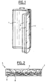
- a spiral accumulator 1 of the Ni-Cd type, visible in FIG. 1, is constructed, consisting of a positive electrode 3 whose active material is nickel hydroxide and a negative electrode 2 whose active material is l 'cadmium hydroxide. These two electrodes are separated by a separator 4 made of polyamide. The whole is spiraled into an AA-size cup and filled with an electrolyte composed of a mixture of potassium hydroxide, sodium hydroxide and lithium hydroxide. Such an accumulator is charged and then discharged twice. After the third charge, it is stored at free potential for 7 days at 40 ° C. After returning to ambient temperature, it is completely discharged at a rate of C / 5 in order to determine its residual capacity.
- Capacity loss is defined as the difference between the discharged capacity obtained during the second discharge and the discharged capacity obtained after standing for 7 days at 40 ° C and divided by the discharged capacity obtained during the second discharge. In the case of this accumulator, the loss of capacity is 23%.
- Ni-MH type accumulator identical to the accumulator of Example 1 is constructed except as regards the negative cadmium electrode replaced by a conventional hydrurable alloy electrode. Such an accumulator is charged and then discharged twice. After the third charge, it is stored at free potential for 7 days at 40 ° C. After returning to ambient temperature, it is completely discharged at a rate of C / 5 in order to determine its residual capacity.
- the loss of capacity is defined in the same way as in Example 1. In the case of the present accumulator, the loss of capacity is 46%.
- Ni-MH type accumulator is constructed as described in Example 2. However, the polyamide separator 4 is replaced by a separator made of fine polyethylene fibers made hydrophilic by an oxidation treatment which can be a corona discharge or a treatment fluorination under oxygen atmosphere. The self-discharge of this accumulator is tested as described in Example 2. In the case of this accumulator, the loss of capacity is 45%.
- Ni-MH type accumulator is constructed as described in Example 2.
- the polyamide separator 4 is replaced by a polyolefin separator, consisting of a mixture of polyethylene and polypropylene fibers, and made hydrophilic by grafting d acrylic acid.
- the self-discharge of this accumulator is tested as described in Example 2.
- the loss of capacity is 48%.
- An identical result is obtained if the grafting is carried out with metacrylic acid.
- Example 5 according to the invention :
- Ni-Cd type accumulator is constructed as described in Example 1. But the polyamide separator 4 is replaced by a separator according to the invention, "visible in schematic section in FIG. 2.
- This separator 5 comprises a first layer 6 of fibers 8 of polypropylene with an average diameter of 15 ⁇ m produced by the "spun bond" process, and a second layer 7 of polypropylene fibers 9 with an average diameter of 10 ⁇ m and average length 30 mm, produced by the needling process using traditional needles or water needles.
- a method is described in particular in the article published in International Nonwovens Bulletin 1/90 (21. Internationales Kolloquium über Nonwovens, Brno, 8-10 November 1989); "Neue Maschinenbuchen für Spunlaced Nonwovensnch” - pages 1-8.
- the overall thickness of the separator 5 is 150 ⁇ m, of which approximately 40% corresponds to the thickness of the first layer.
- the separator is grafted with acrylic acid.
- acrylic acid For this it is impregnated with an aqueous solution containing acrylic acid and a photoinitiator, agent intended to increase the sensitivity of the polymer to rays ultra-violet; then it is subjected to ultraviolet radiation, rinsed with water deionized and dried.
- the accumulator is subjected to the same test as in Example 1 and the loss of measured capacity is no more than 18%.
- the grafting can be carried out with metacrylic acid and the same result.
- Ni-MH type accumulator is constructed as described in Example 2, replacing the polyamide separator 4 by the separator 5 according to the invention described in Example 5.
- the accumulator is subjected to the same test as in Example 2, and the loss of capacity measured is no more than 22%.
- a separator according to the invention retains the good mechanical properties of known separators of the "spun bond” type, while being much less vulnerable to short circuits.
Landscapes
- Chemical & Material Sciences (AREA)
- Chemical Kinetics & Catalysis (AREA)
- Electrochemistry (AREA)
- General Chemical & Material Sciences (AREA)
- Engineering & Computer Science (AREA)
- Manufacturing & Machinery (AREA)
- Cell Separators (AREA)
- Secondary Cells (AREA)
Claims (8)
- Spiralgewickelter Akkumulator mit alkalischem Elektrolyten, insbesondere vom Typ Nickel-Kadmium oder Nickel-Metallhydrid, mit wenigstens einer positiven Elektrode und einer negativen-Elektrode, die sich beiderseits eines nichtgewebten Separators befinden, der ausschließlich aus Polypropylenfasern gebildet ist,
dadurch gekennzeichnet, dass der Separator eine erste und eine zweite übereinanderliegende Lage aufweist, wobei die durch das "spun-bond" genannte Spinnverfahren gewonnene erste Lage als Träger dient, und die zweite Lage durch Nadelung der Fasern auf die erste Lage gewonnen wird, wobei bei der Nadelung die Fasern der zweiten Lage miteinander verwoben und diese mit denen der ersten Lage verknüpft werden. - Akkumulator nach Anspruch 1,
dadurch gekennzeichnet, dass die Fasern der ersten Lage einen Durchmesser zwischen 10 und 20 um und die der zweiten Lage einen Durchmesser zwischen 2 und 15 µm haben. - Akkumulator nach Anspruch 2,
dadurch gekennzeichnet, dass die Fasern der zweiten Lage eine Länge zwischen 5 mm und 40 mm haben. - Akkumulator nach einem der Ansprüche 1 bis 3,
dadurch gekennzeichnet, dass die flächenbezogene Masse der ersten Lage und die der zweiten Lage zwischen 15 und 80 g/m2 liegt. - Akkumulator nach einem der Ansprüche 1 bis 4,
dadurch gekennzeichnet, dass die flächenbezogene Masse des Separators zwischen 30 und 100 g/m2 liegt. - Akkumulator nach einem der Ansprüche 1 bis 5,
dadurch gekennzeichnet, dass die Stärke des Separators zwischen 80 um und 400 um liegt, wobei die Stärke der ersten Lage zwischen 20 und 80% der Stärke des Separators beträgt. - Akkumulator nach einem der vorhergehenden Ansprüche,
dadurch gekennzeichnet, dass der Separator durch ein Vinylmonomer veredelt ist. - Akkumulator nach Anspruch 7,
dadurch gekennzeichnet, dass das Vinylmonomer aus Acrylsäure und Metacrylsäure gewählt ist.
Applications Claiming Priority (2)
| Application Number | Priority Date | Filing Date | Title |
|---|---|---|---|
| FR9712510 | 1997-10-07 | ||
| FR9712510A FR2769408B1 (fr) | 1997-10-07 | 1997-10-07 | Accumulateur a electrolyte alcalin, notamment de type nickel-cadmium ou nickel-metal hydrurable |
Publications (2)
| Publication Number | Publication Date |
|---|---|
| EP0908963A1 EP0908963A1 (de) | 1999-04-14 |
| EP0908963B1 true EP0908963B1 (de) | 2001-11-21 |
Family
ID=9511936
Family Applications (1)
| Application Number | Title | Priority Date | Filing Date |
|---|---|---|---|
| EP98402291A Expired - Lifetime EP0908963B1 (de) | 1997-10-07 | 1998-09-17 | Akkumulator mit alkalischem Elektrolyten, insbesondere des Typs Nickel-Cadmium oder Nickel/Metallhydrid |
Country Status (5)
| Country | Link |
|---|---|
| US (1) | US5939222A (de) |
| EP (1) | EP0908963B1 (de) |
| JP (1) | JPH11162438A (de) |
| DE (1) | DE69803263T2 (de) |
| FR (1) | FR2769408B1 (de) |
Families Citing this family (3)
| Publication number | Priority date | Publication date | Assignee | Title |
|---|---|---|---|---|
| KR100527322B1 (ko) * | 1997-05-06 | 2006-01-27 | 소니 가부시끼 가이샤 | 폴리머겔전해질형성용시트,이를사용한폴리머겔전해질및그의제법 |
| US7063917B2 (en) | 2001-02-21 | 2006-06-20 | Ahlstrom Mount Holly Springs, Llc | Laminated battery separator material |
| WO2008047542A1 (fr) * | 2006-09-28 | 2008-04-24 | Japan Vilene Company, Ltd. | Séparateur de batterie alcaline, procédé de production de celui-ci et batteries alcalines |
Family Cites Families (7)
| Publication number | Priority date | Publication date | Assignee | Title |
|---|---|---|---|---|
| NL274822A (de) * | 1961-06-12 | |||
| US3330702A (en) * | 1962-03-20 | 1967-07-11 | Yardney International Corp | Battery separator |
| JPS60170159A (ja) * | 1984-02-14 | 1985-09-03 | Matsushita Electric Ind Co Ltd | 密閉形アルカリ蓄電池 |
| US5176968A (en) * | 1990-12-27 | 1993-01-05 | Duracell Inc. | Electrochemical cell |
| US5492781A (en) * | 1994-01-18 | 1996-02-20 | Pall Corporation | Battery separators |
| EP0680107B1 (de) * | 1994-04-15 | 1998-07-22 | Kabushiki Kaisha Toshiba | Nickelwasserstoff Sekundärbatterie |
| US5685773A (en) * | 1995-10-06 | 1997-11-11 | Fmc Corporation | Adjustable four-weight shaker head |
-
1997
- 1997-10-07 FR FR9712510A patent/FR2769408B1/fr not_active Expired - Fee Related
- 1997-10-14 US US08/943,316 patent/US5939222A/en not_active Expired - Fee Related
-
1998
- 1998-09-17 EP EP98402291A patent/EP0908963B1/de not_active Expired - Lifetime
- 1998-09-17 DE DE69803263T patent/DE69803263T2/de not_active Expired - Lifetime
- 1998-10-05 JP JP10282183A patent/JPH11162438A/ja active Pending
Also Published As
| Publication number | Publication date |
|---|---|
| FR2769408B1 (fr) | 1999-12-10 |
| EP0908963A1 (de) | 1999-04-14 |
| JPH11162438A (ja) | 1999-06-18 |
| FR2769408A1 (fr) | 1999-04-09 |
| US5939222A (en) | 1999-08-17 |
| DE69803263D1 (de) | 2002-02-21 |
| DE69803263T2 (de) | 2002-08-08 |
Similar Documents
| Publication | Publication Date | Title |
|---|---|---|
| US6878484B2 (en) | Separator for secondary battery and method for producing the same | |
| US20060194100A1 (en) | Battery separator and battery comprising same | |
| KR19980081465A (ko) | 알칼리 전지용 세퍼레이터 및 그의 제조방법 | |
| FR2486312A1 (fr) | Absorbeur d'electrolyte pour accumulateur alcalin | |
| EP0587682B2 (de) | Durch nassverfahren hergestellte bahn und ihre verwendung | |
| EP0834942B1 (de) | Sekundärbatterie mit alkalischem Elektrolyten | |
| EP0908963B1 (de) | Akkumulator mit alkalischem Elektrolyten, insbesondere des Typs Nickel-Cadmium oder Nickel/Metallhydrid | |
| KR100456709B1 (ko) | 알칼리전지용격리판및그의제조방법 | |
| JP2006222083A (ja) | 不織布、繊維および電気化学的電池 | |
| EP0820108A1 (de) | Separator für Akkumulator mit spiralförmig gewickelten Elektroden und alkalischen Elektrolyten | |
| JP3366412B2 (ja) | アルカリ電池用セパレータ | |
| JP4139454B2 (ja) | アルカリ電池用セパレータ及びその製法 | |
| JP3219323B2 (ja) | 電池用セパレータ | |
| JP2001283818A (ja) | アルカリ電池用セパレータ及びアルカリ電池 | |
| JP3784496B2 (ja) | アルカリ電池用セパレータ | |
| JP2002367591A (ja) | アルカリ電池用セパレータ | |
| JP4560227B2 (ja) | 電池用セパレータ | |
| JPH11288702A (ja) | アルカリ電池用セパレータ | |
| JP3114082B2 (ja) | アルカリ電池用セパレータおよびこれを用いたアルカリ蓄電池 | |
| JPH1021894A (ja) | アルカリ電池用セパレータ | |
| JP2001143681A (ja) | 電池用セパレータ及びその製造方法 | |
| JP2002319387A (ja) | アルカリ電池用セパレータ | |
| CN101113551A (zh) | 具有高化学和热耐抗性和较好均匀性的用于碱性蓄电池隔片的无纺布 | |
| JP2001291505A (ja) | アルカリ電池用セパレータ及びアルカリ電池 | |
| JP2002008619A (ja) | 電池用セパレータ |
Legal Events
| Date | Code | Title | Description |
|---|---|---|---|
| PUAI | Public reference made under article 153(3) epc to a published international application that has entered the european phase |
Free format text: ORIGINAL CODE: 0009012 |
|
| AK | Designated contracting states |
Kind code of ref document: A1 Designated state(s): DE FR GB |
|
| AX | Request for extension of the european patent |
Free format text: AL;LT;LV;MK;RO;SI |
|
| 17P | Request for examination filed |
Effective date: 19991014 |
|
| AKX | Designation fees paid |
Free format text: DE FR GB |
|
| GRAG | Despatch of communication of intention to grant |
Free format text: ORIGINAL CODE: EPIDOS AGRA |
|
| 17Q | First examination report despatched |
Effective date: 20010227 |
|
| GRAG | Despatch of communication of intention to grant |
Free format text: ORIGINAL CODE: EPIDOS AGRA |
|
| GRAH | Despatch of communication of intention to grant a patent |
Free format text: ORIGINAL CODE: EPIDOS IGRA |
|
| GRAH | Despatch of communication of intention to grant a patent |
Free format text: ORIGINAL CODE: EPIDOS IGRA |
|
| GRAH | Despatch of communication of intention to grant a patent |
Free format text: ORIGINAL CODE: EPIDOS IGRA |
|
| GRAA | (expected) grant |
Free format text: ORIGINAL CODE: 0009210 |
|
| AK | Designated contracting states |
Kind code of ref document: B1 Designated state(s): DE FR GB |
|
| GBT | Gb: translation of ep patent filed (gb section 77(6)(a)/1977) |
Effective date: 20011121 |
|
| REG | Reference to a national code |
Ref country code: GB Ref legal event code: IF02 |
|
| REF | Corresponds to: |
Ref document number: 69803263 Country of ref document: DE Date of ref document: 20020221 |
|
| PLBE | No opposition filed within time limit |
Free format text: ORIGINAL CODE: 0009261 |
|
| STAA | Information on the status of an ep patent application or granted ep patent |
Free format text: STATUS: NO OPPOSITION FILED WITHIN TIME LIMIT |
|
| 26N | No opposition filed | ||
| REG | Reference to a national code |
Ref country code: GB Ref legal event code: 732E |
|
| REG | Reference to a national code |
Ref country code: FR Ref legal event code: TP |
|
| PGFP | Annual fee paid to national office [announced via postgrant information from national office to epo] |
Ref country code: GB Payment date: 20090922 Year of fee payment: 12 |
|
| PGFP | Annual fee paid to national office [announced via postgrant information from national office to epo] |
Ref country code: DE Payment date: 20090922 Year of fee payment: 12 |
|
| REG | Reference to a national code |
Ref country code: FR Ref legal event code: ST Effective date: 20100531 |
|
| PG25 | Lapsed in a contracting state [announced via postgrant information from national office to epo] |
Ref country code: FR Free format text: LAPSE BECAUSE OF NON-PAYMENT OF DUE FEES Effective date: 20090930 |
|
| GBPC | Gb: european patent ceased through non-payment of renewal fee |
Effective date: 20100917 |
|
| REG | Reference to a national code |
Ref country code: DE Ref legal event code: R119 Ref document number: 69803263 Country of ref document: DE Effective date: 20110401 |
|
| PG25 | Lapsed in a contracting state [announced via postgrant information from national office to epo] |
Ref country code: DE Free format text: LAPSE BECAUSE OF NON-PAYMENT OF DUE FEES Effective date: 20110401 |
|
| PG25 | Lapsed in a contracting state [announced via postgrant information from national office to epo] |
Ref country code: GB Free format text: LAPSE BECAUSE OF NON-PAYMENT OF DUE FEES Effective date: 20100917 |
|
| PGFP | Annual fee paid to national office [announced via postgrant information from national office to epo] |
Ref country code: FR Payment date: 20091001 Year of fee payment: 12 |