EP0909016A2 - Procédé de commande d'un servomoteur - Google Patents
Procédé de commande d'un servomoteur Download PDFInfo
- Publication number
- EP0909016A2 EP0909016A2 EP98307776A EP98307776A EP0909016A2 EP 0909016 A2 EP0909016 A2 EP 0909016A2 EP 98307776 A EP98307776 A EP 98307776A EP 98307776 A EP98307776 A EP 98307776A EP 0909016 A2 EP0909016 A2 EP 0909016A2
- Authority
- EP
- European Patent Office
- Prior art keywords
- motor
- servo
- current
- driving
- power
- Prior art date
- Legal status (The legal status is an assumption and is not a legal conclusion. Google has not performed a legal analysis and makes no representation as to the accuracy of the status listed.)
- Granted
Links
- 238000000034 method Methods 0.000 title claims abstract description 18
- 238000007796 conventional method Methods 0.000 abstract description 2
- 238000010586 diagram Methods 0.000 description 6
- 238000005070 sampling Methods 0.000 description 4
- 238000001514 detection method Methods 0.000 description 2
- 238000012986 modification Methods 0.000 description 2
- 230000004048 modification Effects 0.000 description 2
- 230000001419 dependent effect Effects 0.000 description 1
- 230000006866 deterioration Effects 0.000 description 1
- 230000000694 effects Effects 0.000 description 1
Images

Classifications
-
- H—ELECTRICITY
- H02—GENERATION; CONVERSION OR DISTRIBUTION OF ELECTRIC POWER
- H02P—CONTROL OR REGULATION OF ELECTRIC MOTORS, ELECTRIC GENERATORS OR DYNAMO-ELECTRIC CONVERTERS; CONTROLLING TRANSFORMERS, REACTORS OR CHOKE COILS
- H02P27/00—Arrangements or methods for the control of AC motors characterised by the kind of supply voltage
- H02P27/04—Arrangements or methods for the control of AC motors characterised by the kind of supply voltage using variable-frequency supply voltage, e.g. inverter or converter supply voltage
- H02P27/06—Arrangements or methods for the control of AC motors characterised by the kind of supply voltage using variable-frequency supply voltage, e.g. inverter or converter supply voltage using DC to AC converters or inverters
Definitions
- the present invention relates to a method for driving a servo-motor, and more particularly to a new improvement for detecting power voltage without using a current feedback loop, comprising a current sensor and an A/D converter, which is conventionally used for motor current detection, and controlling current using this detected value, thereby improving control properties and lowering cost.
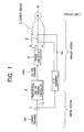
- Fig. 1 shows a conventional method of this type which has generally been used as a method for driving a servo-motor.
- a current command Icmd is input to a calculator 1.
- the output la of the calculator 1 is sent via a proportional and/or integral controller 2 and is input as a voltage command 2a to a power converter 3, comprising a known power element configuration.
- the power converter 3 supplies a three-phase drive current Iu, Iv, Iw to a servo-motor 4.
- a current sensor 5 detects one part of the three-phase drive current Iu, Iv, Iw, and the detected current value Ivcc is input to the calculator 1 via an A/D converter 6, thereby forming a current feedback control.
- the present invention has been realized in order to solve the above problems and particularly aims to provide a method for driving a servo-motor wherein, by detecting power voltage without using a conventional current feedback loop for motor current detection and controlling current using this detected value, control properties can be improved and cost lowered.
- the method for driving a servo-motor based on a current command of the present invention comprises the steps of: detecting a power voltage for driving the servo-motor; current-controlling a drive current of the servo-motor using a detected value of the power voltage; correcting a motor resistance, used in a numeric calculation of the current-controlling, using an estimated value of increase in motor resistance obtained using a command voltage, based on the current command, and an output power, which is the product of the power voltage and power current; and correcting changes in motor resistance caused by an increase in temperature of the servo-motor.
- the method of the present invention may comprise performing a numeric calculation using motor resistance, motor inductance, an induced voltage constant and a torque constant.
- the method of the present invention may comprise performing the current-controlling using a reverse calculation system Ra + Las, which is reverse with respect to the calculation system of the servo-motor (where Ra is motor resistance, La is motor inductance and s is a Laplace operator).
- the present invention also comprises apparatus for driving a servo-motor as set out in accompanying Claim 5.
- current command Icmd which comprises a current command value
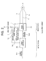
- a current controller 2A As shown in Fig. 2, current command Icmd, which comprises a current command value, is input to a current controller 2A and a voltage command Vcmd from the current controller 2A is applied to a known power converter 3.
- the power converter 3 supplies a three-phase drive current Iu, Iv, Iw to a servo-motor 4.
- a detected value Vcc of a power voltage V of the drive power source 6 and a detected value Ivcc of a power current I of the drive power source 6 are captured by the current controller 2A.
- the control system shown in Fig. 2 differs from the conventional control system of Fig. 1 in respect of the fact that the current controller 2A applies a voltage command 2a, which is controlled using the detected value Vcc of the power voltage V and the detected value Ivcc of the power current I of the drive source 6, to the power converter 3. Then, the servo-motor 4 is drive-controlled by the three-phase drive current Iu, Iv, Iw obtained from the power converter 3.
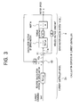
- Fig. 3 shows the calculation contents of the servo-motor 4 and the current controller 2A as blocks.
- the current command Icmd is input to a first calculator 10 via a reverse calculation system (Ra + Las) which is reverse with respect to the calculation system (1/Ra + Las) of the servo-motor 4.
- the output 10a from the first calculator 10 is input to a second calculator 11.
- the output lla of the second calculator 11 passes via the calculation system (1/Ra + Las), a torque constant kt and an inertia 1/Js, whereby a motor speed ⁇ is obtained.
- Ra represents motor resistance
- La represents motor inductance
- s represents a Laplace operator.
- Each induced voltage constant KE obtained from the motor speed ⁇ is input to the calculators 10 and 11.
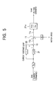
- control is carried out by means of a numeric calculation using a calculation control system comprising the calculation control blocks shown in Fig. 5.
- the current command Icmd is input to the second calculator 10 from the first calculator 10A via a first loop 20, wherein the response of the current response loop from the motor resistance R is 1, and a second-loop 21 ( ⁇ es, a product of the electrical time-constant ⁇ e and the Laplace operator s, where ⁇ e is equal to La [motor inductance] / Ra [motor resistance]) in the same way as already depicted in Fig. 3.
- a voltage calculator 21A controls the output 11a of the second calculator 11 by numeric calculation of Vcom/Vcc (where Vcom is a projected value of the power voltage V and Vcc is the detected value of the power voltage V). Then, the voltage command Vcmd, which has now been corrected in accordance with the fluctuation in the power voltage V, is applied to the power converter 3.
- K•Icmd ⁇ kt ⁇ ⁇ Vcc ⁇ Ivcc (where k is a proportional constant, Icmd is a motor current command, kt is the torque constant, ⁇ is the motor speed, Vcc is the detected value of power voltage and Ivcc is the detected value of power current). Therefore, a case where the above equality is not achieved is determined to be a state of motor overcurrent, namely a control irregularity.
- the servo-motor driving method of the present invention has the configuration described above and therefore obtains the following advantageous effects. That is, since the entire system can be controlled with a numeric calculation open loop, there is no need for the current feedback system using a current sensor and an A/D converter which has conventionally been used. The consequent reduction of parts enables cost to be reduced. In addition, deterioration of control precision caused by current sensor noise can be prevented. Furthermore, since changes in resistance due to increased temperature of the servo-motor are corrected, servo-motor rotation properties which are not dependent on temperature can be obtained, improving control performance.
Landscapes
- Engineering & Computer Science (AREA)
- Power Engineering (AREA)
- Control Of Electric Motors In General (AREA)
- Control Of Ac Motors In General (AREA)
Applications Claiming Priority (3)
| Application Number | Priority Date | Filing Date | Title |
|---|---|---|---|
| JP275901/97 | 1997-10-08 | ||
| JP27590197A JP3652083B2 (ja) | 1997-10-08 | 1997-10-08 | サーボモータ駆動方法 |
| JP27590197 | 1997-10-08 |
Publications (3)
| Publication Number | Publication Date |
|---|---|
| EP0909016A2 true EP0909016A2 (fr) | 1999-04-14 |
| EP0909016A3 EP0909016A3 (fr) | 1999-09-01 |
| EP0909016B1 EP0909016B1 (fr) | 2004-04-14 |
Family
ID=17562023
Family Applications (1)
| Application Number | Title | Priority Date | Filing Date |
|---|---|---|---|
| EP98307776A Expired - Lifetime EP0909016B1 (fr) | 1997-10-08 | 1998-09-24 | Procédé de commande d'un servomoteur |
Country Status (5)
| Country | Link |
|---|---|
| US (1) | US6025684A (fr) |
| EP (1) | EP0909016B1 (fr) |
| JP (1) | JP3652083B2 (fr) |
| DE (1) | DE69823136T2 (fr) |
| ES (1) | ES2219848T3 (fr) |
Cited By (1)
| Publication number | Priority date | Publication date | Assignee | Title |
|---|---|---|---|---|
| GB2391076B (en) * | 2002-05-28 | 2005-10-12 | Toshiba Machine Co Ltd | Servo control device |
Families Citing this family (2)
| Publication number | Priority date | Publication date | Assignee | Title |
|---|---|---|---|---|
| KR100459694B1 (ko) * | 1998-04-08 | 2005-04-06 | 삼성전자주식회사 | 모터 토크 상수 측정방법 |
| CN102497161B (zh) * | 2011-11-08 | 2014-02-19 | 浙江双友物流器械股份有限公司 | 大电流设备的驱动装置、控制装置及控制方法 |
Family Cites Families (4)
| Publication number | Priority date | Publication date | Assignee | Title |
|---|---|---|---|---|
| JP2873689B2 (ja) * | 1988-01-29 | 1999-03-24 | ファナック株式会社 | 速度制御装置 |
| JPH06165567A (ja) * | 1992-11-17 | 1994-06-10 | Hitachi Ltd | 半導体集積回路装置 |
| KR950004717A (ko) * | 1993-07-15 | 1995-02-18 | 가나이 쯔또무 | 브러시리스 모터구동회로 |
| JP3419157B2 (ja) * | 1995-07-20 | 2003-06-23 | 株式会社日立製作所 | モータ駆動方法及びそれを用いた電気機器 |
-
1997
- 1997-10-08 JP JP27590197A patent/JP3652083B2/ja not_active Expired - Fee Related
-
1998
- 1998-09-17 US US09/154,856 patent/US6025684A/en not_active Expired - Fee Related
- 1998-09-24 ES ES98307776T patent/ES2219848T3/es not_active Expired - Lifetime
- 1998-09-24 DE DE69823136T patent/DE69823136T2/de not_active Expired - Fee Related
- 1998-09-24 EP EP98307776A patent/EP0909016B1/fr not_active Expired - Lifetime
Cited By (3)
| Publication number | Priority date | Publication date | Assignee | Title |
|---|---|---|---|---|
| GB2391076B (en) * | 2002-05-28 | 2005-10-12 | Toshiba Machine Co Ltd | Servo control device |
| US7002315B2 (en) | 2002-05-28 | 2006-02-21 | Toshiba Kikai Kabushiki Kaisha | Servo control device |
| US7541763B2 (en) | 2002-05-28 | 2009-06-02 | Toshiba Kikai Kabushiki Kaisha | Servo control device |
Also Published As
| Publication number | Publication date |
|---|---|
| US6025684A (en) | 2000-02-15 |
| JPH11122962A (ja) | 1999-04-30 |
| EP0909016B1 (fr) | 2004-04-14 |
| JP3652083B2 (ja) | 2005-05-25 |
| DE69823136D1 (de) | 2004-05-19 |
| ES2219848T3 (es) | 2004-12-01 |
| DE69823136T2 (de) | 2004-08-19 |
| EP0909016A3 (fr) | 1999-09-01 |
Similar Documents
| Publication | Publication Date | Title |
|---|---|---|
| JP2833463B2 (ja) | 交流モータの回転トルク検出装置 | |
| JPH0683403A (ja) | 適応pi制御方式 | |
| JP5124899B2 (ja) | モータ制御方法およびその装置 | |
| WO1989003611A1 (fr) | Procede de commande d'un servomoteur | |
| EP0909016A2 (fr) | Procédé de commande d'un servomoteur | |
| US6011370A (en) | Servo-motor driving method | |
| US6020707A (en) | Servo-motor driving method | |
| JP3354633B2 (ja) | ステッピングモータ駆動装置 | |
| JP2749500B2 (ja) | サーボモータのウォムアップドリフト補償装置及び方法 | |
| JPH01170386A (ja) | モータの制御装置 | |
| JPH05137367A (ja) | モータ制御装置 | |
| JP3438195B2 (ja) | モータの制御装置 | |
| JPH11208490A (ja) | 電動パワーステアリングの制御装置 | |
| JPH11150977A (ja) | 直列接続電動機の速度制御装置 | |
| JP3811926B2 (ja) | 電動機の速度制御装置 | |
| JP3252427B2 (ja) | サーボモータの制御装置 | |
| JP3291902B2 (ja) | サーボ制御装置 | |
| SU1037400A1 (ru) | След щий электропривод | |
| KR840001389B1 (ko) | 직류 서보계의 속도 제어장치 | |
| JPS6132120A (ja) | 位置決め制御方式 | |
| JPH0887331A (ja) | 位置フィードバック補正方法 | |
| JP3810461B2 (ja) | サーボアンプの並列運転方法 | |
| JPH10127076A (ja) | 電動機の状態帰還制御方法および装置 | |
| KR0162434B1 (ko) | 스위치드 리럭턴스 모터의 속도제어 장치 | |
| JP2001178170A (ja) | 電流制御回路及び方法 |
Legal Events
| Date | Code | Title | Description |
|---|---|---|---|
| PUAI | Public reference made under article 153(3) epc to a published international application that has entered the european phase |
Free format text: ORIGINAL CODE: 0009012 |
|
| AK | Designated contracting states |
Kind code of ref document: A2 Designated state(s): BE CH DE ES FR GB IT LI NL SE |
|
| AX | Request for extension of the european patent |
Free format text: AL;LT;LV;MK;RO;SI |
|
| PUAL | Search report despatched |
Free format text: ORIGINAL CODE: 0009013 |
|
| AK | Designated contracting states |
Kind code of ref document: A3 Designated state(s): AT BE CH CY DE DK ES FI FR GB GR IE IT LI LU MC NL PT SE |
|
| AX | Request for extension of the european patent |
Free format text: AL;LT;LV;MK;RO;SI |
|
| RIC1 | Information provided on ipc code assigned before grant |
Free format text: 6H 02P 5/00 A, 6H 02P 7/62 B |
|
| 17P | Request for examination filed |
Effective date: 19990909 |
|
| 17Q | First examination report despatched |
Effective date: 20000222 |
|
| AKX | Designation fees paid |
Free format text: BE CH DE ES FR GB IT LI NL SE |
|
| GRAP | Despatch of communication of intention to grant a patent |
Free format text: ORIGINAL CODE: EPIDOSNIGR1 |
|
| GRAS | Grant fee paid |
Free format text: ORIGINAL CODE: EPIDOSNIGR3 |
|
| GRAA | (expected) grant |
Free format text: ORIGINAL CODE: 0009210 |
|
| AK | Designated contracting states |
Kind code of ref document: B1 Designated state(s): BE CH DE ES FR GB IT LI NL SE |
|
| REG | Reference to a national code |
Ref country code: GB Ref legal event code: FG4D |
|
| REG | Reference to a national code |
Ref country code: CH Ref legal event code: NV Representative=s name: WILLIAM BLANC & CIE CONSEILS EN PROPRIETE INDUSTRI Ref country code: CH Ref legal event code: EP |
|
| REF | Corresponds to: |
Ref document number: 69823136 Country of ref document: DE Date of ref document: 20040519 Kind code of ref document: P |
|
| REG | Reference to a national code |
Ref country code: SE Ref legal event code: TRGR |
|
| PGFP | Annual fee paid to national office [announced via postgrant information from national office to epo] |
Ref country code: NL Payment date: 20040905 Year of fee payment: 7 |
|
| PGFP | Annual fee paid to national office [announced via postgrant information from national office to epo] |
Ref country code: SE Payment date: 20040906 Year of fee payment: 7 |
|
| PGFP | Annual fee paid to national office [announced via postgrant information from national office to epo] |
Ref country code: FR Payment date: 20040908 Year of fee payment: 7 |
|
| PGFP | Annual fee paid to national office [announced via postgrant information from national office to epo] |
Ref country code: DE Payment date: 20040916 Year of fee payment: 7 |
|
| PGFP | Annual fee paid to national office [announced via postgrant information from national office to epo] |
Ref country code: GB Payment date: 20040922 Year of fee payment: 7 |
|
| PGFP | Annual fee paid to national office [announced via postgrant information from national office to epo] |
Ref country code: CH Payment date: 20040929 Year of fee payment: 7 Ref country code: ES Payment date: 20040929 Year of fee payment: 7 |
|
| PGFP | Annual fee paid to national office [announced via postgrant information from national office to epo] |
Ref country code: BE Payment date: 20041122 Year of fee payment: 7 |
|
| REG | Reference to a national code |
Ref country code: ES Ref legal event code: FG2A Ref document number: 2219848 Country of ref document: ES Kind code of ref document: T3 |
|
| ET | Fr: translation filed | ||
| PLBE | No opposition filed within time limit |
Free format text: ORIGINAL CODE: 0009261 |
|
| STAA | Information on the status of an ep patent application or granted ep patent |
Free format text: STATUS: NO OPPOSITION FILED WITHIN TIME LIMIT |
|
| 26N | No opposition filed |
Effective date: 20050117 |
|
| PG25 | Lapsed in a contracting state [announced via postgrant information from national office to epo] |
Ref country code: IT Free format text: LAPSE BECAUSE OF NON-PAYMENT OF DUE FEES Effective date: 20050924 Ref country code: GB Free format text: LAPSE BECAUSE OF NON-PAYMENT OF DUE FEES Effective date: 20050924 |
|
| PG25 | Lapsed in a contracting state [announced via postgrant information from national office to epo] |
Ref country code: SE Free format text: LAPSE BECAUSE OF NON-PAYMENT OF DUE FEES Effective date: 20050925 |
|
| PG25 | Lapsed in a contracting state [announced via postgrant information from national office to epo] |
Ref country code: ES Free format text: LAPSE BECAUSE OF NON-PAYMENT OF DUE FEES Effective date: 20050926 |
|
| PG25 | Lapsed in a contracting state [announced via postgrant information from national office to epo] |
Ref country code: LI Free format text: LAPSE BECAUSE OF NON-PAYMENT OF DUE FEES Effective date: 20050930 Ref country code: CH Free format text: LAPSE BECAUSE OF NON-PAYMENT OF DUE FEES Effective date: 20050930 Ref country code: BE Free format text: LAPSE BECAUSE OF NON-PAYMENT OF DUE FEES Effective date: 20050930 |
|
| PG25 | Lapsed in a contracting state [announced via postgrant information from national office to epo] |
Ref country code: NL Free format text: LAPSE BECAUSE OF NON-PAYMENT OF DUE FEES Effective date: 20060401 Ref country code: DE Free format text: LAPSE BECAUSE OF NON-PAYMENT OF DUE FEES Effective date: 20060401 |
|
| REG | Reference to a national code |
Ref country code: CH Ref legal event code: PL |
|
| EUG | Se: european patent has lapsed | ||
| GBPC | Gb: european patent ceased through non-payment of renewal fee |
Effective date: 20050924 |
|
| PG25 | Lapsed in a contracting state [announced via postgrant information from national office to epo] |
Ref country code: FR Free format text: LAPSE BECAUSE OF NON-PAYMENT OF DUE FEES Effective date: 20060531 |
|
| NLV4 | Nl: lapsed or anulled due to non-payment of the annual fee |
Effective date: 20060401 |
|
| REG | Reference to a national code |
Ref country code: FR Ref legal event code: ST Effective date: 20060531 |
|
| REG | Reference to a national code |
Ref country code: ES Ref legal event code: FD2A Effective date: 20050926 |
|
| BERE | Be: lapsed |
Owner name: *TAMAGAWA SEIKI K.K. Effective date: 20050930 |