EP0909583A1 - Catalyseurs sur support, procédé pour la préparation, ainsi que son utilisation - Google Patents
Catalyseurs sur support, procédé pour la préparation, ainsi que son utilisation Download PDFInfo
- Publication number
- EP0909583A1 EP0909583A1 EP98306104A EP98306104A EP0909583A1 EP 0909583 A1 EP0909583 A1 EP 0909583A1 EP 98306104 A EP98306104 A EP 98306104A EP 98306104 A EP98306104 A EP 98306104A EP 0909583 A1 EP0909583 A1 EP 0909583A1
- Authority
- EP
- European Patent Office
- Prior art keywords
- catalyst
- carrier
- supported
- aluminum
- supported catalyst
- Prior art date
- Legal status (The legal status is an assumption and is not a legal conclusion. Google has not performed a legal analysis and makes no representation as to the accuracy of the status listed.)
- Granted
Links
Images


Classifications
-
- B—PERFORMING OPERATIONS; TRANSPORTING
- B01—PHYSICAL OR CHEMICAL PROCESSES OR APPARATUS IN GENERAL
- B01J—CHEMICAL OR PHYSICAL PROCESSES, e.g. CATALYSIS OR COLLOID CHEMISTRY; THEIR RELEVANT APPARATUS
- B01J37/00—Processes, in general, for preparing catalysts; Processes, in general, for activation of catalysts
- B01J37/02—Impregnation, coating or precipitation
- B01J37/0215—Coating
-
- B—PERFORMING OPERATIONS; TRANSPORTING
- B01—PHYSICAL OR CHEMICAL PROCESSES OR APPARATUS IN GENERAL
- B01J—CHEMICAL OR PHYSICAL PROCESSES, e.g. CATALYSIS OR COLLOID CHEMISTRY; THEIR RELEVANT APPARATUS
- B01J35/00—Catalysts, in general, characterised by their form or physical properties
- B01J35/50—Catalysts, in general, characterised by their form or physical properties characterised by their shape or configuration
- B01J35/56—Foraminous structures having flow-through passages or channels, e.g. grids or three-dimensional [3D] monoliths
- B01J35/57—Honeycombs
-
- B—PERFORMING OPERATIONS; TRANSPORTING
- B01—PHYSICAL OR CHEMICAL PROCESSES OR APPARATUS IN GENERAL
- B01J—CHEMICAL OR PHYSICAL PROCESSES, e.g. CATALYSIS OR COLLOID CHEMISTRY; THEIR RELEVANT APPARATUS
- B01J37/00—Processes, in general, for preparing catalysts; Processes, in general, for activation of catalysts
- B01J37/02—Impregnation, coating or precipitation
- B01J37/0215—Coating
- B01J37/0225—Coating of metal substrates
-
- B—PERFORMING OPERATIONS; TRANSPORTING
- B01—PHYSICAL OR CHEMICAL PROCESSES OR APPARATUS IN GENERAL
- B01J—CHEMICAL OR PHYSICAL PROCESSES, e.g. CATALYSIS OR COLLOID CHEMISTRY; THEIR RELEVANT APPARATUS
- B01J37/00—Processes, in general, for preparing catalysts; Processes, in general, for activation of catalysts
- B01J37/06—Washing
-
- F—MECHANICAL ENGINEERING; LIGHTING; HEATING; WEAPONS; BLASTING
- F25—REFRIGERATION OR COOLING; COMBINED HEATING AND REFRIGERATION SYSTEMS; HEAT PUMP SYSTEMS; MANUFACTURE OR STORAGE OF ICE; LIQUEFACTION SOLIDIFICATION OF GASES
- F25D—REFRIGERATORS; COLD ROOMS; ICE-BOXES; COOLING OR FREEZING APPARATUS NOT OTHERWISE PROVIDED FOR
- F25D17/00—Arrangements for circulating cooling fluids; Arrangements for circulating gas, e.g. air, within refrigerated spaces
- F25D17/04—Arrangements for circulating cooling fluids; Arrangements for circulating gas, e.g. air, within refrigerated spaces for circulating air, e.g. by convection
- F25D17/042—Air treating means within refrigerated spaces
-
- F—MECHANICAL ENGINEERING; LIGHTING; HEATING; WEAPONS; BLASTING
- F25—REFRIGERATION OR COOLING; COMBINED HEATING AND REFRIGERATION SYSTEMS; HEAT PUMP SYSTEMS; MANUFACTURE OR STORAGE OF ICE; LIQUEFACTION SOLIDIFICATION OF GASES
- F25D—REFRIGERATORS; COLD ROOMS; ICE-BOXES; COOLING OR FREEZING APPARATUS NOT OTHERWISE PROVIDED FOR
- F25D17/00—Arrangements for circulating cooling fluids; Arrangements for circulating gas, e.g. air, within refrigerated spaces
- F25D17/04—Arrangements for circulating cooling fluids; Arrangements for circulating gas, e.g. air, within refrigerated spaces for circulating air, e.g. by convection
-
- F—MECHANICAL ENGINEERING; LIGHTING; HEATING; WEAPONS; BLASTING
- F25—REFRIGERATION OR COOLING; COMBINED HEATING AND REFRIGERATION SYSTEMS; HEAT PUMP SYSTEMS; MANUFACTURE OR STORAGE OF ICE; LIQUEFACTION SOLIDIFICATION OF GASES
- F25D—REFRIGERATORS; COLD ROOMS; ICE-BOXES; COOLING OR FREEZING APPARATUS NOT OTHERWISE PROVIDED FOR
- F25D2317/00—Details or arrangements for circulating cooling fluids; Details or arrangements for circulating gas, e.g. air, within refrigerated spaces, not provided for in other groups of this subclass
- F25D2317/04—Treating air flowing to refrigeration compartments
- F25D2317/041—Treating air flowing to refrigeration compartments by purification
- F25D2317/0416—Treating air flowing to refrigeration compartments by purification using an ozone generator
Definitions
- This invention relates to a supported catalyst having a catalytic material supported on a carrier which is substantially nonadsorptive of specific components in malodor, deleterious or other objectionable gases that are to be removed or decomposed, thereby preventing the emission of unpleasant odors and other undesirable phenomena due to said particular components.
- the invention also relates to an improved aluminum-supported catalyst with upgraded adhesion between the carrier and a catalyst layer of the catalytic material supported thereon.
- the invention further relates to processes for producing such supported catalysts, as well as a direct-cool refrigerator assembled therein.
- odor components that are composed of eg. oxides of sulphur (SOx), nitrogen compounds such as oxides of nitrogen (NOx) ammonia and amines, alochols, aldehydes, organic acids such as acetic acid and sulfur compounds such as hydrogen sulfide, mercaptan, dimethyl sulfide and dimethyl disulfide in atmospheric air, there have so far been developed many techniques and methods that rely upon the use of adsorbents, e.g. porous ceramics such as activated alumina and silica gel, zeolites, activated carbon and the like.
- Conventional deodorizing filters have been prepared by having deodorizing catalysts supported on porous ceramic or zeolite carriers capable of adsorbing odor components.
- the capability of such filters is not limited to decomposition of the odor components in the objectionable gases of interest by means of the deodorizing catalyst; due to the large pore volumes in the carrier, the odor components and the reaction products resulting from the catalytic deodorization can be effectively adsorbed thereon or stored therein to thereby abate the odor components.
- the odor components and the reaction products that have been adsorbed thereon or stored therein are so sensitive to changes in environmental factors such as temperature and humidity that they are liable to desorb from the deodorizing filter to thereby give off an unpleasant smell.
- Aluminum honeycomb structures have good weathering properties and high durability, and their walls can be made very thin; hence, the pressure drop that will develop in the structures is sufficiently reduced to make them suitable for use as catalyst supports in high-volume processing operations.
- An object, therefore, of the present invention is to provide a novel supported catalyst.
- the present invention relates to a supported catalyst characterized by having a catalytic material supported on a carrier that substantially lacks the ability to adsorb components to be removed or decomposed.
- the present invention relates to an aluminum-supported catalyst characterized in that an aluminum component dissolving out from an aluminum carrier has been incorporated and precipitated in the catalyst layer supported thereon so as that the aluminum carrier has become integral with the catalyst layer unitarily.
- the present invention relates to a process for producing the stated aluminum-supported catalyst by immersing an aluminum carrier supporting a catalyst layer thereon in a weak alkaline aqueous solution.
- the present invention relates to a direct-cool refrigerator assembled with said supported catalyst.
- the support or carrier material for the supported catalyst according to the first aspect of the invention is not limited to any particular type insofar as it is substantially deficient of the ability to adsorb specific odor components to be removed or decomposed.
- Preferred examples include nonadsorptive ceramics such as ⁇ -alumina, cordierite and mullite, metals, particularly stainless steel which is resistant to corrosion, as well as elementary aluminum and aluminum layer-covered metals that are lightweight and easy to handle.
- the carrier of the catalyst of the invention can be shaped to various forms including a honeycomb, a corrugation, a plate, a foil, a screen and a wool; these forms are preferred since their combinations can be processed to geometrical shapes that fit diverse purposes.
- the carrier is preferably shaped into a honeycomb structure and a particularly preferred support is a honeycomb structure made of an aluminum foil.
- This type of carrier can be prepared by a known method for producing a laminate for a honeycomb structure as described in Japanese Patent Public Disclosure No. 338065/1993.
- the use of metal foils is very advantageous for the purpose of reducing the pressure loss and they can be processed and produced at an incomparably low cost.
- the thickness of metal foils can be selected at any values from the range of 10 - 200 ⁇ m. A particularly preferred range is 10 - 50 ⁇ m, with the range of 10 - 30 ⁇ m being the most preferred.
- the catalytic material to be used in the supported catalyst according to the first aspect of the invention is not limited to any particular type insofar as it is capable of decomposing or removing a specific component such as odor components that is to be decomposed or removed.
- platinum group elements such as platinum, palladium, osmium, iridium and rhodium, iron group elements such as iron, cobalt and nickel, elements of group I such as copper and silver, elements of group VII such as manganese and rare earth metals such as cerium and lanthanum may be used as catalytic materials either independently or in appropriate combinations in either an elementary, oxide or complex form.
- Hopcalite which is a complex of manganese and copper can be used as a preferred deodorizing catalytic material.
- the catalytic material is generally supported on the carrier in an amount of 0.1 - 50 grams per liter, preferably 0.5 - 30 grams per liter.
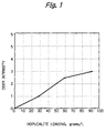
- the supported catalyst is to be used as a deodorizer, if the catalytic material is supported in an amount of less than 0.1 gram per liter, it may fail to exhibit the desired deodorizing performance. If more than 50 grams per liter of the catalytic material is supported, the supported catalytic material will adsorb by itself the odor components that has to be removed or decomposed and the deodorizing filter will give off an unpleasant odors.
- the catalytic material can be supported by any conventional method such as the slurry method using inorganic binders such as silica and alumina sols or organic binders such as natural resins (e.g. starch, casein or gelatin) and various water-soluble synthetic resins including cellulose, water-soluble polyamides and quaternary ammonium salts.
- a particularly preferred binder is a water-base acrylic urethane resin coating because it gives a glossy and thick film and exhibits high hardness, high chemical resistance, good deflection (flexing properties) and high wear resistance.
- the weight ratio of the binder to the catalytic material is generally 1:5 to 1:20, preferably 1:6 to 1:12; if an organic binder is to be used, the weight ratio of the binder to the catalytic material is 1:5 to 1:40, preferably 1:7 to 1:20. If the binder, whether inorganic or organic, is used in an unduly small amount, the necessary strength of support is not attained and the catalytic material will readily separate from the support, a defect generally called "flaking" or "shedding". If the binder is used in an excessively large amount, the catalytic material is covered by the binder and fails to exhibit the intended catalytic activity.
- a catalyst layer of the catalytic material may be supported on an aluminum carrier.
- the aluminum-supported catalyst is manufactured by leaching an aluminum component from the aluminum carrier such that leached aluminum component is incorporated and precipitated into the catalyst layer so as to form a unitary body integral with the aluminum carrier and the catalyst layer as described hereinafter.
- a catalyst layer of the catalytic material is supported on an aluminum carrier; after drying, the dried aluminum-supported catalyst is immersed in a weak alkaline aqueous solution; if the pH of the alkaline aqueous solution is adjusted between 7 and 10, preferably between 8.5 and 9.5, aluminum on the surface of the aluminum carrier will react with the alkali in the aqueous solution very slowly, thereby causing an aluminum component such as aluminum hydroxide to leach out.
- the leached aluminum component is incorporated into the catalyst layer supported thereon and precipitated in its interstices to become integral with it; in this way, the catalyst layer is firmly fixed and secured to the aluminum carrier, thereby achieving a marked improvement in the strength of support of the catalyst layer thereon.
- the aluminum carrier will give hydrogen gas from the surface of the carrier as it reacts with the alkali so violently that the catalyst layer will separate from the carrier.
- Hopcalite which is a complex oxide of copper and manganese is an effective catalytic component for deodorizing or ozone decomposition. Since hopcalite contains 1 - 4% of potassium, the aluminum carrier supporting it needs only to be dipped in water so that the contained potassium will dissolve out therefrom to provide the desired pH.
- the dipping time depends largely upon the pH of the alkaline aqueous solution and the required volume of treatment with the supported catalyst; it ranges generally from 5 to 48 hours, preferably from 5 to 24 hours. If the dipping time is unduly prolonged, the surface of the catalyst layer will be covered with the precipitated aluminum hydroxide; this is effective for increasing the strength of support but, on the other hand, the catalytic activity may occasionally be reduced.
- the supported catalyst having a catalytic material supported on a carrier that substantially lacks the ability to adsorb components to be removed or decomposed may be installed in a refrigerator, particularly a direct-cool one, in positions near the chilling section thereof.
- a refrigerator particularly a direct-cool one
- the temperature in the refrigerating compartment will change cyclically and natural convection will occur accordingly in the internal air to accomplish effective removal of the odor components from the refrigerating compartment.
- the supported catalyst according to the first aspect of the invention which is less likely to give off unpleasant odor components in the face of environmental changes such as temperature changes or even in a humid condition.
- Ion-exchanged water (1824 g) was mixed with 220 g of a water-based urethane resin coating (water-based urethane MOKUBU CLEAR, the trade name of Washin Kagaku Kogyo K.K.). Thereafter 100 g of hopcalite (N-840, the trade name of Nissan Girdler Catalyst Co. Ltd. containing 20.5 wt.% CuO, 54.4 wt.% MnO and 2.6 wt.% K) was added and the mixture was stirred to prepare a slurry solution.
- hopcalite N-840, the trade name of Nissan Girdler Catalyst Co. Ltd. containing 20.5 wt.% CuO, 54.4 wt.% MnO and 2.6 wt.% K
- the slurry solution was then sprayed over an aluminum foil honeycomb support (product of Oji Kenzai Kogyo K.K.; 350 cells/in 2 ; 35.5 mm x 69 mm x 10 mm), which had been fabricated by expanding a laminate of 15 ⁇ m thick aluminum foils.
- the excess slurry solution was blown off by a jet of air and the assembly was dried at a temperature of 150°C for 1 hour to prepare aluminum foil honeycomb-supported catalyst A having 26.4 g of hopcalite and 2.6 g of urethane resin supported per liter of the catalyst.
- Ion-exchanged water (778 g) was mixed with an alumina sol (ALUMINA SOL, the trade name of Nissan Chemical Industries, Ltd.). Thereafter, 1000 g of hopcalite (N-840, the trade name of Nissan Girdler Catalyst Co., Ltd.; containing 20.5 wt.% CuO, 54.4 wt.% Mno and 2.6 wt.% K) was added and the mixture was stirred to prepare a slurry solution. The slurry solution was sprayed over an aluminum foil honeycomb support (product of Oji Kenzai Kogyo K.K.; 350 cells/in 2 ; 35.5 mm x 69 mm x 10 mm), which had been fabricated as described in Example 1.
- Example 2 The same slurry solution as prepared in Example 2 was sprayed over a cordierite honeycomb support (product of NGK INSULATORS, LTD.; 400 cells/in 2 ; 35.5 mm x 69 mm x 10 mm) and the excess slurry solution was blown off with a jet of air. Thereafter, the assembly was dried at a temperature of 150°C for 1 hour to prepare cordierite honeycomb-supported catalyst C having 28.5 g of hopcalite and 2.8 g alumina supported per liter of the catalyst.
- a cordierite honeycomb support product of NGK INSULATORS, LTD.; 400 cells/in 2 ; 35.5 mm x 69 mm x 10 mm
- Ion-exchanged water (614 g) was mixed with an alumina sol (ALUMINA SOL 200, the trade name of Nissan Chemical Industries, Ltd.). Thereafter, 700 g of hopcalite (N-840, the trade name of Nissan Girdler Catalyst Co., Ltd.; containing 20.5 wt.% CuO, 54.4 wt.% MnO and 2.6 wt.% K) and 249 g of a pentacil-type zeolite (PURASHIVE-420, the trade name of UOP; silica-to-alumina ratio ⁇ 400) were added and the mixture was stirred to prepare a slurry solution.
- hopcalite N-840, the trade name of Nissan Girdler Catalyst Co., Ltd.; containing 20.5 wt.% CuO, 54.4 wt.% MnO and 2.6 wt.% K
- PURASHIVE-420 the trade name of UOP; silica-to-alumina ratio ⁇ 400
- the excess slurry solution was blown off with a jet of air and, thereafter, the assembly was dried at a temperature of 150°C for 1 hour to prepare HONEYCLE-supported catalyst X having 2.49 g of hopcalite, 10.7 g of zeolite and 4.0 g of alumina supported per liter of the catalyst.
- the conventional porous HONEYCLE carrier and the catalyst having a deodorizing catalytic material supported on that porous HONEYCLE carrier both of which had been exposed to various malodors in the refrigerator, gave off unpleasant odors in a high humid condition.
- the aluminum foil honeycomb carrier used in Examples 1 and 2 the catalysts A and B having a deodorizing catalytic material supported on that carrier, as well as the cordierite honeycomb carrier used in Example 3 and the catalyst C having the same deodorizing catalytic material supported on that honeycomb carrier were less likely to give off unpleasant odors in the face of a temperature change in a high humid condition.
- Samples of supported catalyst each cut to a size of 35.5 mm x 69 mm x 10 mm were installed in a 16-L closed glass container adjusted to a temperature of 5°C and a humidity of 50%.
- the glass container was injected with specified amounts of three odor components, i.e. ethyl acetate, ethyl alcohol and toluene.
- the adsorption isotherms of the three catalyst samples were measured for each odor component and the saturated adsorption (mg) of one unit of each catalyst sample was determined for each odor component at an equilibrium concentration of 100 ppm.
- Table 2 The results are shown in Table 2 below.
- Example 1 Carrier or Supported Catalyst Ethyl Alcohol (ppm) Aluminum foil honeycomb-supported Catalyst A of Example 1 22 Aluminum foil honeycomb-supported Catalyst B of Example 2 28 Cordierite honeycomb-supported Catalyst C of Example 3 35 Aluminum foil honeycomb carrier used in Examples 1 and 2 ⁇ 1 Cordierite honeycomb carrier used in Examples 3 3 HONEYCLE-supported Catalyst X of Comparative Example 1 215 HONEYCLE carrier used in Comparative Example 1 150
- the aluminum foil honeycomb carrier and the cordierite honeycomb carrier that were specified by the invention as carriers substantially nonadsorptive of odor components, as well as the Catalysts A and B of Examples 1 and 2, respectively, which had a deodorizing catalytic material supported on the aluminum foil honeycomb carrier and the Catalyst C having the same deodorizing catalytic material supported on the cordierite honeycomb carrier emitted ethyl alcohol in amounts no more than a seventh of the concentrations emitted from the comparative porous samples.
- This provides a proof of the fact that the supported catalysts of the invention which have a deodorizing catalytic material supported on carriers substantially nonadsorptive of odor components are less likely to give off unpleasant odors in the face of environmental changes.
- Samples of supported catalyst each cut to a cylindrical shape of 21 mm in diameter and 10 mm in thickness were installed in a flow-type reactor, through which a sample gas containing 100 ppm of methylmercaptan and having ambient temperature and humidity was passed at a flow rate of 90,000 liters per hour. Thirty minutes after starting the passage of the sample gas, the concentration of methyl mercaptan was measured at both the entrance and exit of the reactor by means of an FPD gas chromatographic analyzer and the percent removal of methyl mercaptan after 30 min was calculated. The results are shown in Table 4 below.
- the Catalysts A and B of Examples 1 and 2 of the invention having a deodorizing catalytic material supported on the aluminum carrier which was substantially nonadsorptive of odor components, as well as the Catalyst C of Example 3 having the same deodorizing catalytic material supported on the cordierite honeycomb carrier which was also substantially nonadsorptive of odor components were no less effective in removing methyl mercaptan (a representative malodorous substance emitted from foods, in particular, proteins) than the Catalyst X of Comparative Example 1 which had a deodorizing catalytic material supported on the conventional porous carrier adsorptive of odor components.
- Example 2 Three samples of aluminum foil honeycomb-supported catalyst were prepared as in Example 1, except that the amount of hopcalite to be supported was varied by adjusting the spray frequency of the slurry solution. These samples were subjected to an olfactory test in accordance with the procedure described in Test 1. The results are shown in Figure 1, from which one can see that the emission of an unpleasant odor became perceivable when more than 50 g of hopcalite was supported per liter of the deodorizing filter.
- Ion-exchanged water (778 g) was mixed with 830 g of an alumina sol (ALUMINA SOL 200, the trade name of Nissan Chemical Industries, Ltd.). Thereafter, 1000 g of hopcalite (N-840, the trade name of Nissan Girdler Catalyst Co. Ltd.; containing 20.5 wt.% CuO, 54.4 wt.% MnO and 2.6 wt.% K) was added and the mixture was stirred to prepare a slurry solution.
- AUMINA SOL 200 the trade name of Nissan Chemical Industries, Ltd.
- the slurry solution was sprayed over a honeycomb carrier (product of Oji Kenzai Kogyo K.K.; 350 cells/in 2 ; 35.5 mm x 69 mm x 10 mm) which was fabricated by expanding a laminate of 15- ⁇ m thick aluminum foils.
- the excess slurry solution was blown off with a jet of air and the assembly was dried at a temperature of 150°C for 1 hour to prepare aluminum foil honeycomb-supported Catalyst Y having 27.3 g of hopcalite and 2.7 g of alumina supported per liter of the catalyst.
- a portion (300 mL) of the aluminum foil honeycomb-supported Catalyst Y prepared in Comparative Example 2 was immersed in 200 mL of water for 24 hours.
- the catalyst was recovered from the water and dried at a temperature of 150°C for 1 hour to prepare aluminum foil honeycomb-supported Catalyst D which was an improved version of the aluminum foil honeycomb-supported Catalyst Y.
- water had a pH of 9.27.
- the improved aluminum foil honeycomb-supported Catalyst D was found to be 1.05 g heavier than the Catalyst Y of Comparative Example 2 which was not treated by immersing in water. This was probably because part of the surface of the aluminum carrier reacted with the alkali in the water to become a water-soluble aluminum component such as aluminum hydroxide.
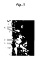
- the aluminum foil honeycomb-supported Catalyst Y of Comparative Example 2 and the Catalyst D of Example 5 which was improved according to the invention were examined for a cross section of their surface portion of the catalyst under an electron microscope at a magnification of 200 and the results are shown as photomicrographs in Figures 2 and 3, respectively.
- the electron microscope was a SEM of JEOL LTD. operated at an acceleration voltage of 20 kV.
- Figurer 2 obviously shows that the aluminum carrier 1 of the Catalyst Y supported the catalyst layer 2 containing a number of interstices 3.
- the surface of the aluminum carrier 1 in the improved Catalyst D was eroded by immersing in the weak alkaline aqueous solution, whereupon part of its surface changed to an aluminum component such as aluminum hydroxide which, in turn, dissolved out, causing a coarse surface 4 to form; the catalyst layer 2 had void 3, into which the aluminum component 5 such as aluminum hydroxide was incorporated and precipitated, thereby causing to form a unitary body integral with the catalyst layer 2 and the aluminum carrier 1.
- Analysis by X-ray diffraction verified that the precipitate in the voids 3 was an aluminum-containing component.
- the improved Catalyst D of Example 5 experienced a much smaller separation of the catalyst layer than the Catalyst Y of Comparative Example 2 which was not treated by immersing in water.
- This provides a support of the fact that the aluminum-supported catalyst of the invention which was characterized by integration of an aluminum component such as aluminum hydroxide from the aluminum carrier into the supported catalyst layer has a sufficient strength of support to secure resistance against separation of the supported catalyst layer.
- Aluminum foil honeycomb-supported Catalyst E having 0.73 g of hopcalite and 0.07 g of a urethane resin supported per catalyst on an aluminum foil honeycomb carrier was prepared as in Example 1, except that the honeycomb carrier had a different number of cells (500 cells/in 2 ).
- Aluminum foil honeycomb-supported Catalysts F, G and H having different amounts of hopcalite (0.65 g, 0.73 g and 0.78 g) and a urethane resin (0.06 g, 0.07 g and 0.08 g) supported per catalyst on aluminum foil honeycomb carriers were prepared as in Example 1, except that the carriers each measuring 71 mm x 69 mm x 10 mm had 350, 500 and 750 cells/in 2 .
- a 0.3-mm thick aluminum plate of a size of 71 mm x 69 mm was provided.
- a 0.05-mm thick aluminum foil was corrugated as shown in Figure 4.
- the aluminum plate was brush-coated with the same slurry solution as used in Example 1 and dried at a temperature of 150°C to prepare supported catalyst I having 0.15 g of hopcalite and 0.01 g of a urethane resin supported per catalyst on the aluminum plate.
- the aluminum corrugated foil was brush-coated with the same slurry as used in Example 1 and dried at a temperature of 150°C to prepare aluminum corrugated foil-supported Catalyst J having 0.25 g of hopcalite and 0.03 g of a urethane resin supported per catalyst on the corrugated aluminum foil.
- a stainless steel (SUS-304) plain wave screen of 20 mesh/in 2 (see Figure 5; wire diameter, 0.5 mm; screen opening, 0.77 mm) was dipped in the same slurry solution as used in Example 1. The screen was recovered and the excess slurry solution was blown off with a jet of air. The assembly was then dried at a temperature of 150°C to prepare stainless steel screen-supported Catalyst K having 0.16 g of hopcalite and 0.02 g of a urethane resin supported per catalyst on the stainless steel screen.
- a direct-cool refrigerator of the type shown in Figure 6 was used. It had a chilling section provided in the wall farthest from the front door and the interior of refrigerating compartment was cooled by the internal natural convection of air.
- a thermocouple was set in the following four positions to measure the temperatures in those positions: A on the farthest wall of the refrigerating compartment where the chilling section was provided; B on a side wall; C on the top wall; and D which was the center of the refrigerating compartment.
- the temperature in the refrigerating compartment was represented by the temperature in position D.
- the time profiles of the respective temperatures are shown graphically in Figure 7.
- the refrigerator under test was not equipped with a fan to forcibly agitate the internal air and the cooling of the interior of the refrigerator was solely cooled by natural convection under normal operating conditions.
- the temperature of the farthest wall (in position A) where the chilling section of the refrigerating compartment was provided varied cyclically between 5 and 25°C at intervals of 40 minutes.
- the temperatures in positions B (on a side wall), C (on the top wall) and D (at the center) were substantially constant.
- the farthest wall of the refrigerator where its chilling section was provided experienced the greatest change in temperature and one can reasonably assume that the strongest convection is taking place near the farthest wall of the refrigerator.
- Figure 8 shows graphically effect of the position of catalyst installation by plotting the time profiles of the methyl mercaptan level for the case where the aluminum foil honeycomb-supported catalyst F of Example 7 was set in position A (on the farthest wall of the refrigerating compartment), B (on a sidewall), C (on the top wall) and D (in the center).
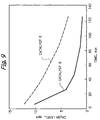
- Figure 9 shows how the efficiency of a deodorizing catalyst is affected by its cross-sectional area. The effect is shown graphically by the time profiles of the methyl mercaptan level for the case where the aluminum foil honeycomb-supported Catalyst E of Example 6 (35.5 mm x 69 mm x 10 mm) and the aluminum foil honeycomb-supported Catalyst G (71 mm x 69 mm x 5 mm) were set in position A on the farthest wall of the refrigerator. The two catalysts were the same in the number of cells and capacity but different in cross-sectional area.
- the Catalyst G having a larger cross-sectional area than the Catalyst E having the same capacity and cell number could achieve more efficient removal of methyl mercaptan. This provides a support of the fact that the efficiency of a deodorizing catalyst increases with the increasing area that traverses an air flow.
- Figure 10 shows how the efficiency of a deodorizing catalyst is affected by its geometry. The effect is shown graphically by the time profiles of the methyl mercaptan level for the case where the aluminum plate-supported Catalyst I, the corrugated aluminum foil-supported Catalyst J (both being fabricated in Example 8) and the stainless steel screen-supported Catalyst K of Example 9 were set in position A on the farthest wall of the refrigerator.
- the three catalysts were the same in cross-sectional area but different in geometry.
- Figure 11 shows how the efficiency of a deodorizing catalyst is affected by the number of cells it has. The effect is shown graphically by the time profiles of the methyl mercaptan level for the case where the aluminum foil honeycomb-supported Catalysts F, G and H of Example 6 which had 350, 500 and 750 cells, respectively, per square inch were set in position A on the farthest wall of the refrigerating compartment.
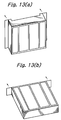
- Figure 12 shows how the efficiency of a deodorizing catalyst is affected by the method of its installation. The effect is shown graphically by the time profiles of the methyl mercaptan level for the following two cases: one where the aluminum foil honeycomb-supported Catalyst E of Example 6 (500 cells/in 2 ; 35.5 mm x 69 mm x 10 mm) was installed in a vertical direction along a plane 5 mm distant from the farthest wall of the refrigerating compartment (see Figure 13a); and the other where the same catalyst was installed in position A on the farthest wall of the refrigerating compartment in such a way that it protruded horizontally from the wall inside the refrigerating compartment (see Figure 13b).
- the aluminum foil honeycomb-supported Catalyst E of Example 6 500 cells/in 2 ; 35.5 mm x 69 mm x 10 mm
- the efficiency of the deodorizing catalyst could be improved by projecting it horizontally from the furthest wall of the refrigerating compartment so as to accomplish more efficient contact with the internal air.
- This provides a proof of the fact that the efficiency of a deodorizing catalyst can be improved by installing it in a position where it traverses the natural convection of air within the refrigerating compartment (i.e., it projects horizontally inside the refrigerating compartment as shown in Figure 13b).
- the present invention provides a novel deodorizing filter which, in the face of environmental changes, is less likely to give off unpleasant odors due to the malodor components that are adsorbed on or stored in the filter per se and which yet has comparable deodorizing performance to the existing deodorizing filters.
- an aluminum component such as aluminum hydroxide leaching out of the aluminum carrier is incorporated and precipitated into the interstices in the catalyst layer which hence form a unitary body integrated with the aluminum carrier and the catalyst layer.
- the strength of support of the catalyst layer against the aluminum carrier is accordingly enhanced to provide an improved aluminum-supported catalyst in which the catalyst layer supported thereon will not readily separate from the aluminum carrier.
- the efficiency of the deodorizing catalyst can be enhanced by fitting it in a direct-cool refrigerator in areas near the chilling section that serves as the driving force for creating natural convection of the air within the refrigerating compartment.
Landscapes
- Chemical & Material Sciences (AREA)
- Engineering & Computer Science (AREA)
- Materials Engineering (AREA)
- Organic Chemistry (AREA)
- Chemical Kinetics & Catalysis (AREA)
- Combustion & Propulsion (AREA)
- Physics & Mathematics (AREA)
- Mechanical Engineering (AREA)
- Thermal Sciences (AREA)
- General Engineering & Computer Science (AREA)
- Catalysts (AREA)
- Exhaust Gas Treatment By Means Of Catalyst (AREA)
- Disinfection, Sterilisation Or Deodorisation Of Air (AREA)
Priority Applications (1)
| Application Number | Priority Date | Filing Date | Title |
|---|---|---|---|
| EP01202035A EP1142635B1 (fr) | 1997-10-17 | 1998-07-30 | Catalyseurs supportés pour la désodorisation et méthode pour leur préparation |
Applications Claiming Priority (9)
| Application Number | Priority Date | Filing Date | Title |
|---|---|---|---|
| JP30369897 | 1997-10-17 | ||
| JP30369897 | 1997-10-17 | ||
| JP303698/97 | 1997-10-17 | ||
| JP30494197 | 1997-10-20 | ||
| JP304941/97 | 1997-10-20 | ||
| JP30494197 | 1997-10-20 | ||
| JP09625498A JP4263268B2 (ja) | 1997-10-17 | 1998-04-08 | アルミニウム製担体に触媒層を固定化する方法 |
| JP9625498 | 1998-04-08 | ||
| JP96254/98 | 1998-04-08 |
Related Child Applications (1)
| Application Number | Title | Priority Date | Filing Date |
|---|---|---|---|
| EP01202035A Division EP1142635B1 (fr) | 1997-10-17 | 1998-07-30 | Catalyseurs supportés pour la désodorisation et méthode pour leur préparation |
Publications (2)
| Publication Number | Publication Date |
|---|---|
| EP0909583A1 true EP0909583A1 (fr) | 1999-04-21 |
| EP0909583B1 EP0909583B1 (fr) | 2002-04-10 |
Family
ID=27308054
Family Applications (2)
| Application Number | Title | Priority Date | Filing Date |
|---|---|---|---|
| EP01202035A Expired - Lifetime EP1142635B1 (fr) | 1997-10-17 | 1998-07-30 | Catalyseurs supportés pour la désodorisation et méthode pour leur préparation |
| EP98306104A Expired - Lifetime EP0909583B1 (fr) | 1997-10-17 | 1998-07-30 | Réfrigérateur comprenant un matériel catalytique déodorisant et utilisation d'un catalyseur supporté dans un réfrigérateur. |
Family Applications Before (1)
| Application Number | Title | Priority Date | Filing Date |
|---|---|---|---|
| EP01202035A Expired - Lifetime EP1142635B1 (fr) | 1997-10-17 | 1998-07-30 | Catalyseurs supportés pour la désodorisation et méthode pour leur préparation |
Country Status (6)
| Country | Link |
|---|---|
| EP (2) | EP1142635B1 (fr) |
| JP (1) | JP4263268B2 (fr) |
| CN (1) | CN1112253C (fr) |
| DE (2) | DE69820310T2 (fr) |
| ES (2) | ES2211733T3 (fr) |
| HK (1) | HK1039583B (fr) |
Cited By (2)
| Publication number | Priority date | Publication date | Assignee | Title |
|---|---|---|---|---|
| WO2008030097A1 (fr) | 2006-09-08 | 2008-03-13 | Parker Filtration & Separation B.V. | Utilisation d'un moyen de conversion de l'ozone dans le traitement d'air d'un avion |
| CN114307634A (zh) * | 2022-01-05 | 2022-04-12 | 嘉兴沃特泰科环保科技股份有限公司 | 颗粒态脱硝剂及其制备方法和应用 |
Families Citing this family (7)
| Publication number | Priority date | Publication date | Assignee | Title |
|---|---|---|---|---|
| WO2000048734A1 (fr) * | 1999-02-18 | 2000-08-24 | Nikki-Universal Co., Ltd. | Catalyseur de desodorisation de l'air conditionne |
| MY156877A (en) * | 2007-09-21 | 2016-04-15 | Memc Electronic Materials | Processes for purification of silicon tetrafluoride |
| CN102166510A (zh) * | 2011-03-10 | 2011-08-31 | 胡冰 | 一种铂金抗菌除臭保鲜块 |
| CN107233607B (zh) * | 2017-06-27 | 2020-03-31 | 东莞御治医疗器械有限公司 | 一种创面保护膜材料的制备方法 |
| JP7081776B2 (ja) * | 2018-02-28 | 2022-06-07 | 住江織物株式会社 | オゾン、アセトアルデヒド、トルエン除去フィルター |
| JP7128391B2 (ja) * | 2018-11-05 | 2022-08-31 | 日揮ユニバーサル株式会社 | リフロー炉内ガスの浄化用触媒及びその製造方法、並びにリフロー炉内ガスの浄化方法 |
| KR20250010217A (ko) * | 2023-07-12 | 2025-01-21 | 희성촉매 주식회사 | 탈황용 망간계 흡착제 및 이의 제조방법 |
Citations (4)
| Publication number | Priority date | Publication date | Assignee | Title |
|---|---|---|---|---|
| GB804490A (en) * | 1956-08-27 | 1958-11-19 | Gen Motors Corp | Improvements in refrigerators |
| EP0398263A2 (fr) * | 1989-05-16 | 1990-11-22 | Canon Kabushiki Kaisha | Appareil électrophotographique |
| JPH0584441A (ja) * | 1991-09-26 | 1993-04-06 | Hitachi Ltd | 脱臭触媒及びそれを用いた応用機器 |
| JPH10267510A (ja) * | 1997-03-28 | 1998-10-09 | Matsushita Refrig Co Ltd | 冷却装置の脱臭装置 |
Family Cites Families (1)
| Publication number | Priority date | Publication date | Assignee | Title |
|---|---|---|---|---|
| CA2052395A1 (fr) * | 1990-09-29 | 1992-03-30 | Sadao Terui | Catalyseur et methode de preparation |
-
1998
- 1998-04-08 JP JP09625498A patent/JP4263268B2/ja not_active Expired - Fee Related
- 1998-04-29 CN CN98107769A patent/CN1112253C/zh not_active Expired - Lifetime
- 1998-07-30 EP EP01202035A patent/EP1142635B1/fr not_active Expired - Lifetime
- 1998-07-30 DE DE69820310T patent/DE69820310T2/de not_active Expired - Fee Related
- 1998-07-30 EP EP98306104A patent/EP0909583B1/fr not_active Expired - Lifetime
- 1998-07-30 DE DE69804740T patent/DE69804740T2/de not_active Expired - Lifetime
- 1998-07-30 ES ES01202035T patent/ES2211733T3/es not_active Expired - Lifetime
- 1998-07-30 ES ES98306104T patent/ES2175620T3/es not_active Expired - Lifetime
-
2002
- 2002-02-06 HK HK02100945.4A patent/HK1039583B/en not_active IP Right Cessation
Patent Citations (4)
| Publication number | Priority date | Publication date | Assignee | Title |
|---|---|---|---|---|
| GB804490A (en) * | 1956-08-27 | 1958-11-19 | Gen Motors Corp | Improvements in refrigerators |
| EP0398263A2 (fr) * | 1989-05-16 | 1990-11-22 | Canon Kabushiki Kaisha | Appareil électrophotographique |
| JPH0584441A (ja) * | 1991-09-26 | 1993-04-06 | Hitachi Ltd | 脱臭触媒及びそれを用いた応用機器 |
| JPH10267510A (ja) * | 1997-03-28 | 1998-10-09 | Matsushita Refrig Co Ltd | 冷却装置の脱臭装置 |
Non-Patent Citations (2)
| Title |
|---|
| DATABASE WPI Section Ch Week 9318, Derwent World Patents Index; Class D22, AN 93-148601, XP002089493 * |
| DATABASE WPI Section Ch Week 9851, Derwent World Patents Index; Class D22, AN 98-598022, XP002089494 * |
Cited By (3)
| Publication number | Priority date | Publication date | Assignee | Title |
|---|---|---|---|---|
| WO2008030097A1 (fr) | 2006-09-08 | 2008-03-13 | Parker Filtration & Separation B.V. | Utilisation d'un moyen de conversion de l'ozone dans le traitement d'air d'un avion |
| EP2243541A1 (fr) | 2006-09-08 | 2010-10-27 | Parker Filtration & Separation B.V. | Utilisation d'un dispositif de transformation d'ozone dans le traitement de l'air d'un avion |
| CN114307634A (zh) * | 2022-01-05 | 2022-04-12 | 嘉兴沃特泰科环保科技股份有限公司 | 颗粒态脱硝剂及其制备方法和应用 |
Also Published As
| Publication number | Publication date |
|---|---|
| DE69820310D1 (de) | 2004-01-15 |
| EP0909583B1 (fr) | 2002-04-10 |
| HK1039583B (en) | 2004-05-28 |
| JP4263268B2 (ja) | 2009-05-13 |
| CN1214963A (zh) | 1999-04-28 |
| DE69804740D1 (de) | 2002-05-16 |
| ES2175620T3 (es) | 2002-11-16 |
| DE69804740T2 (de) | 2002-10-17 |
| JPH11188263A (ja) | 1999-07-13 |
| HK1017629A1 (en) | 1999-11-26 |
| ES2211733T3 (es) | 2004-07-16 |
| DE69820310T2 (de) | 2004-06-03 |
| HK1039583A1 (en) | 2002-05-03 |
| EP1142635A1 (fr) | 2001-10-10 |
| CN1112253C (zh) | 2003-06-25 |
| EP1142635B1 (fr) | 2003-12-03 |
Similar Documents
| Publication | Publication Date | Title |
|---|---|---|
| US6121189A (en) | Pollutant removal from air in closed spaces | |
| US5486356A (en) | Deodorant composition combining transition metal oxide or alloy with catalytic metal on carrier | |
| EP0909583A1 (fr) | Catalyseurs sur support, procédé pour la préparation, ainsi que son utilisation | |
| US12226734B2 (en) | Filter medium for separating nitrogen oxides | |
| JP3404739B2 (ja) | フィルタ、並びにそれを用いた空気清浄機及びエアーコンディショナー | |
| CA2074386C (fr) | Composite catalytique servant a desodoriser les gaz odorants, et methode de preparation connexe | |
| JP2000126592A (ja) | 環境汚染ガス除去部材及びその除去部材用液状組成物 | |
| JP3722866B2 (ja) | 疎水性脱臭材およびその再生方法 | |
| JPH09249824A (ja) | 光触媒を用いた空気浄化塗料 | |
| HK1017629B (en) | Direct-cool refrigerator having a deodorizing catalytic material and use of a supported catalyst in a direct-cool refrigerator | |
| JP3269306B2 (ja) | 硫黄化合物吸着剤 | |
| JP2002079099A (ja) | ガス除去材 | |
| WO2000048734A1 (fr) | Catalyseur de desodorisation de l'air conditionne | |
| JPH10165808A (ja) | 改良脱臭剤 | |
| JP2002028486A (ja) | アルデヒド類吸着分解剤及びその製造方法 | |
| JPH10151341A (ja) | 硫黄化合物吸着剤 | |
| JP2002028489A (ja) | アルデヒド類吸着分解剤及びその製造方法 | |
| JPWO2000048734A1 (ja) | 空気調和機用脱臭触媒 | |
| JP2001314759A (ja) | ガス除去材 | |
| JPH10165804A (ja) | 硫黄化合物吸着剤 | |
| JPH10165805A (ja) | 硫黄化合物吸着剤 | |
| JP2001046866A (ja) | 窒素酸化物除去材及び除去方法 | |
| JP2003159315A (ja) | ガス除去材およびその製造方法 | |
| JPH10165767A (ja) | 脱臭剤の発臭防止処理方法 | |
| JP2002079079A (ja) | アルデヒド類吸着分解剤及びその製造方法 |
Legal Events
| Date | Code | Title | Description |
|---|---|---|---|
| PUAI | Public reference made under article 153(3) epc to a published international application that has entered the european phase |
Free format text: ORIGINAL CODE: 0009012 |
|
| AK | Designated contracting states |
Kind code of ref document: A1 Designated state(s): DE ES GB IT NL PT SE |
|
| AX | Request for extension of the european patent |
Free format text: AL;LT;LV;MK;RO;SI |
|
| RTI1 | Title (correction) |
Free format text: SUPPORTED CATALYSTS, PREPARATION AND USE THEREOF |
|
| 17P | Request for examination filed |
Effective date: 19990713 |
|
| AKX | Designation fees paid |
Free format text: DE ES GB IT NL PT SE |
|
| 17Q | First examination report despatched |
Effective date: 20000714 |
|
| GRAG | Despatch of communication of intention to grant |
Free format text: ORIGINAL CODE: EPIDOS AGRA |
|
| RIC1 | Information provided on ipc code assigned before grant |
Free format text: 7B 01J 35/04 A, 7B 01J 35/06 B, 7F 25D 23/00 B, 7A 61L 9/00 B |
|
| RTI1 | Title (correction) |
Free format text: DIRECT-COOL REFRIGERATOR HAVING A DEODORIZING CATALYTIC MATERIAL AND USE OF A SUPPORTED CATALYST IN A DIRECT-COOL REFRIGERATOR. |
|
| GRAG | Despatch of communication of intention to grant |
Free format text: ORIGINAL CODE: EPIDOS AGRA |
|
| GRAH | Despatch of communication of intention to grant a patent |
Free format text: ORIGINAL CODE: EPIDOS IGRA |
|
| GRAH | Despatch of communication of intention to grant a patent |
Free format text: ORIGINAL CODE: EPIDOS IGRA |
|
| REG | Reference to a national code |
Ref country code: GB Ref legal event code: IF02 |
|
| GRAA | (expected) grant |
Free format text: ORIGINAL CODE: 0009210 |
|
| AK | Designated contracting states |
Kind code of ref document: B1 Designated state(s): DE ES GB IT NL PT SE |
|
| PG25 | Lapsed in a contracting state [announced via postgrant information from national office to epo] |
Ref country code: NL Free format text: LAPSE BECAUSE OF FAILURE TO SUBMIT A TRANSLATION OF THE DESCRIPTION OR TO PAY THE FEE WITHIN THE PRESCRIBED TIME-LIMIT Effective date: 20020410 |
|
| REF | Corresponds to: |
Ref document number: 69804740 Country of ref document: DE Date of ref document: 20020516 |
|
| PG25 | Lapsed in a contracting state [announced via postgrant information from national office to epo] |
Ref country code: SE Free format text: LAPSE BECAUSE OF FAILURE TO SUBMIT A TRANSLATION OF THE DESCRIPTION OR TO PAY THE FEE WITHIN THE PRESCRIBED TIME-LIMIT Effective date: 20020710 Ref country code: PT Free format text: LAPSE BECAUSE OF FAILURE TO SUBMIT A TRANSLATION OF THE DESCRIPTION OR TO PAY THE FEE WITHIN THE PRESCRIBED TIME-LIMIT Effective date: 20020710 |
|
| NLV1 | Nl: lapsed or annulled due to failure to fulfill the requirements of art. 29p and 29m of the patents act | ||
| REG | Reference to a national code |
Ref country code: ES Ref legal event code: FG2A Ref document number: 2175620 Country of ref document: ES Kind code of ref document: T3 |
|
| PLBE | No opposition filed within time limit |
Free format text: ORIGINAL CODE: 0009261 |
|
| STAA | Information on the status of an ep patent application or granted ep patent |
Free format text: STATUS: NO OPPOSITION FILED WITHIN TIME LIMIT |
|
| 26N | No opposition filed |
Effective date: 20030113 |
|
| PGFP | Annual fee paid to national office [announced via postgrant information from national office to epo] |
Ref country code: GB Payment date: 20100728 Year of fee payment: 13 |
|
| PG25 | Lapsed in a contracting state [announced via postgrant information from national office to epo] |
Ref country code: IT Free format text: LAPSE BECAUSE OF NON-PAYMENT OF DUE FEES Effective date: 20090730 |
|
| PGRI | Patent reinstated in contracting state [announced from national office to epo] |
Ref country code: IT Effective date: 20110616 |
|
| GBPC | Gb: european patent ceased through non-payment of renewal fee |
Effective date: 20110730 |
|
| PG25 | Lapsed in a contracting state [announced via postgrant information from national office to epo] |
Ref country code: GB Free format text: LAPSE BECAUSE OF NON-PAYMENT OF DUE FEES Effective date: 20110730 |
|
| PGFP | Annual fee paid to national office [announced via postgrant information from national office to epo] |
Ref country code: ES Payment date: 20120627 Year of fee payment: 15 |
|
| PGFP | Annual fee paid to national office [announced via postgrant information from national office to epo] |
Ref country code: DE Payment date: 20130724 Year of fee payment: 16 |
|
| PGFP | Annual fee paid to national office [announced via postgrant information from national office to epo] |
Ref country code: IT Payment date: 20130712 Year of fee payment: 16 |
|
| REG | Reference to a national code |
Ref country code: DE Ref legal event code: R119 Ref document number: 69804740 Country of ref document: DE |
|
| PG25 | Lapsed in a contracting state [announced via postgrant information from national office to epo] |
Ref country code: DE Free format text: LAPSE BECAUSE OF NON-PAYMENT OF DUE FEES Effective date: 20150203 Ref country code: IT Free format text: LAPSE BECAUSE OF NON-PAYMENT OF DUE FEES Effective date: 20140730 |
|
| REG | Reference to a national code |
Ref country code: DE Ref legal event code: R119 Ref document number: 69804740 Country of ref document: DE Effective date: 20150203 |
|
| REG | Reference to a national code |
Ref country code: ES Ref legal event code: FD2A Effective date: 20150828 |
|
| PG25 | Lapsed in a contracting state [announced via postgrant information from national office to epo] |
Ref country code: ES Free format text: LAPSE BECAUSE OF NON-PAYMENT OF DUE FEES Effective date: 20140731 |