EP0909882A2 - Commande variable de soupape pour moteurs à combustion interne et à pistons - Google Patents
Commande variable de soupape pour moteurs à combustion interne et à pistons Download PDFInfo
- Publication number
- EP0909882A2 EP0909882A2 EP98117307A EP98117307A EP0909882A2 EP 0909882 A2 EP0909882 A2 EP 0909882A2 EP 98117307 A EP98117307 A EP 98117307A EP 98117307 A EP98117307 A EP 98117307A EP 0909882 A2 EP0909882 A2 EP 0909882A2
- Authority
- EP
- European Patent Office
- Prior art keywords
- intake
- valve control
- camshaft
- control according
- variable valve
- Prior art date
- Legal status (The legal status is an assumption and is not a legal conclusion. Google has not performed a legal analysis and makes no representation as to the accuracy of the status listed.)
- Withdrawn
Links
- 238000002485 combustion reaction Methods 0.000 title claims description 21
- 238000010079 rubber tapping Methods 0.000 claims description 3
- 241000549194 Euonymus europaeus Species 0.000 abstract 1
- 239000000243 solution Substances 0.000 description 4
- 238000010276 construction Methods 0.000 description 3
- 238000002347 injection Methods 0.000 description 3
- 239000007924 injection Substances 0.000 description 3
- 210000000988 bone and bone Anatomy 0.000 description 1
- 230000008878 coupling Effects 0.000 description 1
- 238000010168 coupling process Methods 0.000 description 1
- 238000005859 coupling reaction Methods 0.000 description 1
- 230000002349 favourable effect Effects 0.000 description 1
- 230000007704 transition Effects 0.000 description 1
Images


Classifications
-
- F—MECHANICAL ENGINEERING; LIGHTING; HEATING; WEAPONS; BLASTING
- F01—MACHINES OR ENGINES IN GENERAL; ENGINE PLANTS IN GENERAL; STEAM ENGINES
- F01L—CYCLICALLY OPERATING VALVES FOR MACHINES OR ENGINES
- F01L1/00—Valve-gear or valve arrangements, e.g. lift-valve gear
- F01L1/02—Valve drive
- F01L1/04—Valve drive by means of cams, camshafts, cam discs, eccentrics or the like
- F01L1/047—Camshafts
- F01L1/053—Camshafts overhead type
Definitions
- the invention relates to a variable valve control for reciprocating internal combustion engines according to the preamble of claim 1.
- Valve actuation devices for reciprocating piston internal combustion engines are diverse Design forms already known and there are also solutions used in practice therein, the intake valves and the exhaust valves via a common or one each to operate a separate camshaft, this by directly acting on the valves via the cams of the respective camshaft or via intermediate Valve actuation lever can take place.
- variable valve controls in particular for the inlet valves of Reciprocating internal combustion engines are known, for example, from DE 43 22 480 C2, in which the intake valves are controlled together via two camshafts, one of which controls the open function and the other the close function for the respective valves, and that via an intermediate variable gear depending on Operating parameters of the internal combustion engine are mutually changeable in their phase relationship.
- the cams of the two camshafts controlling the intake valves act upon it common tap that is in a perpendicular to the axes of the camshafts lying level is supported on a valve actuation lever, via which the or respective inlet valves associated with a cylinder of an internal combustion engine are.
- a variable valve control for reciprocating internal combustion engines with exhaust valves controlled by camshafts and actuated via valve actuation levers on the one hand and with more than two, the opening and closing functions for the inlet valves variable and jointly controlling intake camshafts on the other hand is also already there have been proposed (DE 197 01 203.5-13). This results in a relatively wide range building cylinder head and due to the large number of parts also a relative high effort for the valve actuation devices.
- the invention is intended to provide a variable valve control for reciprocating piston internal combustion engines of the aforementioned type are designed so that the Valve actuation device overall in terms of their construction costs and their Space requirement is reduced.
- variable valve control of the type mentioned at the outset by that one of the intake camshafts as the combined intake-exhaust camshaft additionally the Exhaust cam carries and the intake and exhaust valve actuators on one Common axis are stored, which, in plan view, in the overlap area Inlet-outlet bone shaft is arranged below the same.
- this type of Design is not only reduced the number of camshafts, but also that Storage for the valve actuation lever is simplified, and it is through these measures possible to get a leaner and cheaper overall structure.
- the intake-exhaust camshaft determines the inlet-open function for the inlet valves
- the Drive for the intake camshaft that determines the closing function via Adjustment gear is branched from the drive of the intake-exhaust camshaft and is preferred via the intake-exhaust camshaft.
- the intake-exhaust camshaft in turn will expediently driven from the crankshaft, a solution such as that was addressed above, in which the closing function determining Intake camshaft in its drive branched from the drive of the intake-exhaust camshaft is, it also enables, if necessary, the intake-exhaust camshaft in its phase position To make the crankshaft adjustable, if necessary separately for its inlet and their exhaust cams.
- the intake-exhaust camshaft essentially longitudinally Above the internal combustion engine, it proves expedient to swivel the on and off exhaust-side actuating lever in the area of the longitudinal central axis of the internal combustion engine to be arranged, preferably such that the axis of the intake-exhaust camshaft and the Pivot axis of the valve actuation levers on the inlet and outlet sides is approximately the same Longitudinal plane of the internal combustion engines are.
- Such a solution advantageously makes it possible for the inlet cams to do so acted upon and supported on the valve actuation levers of the intake valves Tapping element and the outlet-side valve actuation lever in the area of the application through the outlet cam are at approximately the same height, based on the Longitudinal median plane of the intake-exhaust camshaft with a relatively small lateral offset opposite each other, so that the forces acting on the intake-exhaust camshaft favorable is and relatively low bearing forces occur.
- the Axle carrying valve actuation lever additionally between successive ones To store pedestals, preferably on one between the pedestals Exhaust valve side shaft, which is used to hold the spark plug and / or Recording injection elements can serve.
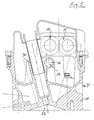
- the internal combustion engine partially shown in the figures as an exemplary embodiment it is one with four valves per cylinder, namely two one and two Exhaust valves, of which only one exhaust valve 1 and one in section according to Figure 1 Inlet valve 2 are shown and the each other with respect to the longitudinal median plane 3 of the Internal combustion engines in which the central axes of the cylinders not shown here lying, facing each other.
- the exhaust valves 1 are used as rocker arms trained valve actuating elements 4, which is pivotable about an axis 5 and are guided on an axle tube as a bearing axis 6 concentric to the pivot axis 5.
- the Inlet valves 2 are also acted on by valve actuators 7, which as Rocker arms are pivotally guided about the axis 5 on the bearing axis 6.
- valve actuation levers 4 and 7 are each for one Cylinders between bearing blocks 8.9, which in turn between successive cylinders, in the illustration according to Figure 2 four cylinders and at the ends of the corresponding Row of cylinders are provided.
- the bearing blocks 8.9 can, which is not shown here, Form components of a common bearing housing that on part 10 of Cylinder head, which is generally designated 11, can be placed and the guides for the Valves 1 and 2 and the corresponding channels, namely the outlet channel 12 and the inlet duct 13.
- the bearing blocks 8.9 are shown as the lower and upper bearing block, the are screwed together on part 10 of the cylinder head. Is possible within the Invention also a division of the cylinder head into a lower and an upper Cylinder head part, the one corresponding to the lower and the upper bearing block Bearing halves are assigned so that separate bearing blocks can be dispensed with. Of the Cylinder head 11 extends continuously over the length of the internal combustion engine.
- bearing blocks 8, 9 support the camshafts 14 and 15, of which the camshaft 14 lies above the bearing designed as an axle tube for the valve actuation levers 4 and 7, the axis of rotation 16 of the camshaft 14 also close to the longitudinal center plane 3 and runs parallel to this.
- the camshaft 14 carries inlet and outlet cams, namely between two bearing blocks 8 two outlet cams 18 adjacent to the bearing blocks 8 and one in the middle between them Inlet cam 19. On gap to the inlet cam 19 and the outlet cam 18 carries the Camshaft 15 intake cam 20.
- the inlet cams 19 and 20 act together on the rollers 27 and 28 one Tap member 21, which is displaceable on the inlet-side valve operating lever 7 is supported.
- the exhaust cams 18 act on the exhaust-side valve operating levers 4 via support rolls 22 mounted thereon.
- the camshaft 14 is in a manner not shown with the crankshaft is connected to the drive and in turn drives via an adjustment gear which is in known type, for example, is designed as a four-wheel coupling gear, the camshaft 15, so that the phase position of the two camshafts 14 and 15 is mutually variable, and with the change in the phase position of these camshafts 14 and 15 I the timing of the intake valves 2.
- the camshaft 14 the intake-open function
- the camshaft 15 the intake-close function controls.
- the valve actuating lever 7 of the intake valves 2 are in the construction described in known manner for the two intake valves 2 each assigned to a cylinder a two-armed lever with two lever arms 23 connected via a cross member 24 joined together, the lever arms 23 sliding guides for the tap 21 with the Form bridge 25, which carries an axis 26 extending perpendicular to the lever arms 23, on the middle support roller 27 and the side support rollers 28 are mounted.
- the Support rollers 27 and 28 act on the central support roller 27 with the cam 19 of the camshaft 14 together, while the laterally outer support rollers 28 via the cams 20 of the Camshaft 15 are acted upon.
- the bridge 25 is also still, as not in detail shown, via springs 29 which between the bridge 25 and the stops not shown Lever arms 23 are clamped in the direction of the camshaft 15, so that a The support rollers 27, 28 bear against at least one of the cams 19 and 20, respectively is ensured.
- camshaft 14 as intake cam 19th and exhaust cam 18 supporting camshaft forms a within the scope of the invention A prerequisite for the most compact possible construction. In this sense there is also one as slim and light as possible design of the valve actuating levers 4 and 7 Axle tube 6 of interest.
- bearing blocks 33 in FIG. 3 form part of a Form a bearing housing, but also with a separate arrangement, an embodiment has proven 3 as appropriate, in which the bearing blocks 33 at the same time recording and holding for the axle tube serving as the bearing 6 for the valve actuation levers 4 and 7.
- the Bearing blocks 33 are provided with a receiving bore 34 for the axle tube, wherein this receiving bore 34 with a via the screw level 35 of the bearing block 33 the lower, the valve head receiving cylinder head part 10 projecting approach 36 is assigned.
Landscapes
- Engineering & Computer Science (AREA)
- Mechanical Engineering (AREA)
- General Engineering & Computer Science (AREA)
- Valve Device For Special Equipments (AREA)
- Valve-Gear Or Valve Arrangements (AREA)
Applications Claiming Priority (2)
| Application Number | Priority Date | Filing Date | Title |
|---|---|---|---|
| DE19745761 | 1997-10-16 | ||
| DE19745761A DE19745761A1 (de) | 1997-10-16 | 1997-10-16 | Variable Ventilsteuerung für Hubkolben-Brennkraftmaschinen |
Publications (2)
| Publication Number | Publication Date |
|---|---|
| EP0909882A2 true EP0909882A2 (fr) | 1999-04-21 |
| EP0909882A3 EP0909882A3 (fr) | 1999-06-09 |
Family
ID=7845743
Family Applications (1)
| Application Number | Title | Priority Date | Filing Date |
|---|---|---|---|
| EP98117307A Withdrawn EP0909882A3 (fr) | 1997-10-16 | 1998-09-12 | Commande variable de soupape pour moteurs à combustion interne et à pistons |
Country Status (3)
| Country | Link |
|---|---|
| US (1) | US6098581A (fr) |
| EP (1) | EP0909882A3 (fr) |
| DE (1) | DE19745761A1 (fr) |
Cited By (3)
| Publication number | Priority date | Publication date | Assignee | Title |
|---|---|---|---|---|
| US6425357B2 (en) | 2000-03-21 | 2002-07-30 | Toyota Jidosha Kabushiki Kaisha | Variable valve drive mechanism and intake air amount control apparatus of internal combustion engine |
| EP1375843A1 (fr) | 2002-06-28 | 2004-01-02 | AVL List GmbH | Moteur à combustion interne |
| AT500600B1 (de) * | 2004-07-20 | 2007-09-15 | Avl List Gmbh | Brennkraftmaschine mit innerer verbrennung |
Families Citing this family (6)
| Publication number | Priority date | Publication date | Assignee | Title |
|---|---|---|---|---|
| DE19959989A1 (de) * | 1999-12-13 | 2001-06-21 | Audi Ag | Lagerung zumindest einer Nockenwelle |
| JP3652598B2 (ja) * | 2000-11-22 | 2005-05-25 | 本田技研工業株式会社 | 内燃機関 |
| US6895925B2 (en) | 2002-09-18 | 2005-05-24 | Daimlerchrysler Corporation | Internal combustion engine having three valves per cylinder |
| DE10314683B4 (de) * | 2003-03-29 | 2009-05-07 | Entec Consulting Gmbh | Variable Ventilhubsteuerung für einen Verbrennungsmotor mit untenliegender Nockenwelle |
| WO2004088094A2 (fr) * | 2003-03-29 | 2004-10-14 | Hydraulik-Ring Gmbh | Dispositif de poussoir a soupape variable utilise pour ajuster les soupapes d'echange de gaz dans un moteur a combustion interne |
| WO2006000004A2 (fr) * | 2004-06-24 | 2006-01-05 | Avl List Gmbh | Moteur a combustion interne |
Citations (2)
| Publication number | Priority date | Publication date | Assignee | Title |
|---|---|---|---|---|
| DE4322480C2 (de) | 1993-07-06 | 1996-05-02 | Meta Motoren Energietech | Vorrichtung zur variablen Ventilsteuerung von Brennkraftmaschinen |
| DE19701203A1 (de) | 1997-01-15 | 1998-07-23 | Daimler Benz Ag | Variable Ventilsteuerung für Brennkraftmaschinen |
Family Cites Families (14)
| Publication number | Priority date | Publication date | Assignee | Title |
|---|---|---|---|---|
| DE2919213A1 (de) * | 1979-05-12 | 1980-11-20 | Daimler Benz Ag | Zylinderkopf fuer eine brennkraftmaschine |
| DE3217203A1 (de) * | 1981-05-15 | 1982-12-02 | Honda Giken Kogyo K.K., Tokyo | Variable ventilsteuerung |
| US4546735A (en) * | 1984-01-23 | 1985-10-15 | Southwest Research Institute | Valve actuator |
| JPS60175807U (ja) * | 1984-05-01 | 1985-11-21 | 本田技研工業株式会社 | 内燃機関におけるsohc型動弁機構の潤滑装置 |
| US4862845A (en) * | 1988-05-10 | 1989-09-05 | Borg-Warner Transmission And Engine Components Corporation | Variable camshaft timing system |
| JP2786699B2 (ja) * | 1989-11-29 | 1998-08-13 | ヤマハ発動機株式会社 | Sohcエンジンの動弁装置 |
| GB9018558D0 (en) * | 1990-08-23 | 1990-10-10 | Ricardo Group Plc | Valve gear for internal combustion engines |
| US5052350A (en) * | 1990-11-02 | 1991-10-01 | King Brian T | Device to combine the motions of two camlobes differentially phased |
| ATE158058T1 (de) * | 1991-04-24 | 1997-09-15 | Donald Charles Wride | Ventilantriebsvorrichtung |
| US5586527A (en) * | 1992-12-30 | 1996-12-24 | Meta Motoren-Und Energie-Technik Gmbh | Device for the variable control of the valves of internal combustion engines, more particularly for the throttle-free load control of 4-stroke engines |
| DE4301453C2 (de) * | 1993-01-20 | 1995-01-05 | Meta Motoren Energietech | Variable Ventilsteuerung von Brennkraftmaschinen |
| JPH0763022A (ja) * | 1993-08-25 | 1995-03-07 | Akira Sakamoto | 吸・排気バルブ開閉構造 |
| US5682854A (en) * | 1994-03-07 | 1997-11-04 | Komatsu Ltd. | Variable compression ratio engine |
| DE19600536C2 (de) * | 1996-01-09 | 2002-08-22 | Meta Motoren Energietech | Vorrichtung zur variablen Steuerung eines Einlaßventils |
-
1997
- 1997-10-16 DE DE19745761A patent/DE19745761A1/de not_active Withdrawn
-
1998
- 1998-09-12 EP EP98117307A patent/EP0909882A3/fr not_active Withdrawn
- 1998-10-15 US US09/173,388 patent/US6098581A/en not_active Expired - Fee Related
Patent Citations (2)
| Publication number | Priority date | Publication date | Assignee | Title |
|---|---|---|---|---|
| DE4322480C2 (de) | 1993-07-06 | 1996-05-02 | Meta Motoren Energietech | Vorrichtung zur variablen Ventilsteuerung von Brennkraftmaschinen |
| DE19701203A1 (de) | 1997-01-15 | 1998-07-23 | Daimler Benz Ag | Variable Ventilsteuerung für Brennkraftmaschinen |
Cited By (3)
| Publication number | Priority date | Publication date | Assignee | Title |
|---|---|---|---|---|
| US6425357B2 (en) | 2000-03-21 | 2002-07-30 | Toyota Jidosha Kabushiki Kaisha | Variable valve drive mechanism and intake air amount control apparatus of internal combustion engine |
| EP1375843A1 (fr) | 2002-06-28 | 2004-01-02 | AVL List GmbH | Moteur à combustion interne |
| AT500600B1 (de) * | 2004-07-20 | 2007-09-15 | Avl List Gmbh | Brennkraftmaschine mit innerer verbrennung |
Also Published As
| Publication number | Publication date |
|---|---|
| EP0909882A3 (fr) | 1999-06-09 |
| DE19745761A1 (de) | 1999-04-22 |
| US6098581A (en) | 2000-08-08 |
Similar Documents
| Publication | Publication Date | Title |
|---|---|---|
| DE69934533T2 (de) | Viertakt-Brennkraftmaschine | |
| DE4320126C2 (de) | Nockenwellenanordnung zur Verwendung in einem Verbrennungsmotor | |
| DE3436426C2 (fr) | ||
| DE3634877C2 (fr) | ||
| DE4039256A1 (de) | Einrichtung zur gleichzeitigen betaetigung zweier gaswechselventile einer brennkraftmaschine | |
| DE69027032T2 (de) | Nockenwellenanordnung für eine Mehrventil-Brennkraftmaschine | |
| DE60122855T2 (de) | Ventilsteuerungseinrichtung für eine Brennkraftmaschine | |
| DE3102905A1 (de) | Wassergekuehlte brennkraftmaschine | |
| DE60200923T2 (de) | Brennkraftmaschine mit Ventilantrieb | |
| DE9406190U1 (de) | Vorrichtung zur gleichzeitigen Betätigung von zumindest zwei Gaswechselventilen | |
| EP0576768A1 (fr) | Dispositif de commande de soupapes pour moteur à combustion interne multicylindre | |
| EP0909882A2 (fr) | Commande variable de soupape pour moteurs à combustion interne et à pistons | |
| DE69024117T2 (de) | Zylinderkopf-Schmiersystem einer Brennkraftmaschine | |
| DE10239224B4 (de) | Ventiltrieb für Doppelnockenwellenmotor mit drei Ventilen | |
| DE3743854A1 (de) | Vierventilsteuerung mit oberen abstuetzelementen | |
| DE19953346A1 (de) | Ventilmechanismus eines Verbrennungsmotors | |
| DE69414557T2 (de) | Zylinderkopfanordnung für eine Mehrventil-Brennkraftmaschine mit obenliegender Nockenwelle | |
| EP0845582B1 (fr) | Commande de soupape pour un moteur à combustion interne équipé de soupapes à levée pour le transfert de charge | |
| DE4331898A1 (de) | System zur Betätigung eines Ventils in einem Motor | |
| DE102008015218B4 (de) | Ventilmechanismus eines Motors | |
| DE19519601A1 (de) | Ventilantriebssytem für eine mehrzylindrige Brennkraftmaschine | |
| DE10358924A1 (de) | Ventilsystem für einen Verbrennungsmotor | |
| DE29724388U1 (de) | Variable Ventilsteuerung für Hubkolben-Brennkraftmaschinen | |
| DE3148720A1 (de) | Ventilsteuerung fuer kolben-brennkraftmaschinen | |
| EP0352580A1 (fr) | Dispositif d'actionnement de soupapes d'un moteur à combustion interne |
Legal Events
| Date | Code | Title | Description |
|---|---|---|---|
| PUAI | Public reference made under article 153(3) epc to a published international application that has entered the european phase |
Free format text: ORIGINAL CODE: 0009012 |
|
| AK | Designated contracting states |
Kind code of ref document: A2 Designated state(s): DE FR GB IT |
|
| AX | Request for extension of the european patent |
Free format text: AL;LT;LV;MK;RO;SI |
|
| PUAL | Search report despatched |
Free format text: ORIGINAL CODE: 0009013 |
|
| AK | Designated contracting states |
Kind code of ref document: A3 Designated state(s): AT BE CH CY DE DK ES FI FR GB GR IE IT LI LU MC NL PT SE |
|
| AX | Request for extension of the european patent |
Free format text: AL;LT;LV;MK;RO;SI |
|
| RIC1 | Information provided on ipc code assigned before grant |
Free format text: 6F 01L 13/00 A, 6F 01L 1/26 B, 6F 01L 1/053 B |
|
| 17P | Request for examination filed |
Effective date: 19990521 |
|
| GRAG | Despatch of communication of intention to grant |
Free format text: ORIGINAL CODE: EPIDOS AGRA |
|
| AKX | Designation fees paid |
Free format text: DE FR GB IT |
|
| GRAG | Despatch of communication of intention to grant |
Free format text: ORIGINAL CODE: EPIDOS AGRA |
|
| GRAH | Despatch of communication of intention to grant a patent |
Free format text: ORIGINAL CODE: EPIDOS IGRA |
|
| 17Q | First examination report despatched |
Effective date: 20000225 |
|
| GRAH | Despatch of communication of intention to grant a patent |
Free format text: ORIGINAL CODE: EPIDOS IGRA |
|
| ITF | It: translation for a ep patent filed | ||
| STAA | Information on the status of an ep patent application or granted ep patent |
Free format text: STATUS: THE APPLICATION IS DEEMED TO BE WITHDRAWN |
|
| 18D | Application deemed to be withdrawn |
Effective date: 20010403 |