EP0910723B1 - Vorrichtung zur beschränkung des biegeradius einer flexiblen rohrleitung - Google Patents
Vorrichtung zur beschränkung des biegeradius einer flexiblen rohrleitung Download PDFInfo
- Publication number
- EP0910723B1 EP0910723B1 EP98912546A EP98912546A EP0910723B1 EP 0910723 B1 EP0910723 B1 EP 0910723B1 EP 98912546 A EP98912546 A EP 98912546A EP 98912546 A EP98912546 A EP 98912546A EP 0910723 B1 EP0910723 B1 EP 0910723B1
- Authority
- EP
- European Patent Office
- Prior art keywords
- support
- stiffener
- flexible pipe
- bearing element
- bearing
- Prior art date
- Legal status (The legal status is an assumption and is not a legal conclusion. Google has not performed a legal analysis and makes no representation as to the accuracy of the status listed.)
- Expired - Lifetime
Links
Images



Classifications
-
- E—FIXED CONSTRUCTIONS
- E21—EARTH OR ROCK DRILLING; MINING
- E21B—EARTH OR ROCK DRILLING; OBTAINING OIL, GAS, WATER, SOLUBLE OR MELTABLE MATERIALS OR A SLURRY OF MINERALS FROM WELLS
- E21B43/00—Methods or apparatus for obtaining oil, gas, water, soluble or meltable materials or a slurry of minerals from wells
- E21B43/01—Methods or apparatus for obtaining oil, gas, water, soluble or meltable materials or a slurry of minerals from wells specially adapted for obtaining from underwater installations
- E21B43/0107—Connecting of flow lines to offshore structures
-
- E—FIXED CONSTRUCTIONS
- E21—EARTH OR ROCK DRILLING; MINING
- E21B—EARTH OR ROCK DRILLING; OBTAINING OIL, GAS, WATER, SOLUBLE OR MELTABLE MATERIALS OR A SLURRY OF MINERALS FROM WELLS
- E21B17/00—Drilling rods or pipes; Flexible drill strings; Kellies; Drill collars; Sucker rods; Cables; Casings; Tubings
- E21B17/01—Risers
- E21B17/017—Bend restrictors for limiting stress on risers
-
- E—FIXED CONSTRUCTIONS
- E21—EARTH OR ROCK DRILLING; MINING
- E21B—EARTH OR ROCK DRILLING; OBTAINING OIL, GAS, WATER, SOLUBLE OR MELTABLE MATERIALS OR A SLURRY OF MINERALS FROM WELLS
- E21B43/00—Methods or apparatus for obtaining oil, gas, water, soluble or meltable materials or a slurry of minerals from wells
- E21B43/01—Methods or apparatus for obtaining oil, gas, water, soluble or meltable materials or a slurry of minerals from wells specially adapted for obtaining from underwater installations
- E21B43/013—Connecting a production flow line to an underwater well head
- E21B43/0135—Connecting a production flow line to an underwater well head using a pulling cable
-
- F—MECHANICAL ENGINEERING; LIGHTING; HEATING; WEAPONS; BLASTING
- F16—ENGINEERING ELEMENTS AND UNITS; GENERAL MEASURES FOR PRODUCING AND MAINTAINING EFFECTIVE FUNCTIONING OF MACHINES OR INSTALLATIONS; THERMAL INSULATION IN GENERAL
- F16L—PIPES; JOINTS OR FITTINGS FOR PIPES; SUPPORTS FOR PIPES, CABLES OR PROTECTIVE TUBING; MEANS FOR THERMAL INSULATION IN GENERAL
- F16L35/00—Special arrangements used in connection with end fittings of hoses, e.g. safety or protecting devices
Definitions
- the present invention relates to a curvature limiting device of a flexible pipe, in particular in the case where the pipe includes a nozzle with a diameter larger than that of the pipe, and more in particular, a device comprising a stiffener intended to equip a flexible pipe in which a hot fluid circulates, the temperature is above 80 ° C.
- Such flexible pipes are used in particular in petroleum exploitation, for the ascent or transportation of oil from an underwater wellhead to a floating platform or equipment such as a floating production boat and Storage Offloading which is designated by the abbreviation FPSO.
- FPSO floating production boat and Storage Offloading
- the curvature limiting device according to the invention is also usable with other types of flexible pipes, in particular in the underwater petroleum development facilities, such as flexible lines with multiple conduits called umbilicals or cables electric.
- a stiffener is mounted in the junction area of the flexible pipe with the end fitting (s) which equip the flexible pipe at its two ends, a terminal nozzle comprising, such that it is described in API RP 17B under the name of "end fitting", on the one hand, a flexible termination member ("end termination"), and other hand, a connecting member ("end connect”) with the pipes to which the flexible pipe is connected, in particular a subsea wellhead and / or a surface support such as a ship or a platform.
- EP 0 296 056 and FR 2538444 show stiffeners used at the foot of the riser.
- a stiffener can also be mounted on the current part of the flexible pipe, away from the end fittings, for example at the edge an intermediate support ("pipe tray") in the case of a flexible pipe riser with a "lazy S” or “Steep S” configuration, as it is described in API RP 17 B, or at the end of a rigid guide tube protecting the upper part of the flexible pipe, as it is shown in Figures 11, 12 and 13 of WO 92/12376 or in EP-565,445 (Coflexip stiffener fitting).
- Such stiffeners are well known. They can be made up by a simple elastic body molded from polyurethane and can alternately understand an internal reinforcement structure as it is described in WO 92/12376 or in GB-A-2 291 686. They can also include means of heat dissipation as well as this is recommended in FR-95 14 114 - unpublished - of the Applicant, and GB-A-2 291 686.
- the heat dissipation means are intended to dissipate a part of the heat at the interface between the elastic body of the stiffener and the flexible pipe, said heat coming from the fluid circulating in said flexible driving. Indeed, it turned out that said heat damaged the plastic material (polyurethane) of the stiffener by hydrolysis in contact with sea water, hydrolysis-leading to a loss of mechanical properties of the stiffener and in particular to a loss of stiffness.
- a stiffener In all cases of use of a stiffener, the latter is, normally placed on the flexible pipe before mounting and fixing the or end fittings, a radial clearance between the flexible pipe allowing to slide the latter along the flexible pipe. After mounting end fittings on the flexible pipe, the stiffener is brought, by sliding, on the corresponding end fitting and fixed to the latter by suitable means which are at least partially described in the prior art documents. Alternatively, if the stiffener is to be installed in running length of the pipe, it is positioned at the place desired by means of temporary or permanent fasteners, such as a collar tight around the pipe.
- each stiffener can have lengths which can be the order of four meters and constitute a load with the terminal nozzle localized up to about three tonnes. This results in problems dimensions, unbalance and handling which severely affect all the implementation operations since the end of manufacturing from the pipeline and its loading on the ship until its installation on the site at sea.
- the passage of the stiffener in the various organs handling of the pipe, such as track tensioners, or curved supports or pulley grooves requires delicate maneuvers and long.
- stiffeners made in two halves which can be assembled at the last moment and assembled around flexible pipe by means such as bolt-on collars, as well as described in FR-2 446 981, but experience has shown that such stiffener is unfit to present, regardless of the bending direction of the driving, mechanical characteristics required.
- the object of the present invention is to remedy the drawbacks mentioned above and to propose a simple and effective solution without compromising the cost of manufacture of the assembly recalled above.
- the subject of the present invention is a device for limiting curvature according to claim 1.
- stiffener (s) can be transported independently of each other and the flexible pipe fitted with its two factory fitted end fittings, in place of the stiffener (s) then being carried out at the installation site without requiring other means than those usually available for installation of the installation of said flexible pipe from the ship of laying, as various pipe accessories are installed, such as buoys.
- maximum diameter of the end fitting we mean the external dimensions of the non-dissociable part of larger dimensions of the end fitting around which the stiffener must pass.
- end fitting includes or is permanently fixed to a flange connection (end connector) with transverse dimensions greater than those of the central body of the nozzle (end termination), these are the dimensions of said flange which constitute the maximum diameter since in such a case, the stiffener must be capable of being slid over said flange connection. It goes without saying that when the end piece does not understand connection flange or if it has been separated from said flange, then these are the external dimensions of the central tip body which define the diameter maximum.
- the diameter maximum will be that of said intermediate body.
- the diameter maximum to consider is the diameter of the organ plus large dimensions above which the stiffener must be slid.
- Another advantage is that we almost completely eliminate congestion, imbalance and handling issues during transport between the manufacturing plant and the production site, at least those which are directly linked to the stiffener (s) since the stiffener (s) are no longer mounted in the factory on the flexible pipe.
- the element of support and support can constitute a wear part that can be changed without difficulty when hydrolysis wear occurs, for example, without require replacement of the stiffener itself, replacement of the support element being particularly facilitated when it is made up of several parts or sectors.
- the support and support element can be mounted on the flexible pipe at the factory or on the operating site when it is made up of several parts.
- Another advantage is that it becomes possible, in case of wear or damage to a stiffener, replace it at the installation site without having to disassemble the terminal tip accessible from the support, such as a platform or a vessel, to which the end of the flexible pipe is attached.
- This advantage is particularly interesting because the tip of replacement and assembly are very expensive and any intervention by this kind at sea greatly increases normal costs due to necessary logistical supports and production stoppages, and also because that changing the tip requires a reduction in the length of the flexible pipe which can be problematic.
- seawater circulation grooves they can be made either on the internal surface of the support and support element, so as to cool, by direct contact, the external skin of the flexible pipe, ie on the surface external of the support and support element for both cooling the surface internal of the stiffener and the external skin of the flexible pipe, by a choice the material used for the manufacture of the support element and support.
- the stiffener having an active front part which supports the flexible pipe in its flexural deformations while limiting the amplitude of these flexions, the support element comprises at least an anterior part on which the active part of the stiffener rests throughout its length and whose front end is at least at the level from the front end of the stiffener and preferably beyond.
- the part front end of the active part of the stiffener is commonly of generally frustoconical shape, the front part of the support element can thus have an end portion extending the stiffener, the outer surface can be either cylindrical or frustoconical in the extension of the external contour of the stiffener.
- the stiffener comprises, a rear part installation, generally cylindrical in shape through which the stiffener is fixed in a mounting support so as to resist bending moments and lateral forces induced by displacements of the flexible pipe as well as, possibly, with the efforts Axial.
- the mounting support may be a rigid member integral with the flexible pipe, such as, typically, a ferrule or clamp tightened around flexible pipe.
- the stiffener is normally fitted around the mounting support or a mounting member integral with this last.
- the mounting support can be an organ rigid independent of the flexible pipe and arranged around it, as than the end portion of a rigid tube.
- the stiffener is normally embedded inside the mounting bracket. In a way typical, a radial clearance between the support element and the internal axial passage of the stiffener or the outer surface of the flexible pipe then allows the latter to slide freely relative to the stiffener and the support Recessed.
- the support element preferably includes a rear fixing part used to immobilize it in the axial direction of the flexible pipe.
- the axial fixing of the support element can be produced by adhesion with the surface outside of the flexible pipe.
- a fixing support having a generally annular in shape, or comprising several assembled elements around the pipe in the manner of circular segments and having a general annular shape corresponding to the configuration of the element support.
- the support for fixing the support element can be arranged at inside of it, and be integral with the flexible pipe, in particular in the form of a metal or plastic collar tight around the pipe, or of a cylindrical bearing surface on the external surface of the nozzle.
- the mounting bracket the support element may also include an element forming part integral or a member integral with the stiffener or the support Recessed.
- the support element can be joined, in its posterior part to the fixing support by any known fixing means, for example a simple membership.
- the blocking of the fixing support in the axial direction of the pipe can be achieved with accessories fixing such as radial pins ensuring the connection with the support or with an intermediate member.
- the support fixing comprises a cylindrical bearing surface capable of being supported on a corresponding cylindrical bearing surface of the rear part of the element support.
- radial clamping means which may be integral with the fixing support or the support element, and which are actuated so as to cancel the radial clearance between said spans cylindrical support and, possibly, to exert a radial tightening force between these staves.
- the stiffener When the stiffener is embedded on a nozzle, its rear part advantageously can be arranged around a span cylindrical at the tip surface, if this span is of a diameter higher than that of the connecting member such as a flange provided for connecting the pipe to its end.
- the support element is then fixed axially to the nozzle via an annular fixing support disposed between the outer surface of the flexible pipe and the stiffener.
- the connecting member is of a diameter greater than that of the body of the endpiece which comprises the termination member of the pipe
- the rear embedding part of the stiffener may be arranged around the body of the nozzle and separated from the latter by a member annular which can be the fixing support used to block the element support with respect to the nozzle.
- the central axial passage of the stiffener presenting an approximately cylindrical surface, the stiffener is then in support, in its rear embedding part, on the fixing support, while the rest of the stiffener is supported on the support element.
- the support element can be fixed on the mounting support either directly, either via a fixing support
- the support may include for this purpose a mounting surface which can be cylindrical, or conical, or in a plane perpendicular to the axis of driving.
- the support element, fixed to the mounting support of the stiffener may have a radial clearance by compared to the flexible pipe, which allows the latter to slide freely in the central passage of the stiffener.
- the support element may consist of an annular member cylindrical monoblock which can have been manufactured separately then put in place around the flexible pipe before fitting the end fittings.
- Such a one-piece support element can also be produced by wrapping a strip or overmolding around the pipe, so that it it is then possible to install the support element after mounting the end fittings on a flexible pipe already completed and tested, or replace if necessary a support element at the site of use of the flexible pipe without having to replace the accessible end fitting.
- the support element comprises a plurality of blocks or sectors capable of being assembled, the assembly thus produced having a general shape approximately cylindrical annular.
- the lateral edges of the blocks constituting their assembly surfaces can typically form radial planes passing through the axis of the flexible pipe, or alternatively, helical surfaces.
- a slight gap separates the edges side of the blocks.
- the circumferential clearance thus obtained has a value chosen according to the diameter of the flexible pipe, diameter which can typically vary between about 30 to 50 mm and about 500 mm.
- the game total circumference obtained by adding the corresponding elementary clearances to each space between blocks can thus vary between approximately 5 mm for small hoses and 30 to 60 mm for larger ones.
- the support element has, beforehand at its final installation, a radial clearance relative to the flexible pipe and relative to the mounting support of the stiffener.
- Blocking in final position of the support element thanks to the fixing support can be made by pressing the rear part of the support element against the flexible pipe and / or the mounting support so as to cancel the radial clearance, while preferably retaining a radial clearance at the level of the front part of the support element.
- the radial clearance, defined by the difference in radii of the two opposite cylindrical surfaces can be a few 1/10 mm for small hoses, and reach 5 to 10 mm for The biggest.
- the invention makes it possible to proceed easily on board the laying vessel, or from the floating support, such as a platform or an FPSO type ship, on which the flexible pipe used as riser.
- the flexible pipe is put in place by unrolling it horizontally above from the deck of the laying ship either from a storage basket, pulling being provided by one or more multi-track linear tensioners, i.e.
- the pipe is then wrapped around 90 ° around an organ over boarding device such as a curved support or a wheel for descend from the outside of the hull to the bottom of the sea.
- the stiffener can then be installed either on the vertical part of the flexible pipe just below the deflector, either on the horizontal part of the pipe, between the tensioners and the deflector member. In this last case, the operation can be facilitated using one of the many known means allowing an accessory such as this to pass around the deflecting member a stiffener although this accessory is relatively rigid and large diameter over a significant length.
- the flexible is installed using a device known as VLS (Vertical Lay System) described in patent EP 478 742.
- VLS Very Lay System
- the stiffener can be brought in the derrick from the deck of the ship to be disposed vertically below the main tensioning means constituted, by example, by a quadrichenille supported by the tower, and in the axis of these last, the tracks can be laterally spread to allow passage the upper part of the stiffener. It is thus possible either to lower through the stiffener the first end fitting and the flexible pipe descending from the top of the tower, i.e. at the end of the installation of the section of pipe concerned, lift vertically with a pulling cable the second end nozzle to pass it from bottom to top with the flexible pipe through the stiffener.
- the remaining stiffener arranged on the bridge to pass through its central passage by the end piece and the end part of the flexible pipe, the latter having been deviated from its vertical direction in the axis of the tower to pass to a horizontal direction.
- the support element mainly comprises a cylindrical annular part in the form of a sleeve, produced in a single block or in several sectors assembled around the flexible pipe.
- the flexible pipe subjected to a high axial load, is curved in taking a curvature which is limited as a function of the stiffness of the stiffener to bending, radial clearances between the support element and the flexible pipe and / or the stiffener cancel on the internal, concave side of the pipe flexible, which can be designated by the lower surface, the wall of the support element being subjected to a more or less significant radial compression effect in this lower surface between the stiffener and the flexible pipe.
- the support element must, moreover, have a sufficient flexibility to be able to support flexible driving in its curvature, and so be, in the case of dynamic applications, able to withstand a large number of alternating tension-compression cycles corresponding to the alternation of the upper and lower positions of the various areas of the support member.
- the support element may include a member in the form of sleeve made of plastic material.
- This material can be homogeneous, in particular a thermoplastic or an elastomer, or cellular, or else be of the composite type comprising fillers such as short fibers or continuous, or nodular charges such as microspheres.
- the support element can, in complement its main mechanical function which is to transmit radial forces between the flexible pipe and the stiffener, present a flexural rigidity which is added to that of the stiffener and can reach up to 1/4 or 1/3 of the stiffness of the stiffener.
- the support element may also include a plurality rigid rings, for example metallic, spaced in the length of the support element and embedded in a matrix of plastic material.
- the support element can have a plurality of articulated annular parts, each part being able to move angularly in relation to the two parts that frame it to follow the bending of the flexible pipe, until reaching a stop limiting the curvature.
- curvature limiters defined as "bend limiters" in API R.P. 17 B
- Rooms hinged annulars may have interlocking U-shaped sections head to tail, or Z-shaped with two circular bearing surfaces of diameters different, or even, for example, have bearings forming a ball joint.
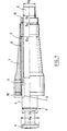
- FIG. 1 there is shown a flexible pipe 1, one end 2 of which is connected to a terminal end piece 3.
- the end piece 3 comprises a connection flange 4 which has external dimensions greater than those of the main body 5 and it is considered to be the part of maximum diameter D M.
- D M the part of maximum diameter
- the flange 4 was smaller, as shown in FIG. 6, it is the body 5 of the nozzle 3 which would be considered to have the maximum diameter.
- a support and support element 6 is arranged around the flexible pipe 1 which has in its current part a predetermined outside diameter, for example D 1 .
- the support and support element has an internal diameter D 2 which is substantially equal to D 1 , so as to be applied with clamping to the flexible pipe 1 after it has been placed in the desired position.
- a stiffener 7 the structure of which is well known and described in the documents cited above, comprises a central through passage 8 whose diameter D 3 is slightly greater than diameter D M so that it can slide on the connection flange 4 and be brought into position after fitting the end piece 3 on the flexible pipe 1.
- the diameter D 3 of the central passage 8 is likewise slightly greater than the outside diameter D 4 of the element 6 so that, when the curvature of the pipe is small or zero, it is possible to slide the stiffener 7 to bring it into the desired position around the element 6.
- the diameters D 1 , D 2 , D 3 and D 4 are chosen so that the ratios (D 2 - D 1 ) / D 2 and (D 3 - D 4 ) / D 4 are less than or equal to 5/100.
- the nozzle 3 is fixedly connected to a support such as a platform, a ship or an underwater structure, and connected to the end of a pipe integral with this support.
- the flexible pipe 1 and the stiffener 7 are curved, at the same time as the element 6 , taking a curvature limited by the opposite reaction by the stiffener, the curvature being able to be cyclically alternated in opposite directions in the case of dynamic applications.
- the element 6 comprises at least one part which is deformable in bending which extends over a length of the flexible pipe included at least between the rear part and the front end of the stiffener 7.
- the stiffener 7, in such a working situation is supported and in continuous support in its lower surface on the element 6, so that the latter can be compressed by said stiffener 7.
- the element 6, the stiffener 7 and the end piece 3 are interconnected by connecting means comprising the embedding members of the stiffener, various embodiments of which are described in the documents of the prior art cited above, as well as the support for fixing the element 6.
- Said connecting means are shown in FIG. 1 schematically and symbolically inside the block shown in dotted lines and referenced 9, particular embodiments being illustrated in particular in FIGS. 7 to 21.
- the stiffener 7 which is adapted to the ambient conditions in which the flexible pipe 1 works, has dimensions, and in particular a length, which are determined as a function of the outside diameter D 1 of the flexible pipe 1 and of the conditions of use, in particular the traction in the flexible pipe and the maximum value that the angle which it makes in its approximately rectilinear part beyond the stiffener relative to the axis of the nozzle 3 can reach.
- the front part of the element 6, on the side opposite to the end piece 3, extends continuously over the entire length of the stiffener 7, the front end of the element 6 preferably being beyond the front end of the stiffener 7 by forming the free end 10.
- FIG. 1 illustrates such a case when, moreover, the maximum diameter D 5 of the main body 5 of the end piece 3 is less than the diameter of the flange 4 constituting the connecting member of the end piece.
- the rear embedding part of the stiffener 7 is advantageously directly in support on the cylindrical outer surface of the main body 5 of the nozzle.
- stiffener 7 and the element 6 must take into account the specificities of each of them.
- an excellent result can be obtained by manufacturing the element 6 in a homogeneous, compact and load-free plastic material.
- the body of the stiffener 7 may consist, in the same way, in a simple volume of plastic material or may also include an internal reinforcement more or less rigid, the material of the support end piece may be identical to the plastic material of the stiffener, for example Adiprene L167 of hardness 95 Shore A and Young's modulus of 70 MPa or Adiprene L100 of hardness 90 Shore A and Young's modulus 50 MPa.
- a hard material whose hardness is 60 Shore D and the Young's modulus of 140 MPa, the material used for the support and support element 6 being able to be l 'Adiprene L167 or L100 of lower hardness.
- Adiprene L167 and L100 materials are shades polyurethane, ADIPRENE® being a brand of DUNLOP.
- Other plastic materials in particular elastomeric or thermoplastics, can be used, for example polyethylene, polypropylene, PVC.
- the support element and of support in a material which is appreciably more flexible and elastic than that of the stiffener provided that the crushing of the material used does not not more than a few percent, 5-10% maximum, under pressure from 10 bars.
- the through passage 8 of the stiffener may not be completely cylindrical for demolding convenience and it is, therefore, slightly tapered, the taper being 1 to 3 ⁇ . It is then used to center the support and support element with respect to the stiffener.
- FIGS 2 to 4 are very schematically represented cooling means provided on the support and support element 6.
- these cooling means can be constituted by passages such as channels made in the wall of the element 6 or on its surface and allowing the circulation of seawater in the length of element 6.
- the first means 11 are formed by grooves 12 formed on the internal face 13 of the support and support element 6, which is opposite the external face of the hose 1, the cooling fluid circulating in said grooves 12 and directly cooling the skin external of said flexible pipe as well as, at least partially, the interior of the stiffener 7 insofar as the thickness of the element 6 is not not very important.
- the second means are identical to those of FIG. 2, at the difference that cooling grooves 12 'are provided on the face external 14 of the support and support element 6, which is opposite the face internal of the stiffener 7 (FIG. 3). With grooves 12 ', the stiffener 7 is cooled directly, as well as the flexible pipe 1 at least partially provided that the thickness of the support and support element (6) is not very important.
- the means cooling are constituted by elongated openings 15 formed in the support and support element 6 and passing through the wall of the element 6 throughout its thickness, said openings 15 communicating with each other through passages 16.
- the openings 15 allow cooling effective of the stiffener 7 and the flexible pipe 1.
- the grooves 12 or 12 ′, or the openings 15 and the passages 16 can be oriented longitudinally, parallel to the axis of flexible driving. They can also have a general shape helical.
- the support and support element 6 can be produced in a single piece, as shown in Figure 1 or in several sectors.
- a support and support element 6 for example in three distinct blocks constituted by three identical sectors 17 which form, once assembled around the flexible pipe 1, an annular structure cylindrical. This allows installation in situ at the installation site and using the flexible pipe and being able to replace it in situ of element 6 in the event of wear or damage.
- this further reduces the costs of manufacturing by reducing the cross-sectional dimensions of the part to be manufactured.
- the circumferential clearance which can be achieved between the different blocks can be determined in such a way as to favor the establishment and the good operation of the device.
- the handling and transportation of the flexible pipe are facilitated by the fact that the pipe is bare, without element 6 already mounted.
- the support and support element 6 could be produced in two semi-cylindrical parts or in sectors whose number is greater to 3.
- FIG 6 there is shown a stiffener 7 with the element of support 6, arranged around the flexible pipe 1 at a distance from the end piece terminal 3.
- the stiffener 7 is rigidly fixed on a mounting support 19 or on mounting members integral with such a support, the support being integral with a marine structure such as a platform fixed or floating, a ship, or an underwater structure such as a buoy or a fixed submerged structure.
- the mounting support 19 can be find in the immediate vicinity of terminal tip 3, but it is normally distant from the end piece by a distance which may be several tens or several hundred meters.
- the nozzle 3 is arranged in an accessible manner on a platform or a ship or in the upper part of a box ("turret") around which a ship can turn freely while remaining anchored from of the box, or by remaining immobilized by dynamic positioning, the flexible 1 descending from the tip 3 through the marine structure in a vertical or oblique direction.
- the mounting support 19 is attached to the marine structure where the flexible pipe 1 exits the lower part of the marine structure to cross the slice of water direction of the bottom, typically presenting a chain configuration.
- the device advantageously comprises a fixing support 20 of the support element 6 which is, on the one hand, disposed at the rear and rendered integral with the support element 6 and, secondly, preferably fixed on the mounting support 19, or possibly on the flexible pipe 1.
- the flexible pipe 1 can be secured to the support member 6 and the fixing support 20.
- the device according to the invention advantageously allows to leave the flexible pipe 1 the possibility of sliding axially with respect to the stiffener 7 and to the mounting support 19.
- the sliding is made possible by a radial clearance between the flexible pipe 1 of outside diameter D 1 on the one hand and, on the other hand, the assembly constituted by the fixing support 20 and the support element 6 of internal diameter D 2 , the fixing support 20 then being secured to the mounting support 19 and independent of the flexible pipe .
- the sliding can be obtained by a radial clearance between the fixing support 20 and the support element 6 of outside diameter D 4 on the one hand and, on the other hand, the mounting support 19 and the stiffener 7 of internal diameter D 3 , the fixing support 20 then being secured to the flexible pipe 1.
- the mounting support 19 is a resistant rigid piece, typically made of steel, comprising a cylindrical central part whose internal surface has a diameter slightly greater than the external diameter D 4 of the support element 6 and constitutes the extension of the internal passage. axial of the so-called active front part of the stiffener 7.
- the cylindrical part of the support 19 has a front portion 21 whose external surface constitutes a bearing surface for the rear embedding part of the stiffener 7 and extends over a sufficient length to correctly ensure the relative positioning and embedding of the flexible pipe 1 and the stiffener 7 through the support element 6.
- said cylindrical part of the embedding support 19 further comprises a rear portion 22, the inner surface of which constitutes a bearing surface for the fixing support 20 of the element 6.
- Fixing accessories such as radial pins ensure the locking, in particular in the axial direction, of the fixing support 20 of the element 6 relative to the mounting support 19.
- the mounting of the stiffener on the support 19 is preferably consolidated by blocking and fixing, by known means, the rear of the stiffener 7 on the support 19 by known fixing means, as illustrated schematically in Figure 6 in the form of a flange 23 secured to the support 19.
- the embedding support 19 comprises in its part peripheral, symbolically illustrated in Figure 6 by the flange 24, fixing areas or members (not shown) for fixing it rigidly to the marine structure by means of assembly known mechanics such as screws, bolts, articulated collars, latches, etc.
- the mounting support 19 can be produced in several blocks which can be assembled around the flexible pipe 1 in the manner of a segmented collar.
- the support 19 can be in one piece, the internal diameter of its cylindrical part being slightly greater than the maximum diameter D M of the end fitting around which the stiffener 7 must pass. In the case of FIG. 6, this diameter D M is equal to the diameter D 5 of the main body of the nozzle 3, the diameter D 6 of the flange 4 being less than the diameter D 5 .
- the device thus produced by assembling said two sets is then temporarily immobilized at the place provided on the flexible pipe 1.
- the immobilization of said device can be achieved by connecting it to a collar clamped on the flexible pipe 1 or at the end piece 3 by means of temporary joining which can be broken or released from various ways, especially by breaking under the effect of sufficient traction pressure exerted on the flexible pipe or by mechanical means any acting directly on the means of temporary securing and operated by remote control or by plunger or from an ROV (Remote Operated Vehicle).
- ROV Remote Operated Vehicle
- the next step is to unwind the flexible pipe 1 from of the laying vessel by the so-called "pull-in" procedure, the nozzle 3 being, typically connected to an operating cable, operated from a winch installed on the marine structure to which the end piece 3 must be connected.
- the end piece 3 thus reaches an opening in the lower part of the marine structure, advantageously equipped with guide means such as a bell mouth organ.
- guide means such as a bell mouth organ.
- the width dimensions of the mounting support 19 (such as the outside diameter of the flange 24 in the schematic and symbolic representation of FIG.
- the support fixing 20 is thus immobilized on the annular wall defining said opening, respectively complementary ranges, typically radial or conical, then being in abutment against each other under the effect of the traction exerted on the control cable.
- Locking means are then actuated to directly block the mounting support 19 in the opening of the marine structure.
- the means of solidarity are then broken or released, which frees the flexible pipe 1 relative to the embedding device comprising the stiffener 7, the support element 6, the fixing support 20 and the mounting support 19, this embedding device being henceforth made integral with the marine structure.
- the first end pull-in operation of the flexible pipe 1 ends with the connection of the connection 4 of the nozzle 3 with the corresponding end of a pipeline attached to the marine structure.
- the operation of laying the flexible pipe 1 can then be continue by continuing to unroll it from the laying vessel which moves away from the marine structure as, typically, the flexible pipe is laid on the bottom.
- FIGS. 7 to 21 illustrate various specific examples of realization of a mounting device according to the invention.
- the end piece 3 constitutes the mounting support on which the stiffener 7 is mounted.
- FIG. 7 illustrates a case where the maximum diameter D M of the end piece 3 is equal to the diameter D 5 of the main body 5 of the end piece.
- the central passage 8 is delimited by a rigid cylindrical wall 26, preferably metallic.
- the stiffener 7 also comprises, in a manner also known, a rigid rear wall, constituted by an annular radial metal plate 27 which is integral with the internal cylindrical wall 26, as well as an internal reinforcement 28 embedded in the elastomeric material of the stiffener .
- the support element 6 also includes a rear end portion 29 cylindrical but thinner than the main part of the element 6. Outside, said end portion 29 is supported on the stiffener in the area where the latter is made rigid by the cylindrical wall metallic 26. Inside, the end portion 29 is supported on a cylindrical middle part 30 of the fixing support 20, so that the end portion 29 of element 6 is held between the wall 26 of the stiffener 7 and the middle part 30 of the support 20.
- the metal wall 26 being thus resting on the main body 5 of the end piece and on the end part 29 of the support element 6, it is advantageously extended towards the front so that its front end 31 is in front of the front end 32 of the fixing support 20.
- the means ensuring the blocking of the rear end 29 of the element 6 are advantageously supplemented by two radial annular elements of the fixing support 20, located on either side of its middle part 30, one of the radial elements 33 being at the rear and facing outward, and forming an axial stop for the end part 29 of element 6, and the other radial element 34 being at the front and facing inwards, so that the mounting bracket 20 has an S or Z-shaped section.
- the fixing support 20 is mounted on the end piece 3 by through a connecting piece 35 constituted by a metal ring comprising, on the one hand, a radial bearing 36 bearing on a bearing corresponding front of the main body 5 of the endpiece and fixed to the latter by means such as a plurality of screws or bolts 37, and on the other hand, a cylindrical part 38.
- the cylindrical part 38 is in radial support, on the one hand by its outer surface on the cylindrical part 30 of the fixing support 20, and on the other hand, by its inner surface on the outer surface of flexible pipe 1, the wall of which is illustrated schematically with an outer sheath 39, an armor 40 and a part interior 41.
- the fixing support 20 is axially fixed on the end piece 3 through the connecting piece 35 thanks to accessories fixing such as radial pins 42.
- the axial fixing of the element support support 6 can be produced by pins 42, but it can advantageously be consolidated by adhering to the interface 43 of the rear part of the support element 6, bearing on the cylindrical part end 30 of support 20.
- the stiffener 7 is, moreover, blocked on the end piece 3, so known, by a mounting member constituted by a metal flange 18 which has a portion in the form of an annular radial plate 44 bearing on the rigid rear wall 27 of the stiffener 7 and a cylindrical part 45 in support on the main body of the nozzle.
- axial fixing is achieved by means such as nuts or bolts 46 blocking the free end of the frame 28 on the radial part 44 and by embedding of the cylindrical part 45 in a groove 47 formed in the outer surface of the main body 5 of the nozzle.
- the flange 18 is made in at least two parts, like a segmented collar, so that be able to be put in place around the nozzle 3 after the stiffener 7 has been passed around the nozzle and the support element 6.
- the part cylindrical 45 of the flange 18 being thus housed in the groove 47, the flange is then securely assembled, for example by bolting.
- the operation is completed by backing up the stiffener until contact between the radial plates annulars 27 and 44 and by fixing the stiffener with the fixing means axial 46.
- the stiffener is mounted on a nozzle whose main body 5 has an outside diameter D 5 less than the diameter D 6 of the flange 4.
- the device for mounting the stiffener and its support element illustrated in FIG. 8 comprises a connecting piece 35 ′ comprising a front cylindrical part 38 bearing on the flexible pipe 1, as in the case of the example illustrated by Figure 7.
- the connecting piece 35 'further comprises a rear part of revolution 48 whose inner surface is supported on the main nozzle body 5 and whose outer surface has a diameter corresponding to the outer diameter D 4 of the support element 6, slightly greater than the diameter D 6 of the flange 4, the stiffener 7 being in abutment, from the rear towards the front, on the connecting piece 35 'and on the support element 6
- the connecting piece is produced in at least two parts able to be assembled around the body 5 of the end piece, the axial locking being ensured by the penetration of a projection 49 of the rear part 48 into a groove 50 of the main body.
- the connecting piece 35 'thus ensures the axial locking of the fixing support 20 to which it is linked by pins 42.
- the fixing of the stiffener 7 on the end piece 3 is ensured by means of the connecting piece 35'.
- the flange 18 made of at least two assemblable elements is, on the one hand, secured to the stiffener 7 by the means 46 and, on the other hand, immobilized on the connecting piece 35 'by the penetration of a annular part in relief 45 in a groove 51 on the surface of the part 35 '.
- the device illustrated in FIG. 9 does not include any part connection such as parts 35 or 35 ', blocking of the fixing support 20 on the tip being provided by means of a mounting member such that a flange 18 'produced in at least two parts which can be assembled around the tip on which it is immobilized by penetration of a part internal cylindrical 45 'in a groove 47 on the surface of the main body 5 from the mouthpiece.
- the fixing support 20 is fixed to the flange 18 'by means 52 such as screws, the stiffener 7 also being fixed to the same flange 18 ' by means 46 already described.
- the fixing support 20 having a front radial element 34 in axial support on the anterior peripheral bearing of the main body 5 of the end piece, it will be noted that, unlike the examples in FIGS. 7 and 8, the end portion 29 of element 6 is here in radial abutment on the body 5 via the cylindrical middle part 30 of the support fixing 20.
- FIGS 10 to 16 illustrate various examples of mounting the stiffener 7 on a marine structure made so that the connection between the stiffener 7 and the flexible pipe 1 is made via a support element 6 according to the invention.
- the marine structure is represented schematically by the edges 53 of the opening in the marine structure, opening to which the stiffener must be fixed and through which must pass the flexible pipe 1.
- the stiffener is fixed on the edges 53 of the opening by means of a mounting support 19 which is produced in the form of a rigid part of revolution 19 comprising flanges 23 and 24 respectively fixed to the stiffener 7 and to the edges 53 of the opening by means 46 'and 54 such as screws or bolts.
- Figures 10 to 13 illustrate devices where the support 6 is fixed inside the installation support, in particular in in the axial direction, the flexible pipe 1 possibly being free to slide axially relative to the support element 6.
- the embedding support 19 comprises a cylindrical part whose internal surface is an extension of the internal surface of the passage 8 inside the stiffener and is supported on the element of support 6.
- Said cylindrical part comprises a central portion 55 between the flanges 23 and 24 which bears on the rear end part 29 of the support element 6.
- the surface of the central passage 8 is delimited by a rigid cylindrical element 26 integrated into the stiffener, the internal diameter of which is greater than the diameter D 3 of the stiffener, so that the cylindrical part of the mounting support has a front portion 21 disposed in the annular space between the support element 6 and the rigid element 26, this arrangement having the effect of reinforcing the embedding of the stiffener 7 on the embedding support 19.
- the support element 6 is fixed to the mounting support 19 by means of the fixing support 20, the part rear end 29 of the support element being internally supported on a cylindrical part 30 'constituting the anterior zone of the fixing support 20.
- the support element 6 is retained axially with respect to the support of fixing 20 by any known means, for example, in a simple and advantageous, by bonding the interface 43 between the rear part 29 of element 6 and the front cylindrical part 30 ′ of the fixing support 20.
- the fixing support 20 is fixed on the mounting support 19 by means of a connecting piece 56 made in at least two sectors so that it can be assembled around of a rear part of revolution 57 of the fixing support 20 and being in radial support on the latter.
- Part 56 has a shaped section square with a cylindrical part 58 embedded in a groove 59 at the surface of the rear part 57 of the support 20, and a radial part in form of flange 60 locked against the mounting support 19 by assembly means 61 such as screws or bolts.
- the mounting support 19 illustrated in FIG. 11 comprises a cylindrical part having a rear portion 22 bearing on the rear part 57 of the fixing support 20 which can thus be fixed to the support of embedding 19 by assembly means 62 of any known type, by example of screws or bolts.
- the mounting of the fixing support 20 is ensured by a radial annular connecting piece such as a flange 63, preferably carried out in at least two assemblable sectors, and which is fixed both on the fixing support 20 and on the mounting support by assembly means 64 and 61 'of any known type, such as screws or bolts.
- the mounting of the mounting bracket illustrated in Figure 13 is obtained by assembling it with the stiffener 7 by means of assembly means such as a flange 65.
- the flange 65 is blocked at the same time, by fixing means 66 and 67, on the fixing support 20 and on the metal plates 26 and 27 which constitute the internal and rear borders of the posterior part 25 of the stiffener 7.
- Figures 14, 15 and 16 illustrate exemplary embodiments comprising a support element 6 immobilized on the flexible pipe 1, the assembly thus formed can slide axially, if necessary, to the interior of the assembly constituted by the stiffener 7 and the support 19.
- the support element 6 is blocked axially on the flexible pipe via the mounting bracket 20, with which it is joined, for example, by adhering its interface 43 with the front cylindrical part 30 'of the fixing support 20.
- the support 20 is immobilized on the flexible pipe by means of a collar clamp 68 consisting of at least two parts which are assembled at the same time around the flexible pipe 1 and the fixing support 20, then tightened, by means such as bolts 69 so as to lock the collar 68 on the flexible pipe and to anchor it on the support 20, the anchoring can be ensured by giving the opposite ends of the collar 68 and the support 20 nested shapes causing an axial snap as illustrated in figure 14.
- FIG. 15 illustrates a simplified embodiment, the element of support 6 being directly immobilized on the flexible pipe by bonding of the interface 70 of the posterior part of its inner surface with the outside surface of the pipe.
- FIG. 16 illustrates another embodiment close to that in FIG. 15, the blocking of the rear part of the support element 6 being achieved by a purely mechanical clamping effect around the flexible pipe 1.
- the support element is made, at least in its part posterior, in the form of a plurality of sectors separated by slits 100 and which can be pressed against each other so as to be pressed against the flexible pipe 1 in the manner of a segmented collar, the tightening can be achieved by any known means, such as bolts 71.
- FIG. 17 illustrates another embodiment according to which the support element 6 is also immobilized on the flexible pipe, the stiffener 7 being mounted on a nozzle 3, as in the case of FIG. 7.
- the support element is locked by tightening on the pipe flexible 1 of a collar 72 which is arranged in an open annular recess in the outer surface of element 6.
- FIG. 18 illustrates another embodiment according to which the support element 6 is fixed from the inside to the mounting support 19.
- the fixing support 20 ′ has a front part 73 whose external surface 75 is conical and not not cylindrical as is the case for the front part 30 ′ of the examples of FIGS. 10, 11, 12, 13 and 14.
- the internal surface of the rear part of the mounting support 19 has a conical bearing 74.
- the assembly constituted by the stiffener 7 and the mounting support 19 is moved forward to release the rear part of the support element 6.
- the fixing support 20 ' is then pushed forward, so that the bearing 75 which is at the front of the support 20', acts in the manner of a dudgeon by gradually lifting the element 6, the rear part of which takes a conical configuration eva sée as illustrated in Figure 18b, the progression of the support 20 'forward, that is to say to the right of Figure 18, being stopped when a radial bearing 76 of the fixing support 20' reaches axial stop against the rear end of the support element 6. In this situation, the rear part of the support element 6 projects beyond the outside with respect to its cylindrical surface of diameter D 4 .
- the cylindrical seat 101 of the fixing support 20 ′ is built in inside the embedding support 19, the conical bearing 74 of the support fastener 20 'driving inward the part of the support element which projects beyond the internal diameter of the mounting support 19, so that the rear end part 29' of the support element 6 is tightly clamped and retained between the mounting support 19 and the front part 73 of the fixing support 20 '( Figure 18c).
- the anchoring of the part 29 ′ of the element 6 can be reinforced by making striations or undulations on a part 77 of the internal surface of the mounting support 19. Obviously, the rear part 29 ′ of the element support 6 can also be pressed against the internal surface of the stiffener 7.
- FIG. 19 illustrates another embodiment close to that of Figure 7, the connection between the fixing support 20 and the nozzle 3 being performed by a different process which is particularly suitable in the hoses with relatively small internal diameter, of the order of 50 mm to 120 mm.
- a 35 "connecting piece is previously fixed to the end piece 3 by means 37.
- the facing surfaces of the front part 30 "of the connecting piece 35 "and support 20 have, on part of their length, complementary threads 78, so that the locking of the support 20 on the nozzle 3 via the part 35 "is produced in rotating the assembly formed around the axis of the flexible pipe by the support 20 and the support element 6 until the screw 78 is completely tight.
- the element of support has a sufficiently high level of resistance to deformation in flexion to be able to play a role of stiffener in addition to stiffener 7.
- the stiffener 7 is mounted on a mounting support 19.
- the element 6 'filling at the times the role of support and support for the main stiffener 7 and stiffener for flexible pipe 1 is securely fixed by means 79 to a member 80 playing both the role of fixing support for the element 6 'and additional mounting bracket, itself positioned with precision inside the mounting bracket by means such as machined cylindrical surfaces 81.
- the efficiency of the support element 6 'in its additional stiffening function can be increased by a reinforcement internal 82, as, for example, described in patent WO 92/12376.
- the support internal embedding 80 advantageously comprises a front part cylindrical 83 on which the rear part of the element 6 'is in support.
- the frame 82 comprises elongated elements which are subjected to tensile or compressive forces depending on whether they are on the side upper or lower side depending on the direction in which the pipe flexible is curved.
- the rear ends of the elongated elements of the frame 82 pass through a front part 84 of the mounting support internal 80 and are blocked by fixing means such as welds 79 or bolts so as to ensure the recovery of longitudinal forces of traction and compression by the internal support 80.
- fixing means such as welds 79 or bolts
- the support embedding is constituted by the tip 3; in this case the outer surface of the internal mounting support 80 constitutes a contact surface cylindrical resting on a corresponding reinforced part of the stiffener, the internal embedding and fixing support 80 being moreover fixed by embedding on the front face of the end fitting 3.
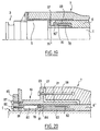
- the support element 6 includes locking elements limiting the curvature of the flexible pipe at a determined maximum value.
- the assembly constituted by the combination of the stiffener 7 and the element of support 6 " is therefore both a stiffener and a curvature limiter (" bend stiffener “and” bend limiter "according to API RP 17B definitions).
- the locking elements comprise a set of nested rings, the cross section of which is U-shaped, the opening being alternately oriented towards the outside for the inner rings 88 and towards the inside for the outer rings 89.
- curvature limiters of the so-called "vertebrae" type
- the longitudinal distance between neighboring rings is limited between given minimum and maximum values.
- the minimum radius of curvature is obtained by mutual support of the lateral edges of the elements 88 on the lower surface side and, on the upper surface side, by mutual support of a lateral part of a ring 88 and of a lateral part of a ring 89.
- the lateral parts of the rings 88 and 89 advantageously comprise an annular housing so as to be able to accommodate annular elements of elastomeric material 90 and 91 disposed respectively between the lateral edges opposite the elements 88 and in each space between a lateral part of a ring 88 and a lateral part of a ring 89.
- the blocking of the flexible pipe 1 at its minimum radius of curvature is thus ensured progressively and without shock, by compression of the rings 90 on the lower side and the rings 91 on the upper side, until contact with the bearing surfaces facing the rings 88 and 89 respectively.
- FIG. 21 illustrates the device in its limit configuration, the flexible pipe 1 having, in the area covered by the support and curvature limiting element 6 ", a radius of curvature equal to its minimum value R m .
- the internal rings 88 being similar to each other, as are the external rings 89, the limit value of the angle which the axes of two contiguous rings of the same type can make between them, two internal rings 88 for example , has a given value illustrated by the angle 2 ⁇ in FIG. 21.
- this angle could vary in the length of the device if the various rings had different dimensions from the rear to the front of the device. the successive rings add up, so that the axis of the flexible pipe at the location of the front part of the element 6 "is deviated by an angle ⁇ relative to the axis of the end fitting 3 .
- the rings 88 and 89 are made of hard material and mechanically resistant, especially metallic, the choice of metal depending in particular on specific corrosion conditions, or made of plastic, especially fiber-reinforced plastic. Rings 89 are preferably made of several elements can be assembled, for example into two half-rings. In the case of the example in FIG. 21, the stiffener 7 is mounted on a terminal end piece 3, the general arrangement being similar to that of the example in FIG. 8.
- Element 6 "combining the support function of the stiffener 7 and that of limitation of the curvature is fixed on the end piece 3 by a connecting member 35 '' ', the front part of which has a clip-on profile, with a part lateral relief defining a part in a bowl, the outline of which is similar to that of a half of a locking ring, for example a ring 89 in the case illustrated here.
- the connecting element 35 '' ' is made up of several assemblable sectors, for example two halves which can be assembled with bolts 92.
- the surface inside of element 35 '' ' has a raised part 49 engaged in an annular housing 50 on the surface of the main body 5 of the nozzle.
- the 6 "element consists of a set of rigid rings, it does not has no mounting support such as support 19 used in the case of various variants of support element 6 mainly consisting of plastic material, and it is directly attached to the connecting piece 35 '' ' by stapling between the rearmost ring of the 6 "element, for example an internal ring 88, and the front part of the element 35 ", which has then the same stapling profile as the outer rings 89.
- the stiffener 7 is passed around the element 6 "and the link member 35 '' 'and fixed to the nozzle 3 by a flange 18 whose internal edge is housed in a recess annular 51 on the surface of the connecting member 35 '' '.
- a support and support element of the stiffener 7 and blocking of the curvature similar to the element 6 "of the figure 21 can be used in the case where the stiffener is mounted on a mounting support 19 remote from the end fittings. Fixation such an element 6 "on the mounting support 19 can be done by through a link member 35 '' 'which is attached to the element 6 " by stapling in the same way as illustrated in FIG. 21.
- the connecting member 35 '' ' being arranged, in the radial direction, between the flexible pipe 1 and the installation support 19, it can be fixed to the installation support by means similar to those described above for assembling the part posterior 57 of the fixing support 20 with the mounting support.
- Another advantage of the present invention lies in the fact that the stiffener can be mounted on the flexible pipe after performing pressure tests and this, when leaving the factory, when the pipe flexible begins to be implemented in storage means such as baskets on the laying ship.
- the present invention is also advantageous in the case of flexible pipe with very large end pieces.
- the embodiment shown in the can be implemented.
- Figure 20 which allows curvature limiting devices extremely high performance that cannot be achieved with stiffeners manufactured with existing industrial means. It is so obvious that it is not beyond the scope of the present invention in the case where the stiffener would be installed before fitting the end piece.
Landscapes
- Engineering & Computer Science (AREA)
- Life Sciences & Earth Sciences (AREA)
- Mining & Mineral Resources (AREA)
- Geology (AREA)
- Geochemistry & Mineralogy (AREA)
- Environmental & Geological Engineering (AREA)
- Fluid Mechanics (AREA)
- Physics & Mathematics (AREA)
- General Life Sciences & Earth Sciences (AREA)
- Mechanical Engineering (AREA)
- General Engineering & Computer Science (AREA)
- Supports For Pipes And Cables (AREA)
- Details Of Indoor Wiring (AREA)
- Shaping Of Tube Ends By Bending Or Straightening (AREA)
- Branch Pipes, Bends, And The Like (AREA)
- Duct Arrangements (AREA)
- Protection Of Pipes Against Damage, Friction, And Corrosion (AREA)
- Length Measuring Devices With Unspecified Measuring Means (AREA)
- Investigating Or Analyzing Materials By The Use Of Magnetic Means (AREA)
- Bending Of Plates, Rods, And Pipes (AREA)
- Flexible Shafts (AREA)
- Electric Cable Installation (AREA)
Claims (41)
- Krümmungsbegrenzungsvorrichtung für flexible Rohrleitung (1), die mit Endansatzstücken (3) versehen ist, die an den beiden Enden der flexiblen Rohrleitung angeordnet sind, und wenigstens eine Aussteifung (7), die über eine Länge der flexiblen Rohrleitung angeordnet ist und mit einem hinteren Teil an einem Einbauträger befestigt ist, und ein Abstützelement (6, 6', 6") für die Aussteifung (7), das zwischen der flexiblen Rohrleitung (1) und der Aussteifung (7) angeordnet ist und wenigstens einen biegeverformbaren Abschnitt enthält, der sich über eine Länge der flexiblen Rohrleitung erstreckt, die sich zwischen dem hinteren Teil und dem vorderen Ende der Aussteifung befindet, umfaßt, dadurch gekennzeichnet, daß die Aussteifung einen Innendurchmesser besitzt, der größer als der maximale Außendurchmesser (DM) eines der Endansatzstücke (3) ist, derart, daß die Aussteifung (7) um das Endansatzstück (3) gleiten kann.
- Vorrichtung nach Anspruch 1, dadurch gekennzeichnet, daß das Abstützelement (6) um die flexible Rohrleitung angeordnet wird, bevor wenigstens eines der Endansatzstücke (3) montiert wird.
- Vorrichtung nach Anspruch 1 oder 2, dadurch gekennzeichnet, daß der Innendurchmesser und der Außendurchmesser des verformbaren Abschnitts des Abstützelements im Betrieb im wesentlichen gleich dem Außendurchmesser der flexiblen Rohrleitung bzw. dem Innendurchmesser der Aussteifung sind.
- Vorrichtung nach einem der Ansprüche 1 bis 3, dadurch gekennzeichnet, daß der Einbauträger durch ein Endansatzstück gebildet ist.
- Vorrichtung nach Anspruch 4, dadurch gekennzeichnet, daß das Endansatzstück (3) einen Hauptkörper (5) umfaßt, der einen Außendurchmesser aufweist, der gleich dem maximalen Durchmesser ist, und daß das Abstützelement (6, 6', 6") vor dem vorderen Ende des Hauptkörpers (5) angeordnet ist.
- Vorrichtung nach Anspruch 4, dadurch gekennzeichnet, daß das Endansatzstück (3) ein Verbindungsorgan (4) umfaßt, das einen Außendurchmesser besitzt, der gleich dem maximalen Durchmesser ist, und daß das Abstützelement (6, 6', 6") einen hinteren Teil (29) umfaßt, der um den Hauptkörper (5) angeordnet ist.
- Vorrichtung nach Anspruch 4, dadurch gekennzeichnet, daß das Endansatzstück (3) ein Verbindungsorgan (4) umfaßt, das einen Außendurchmesser aufweist, der gleich dem maximalen Durchmesser ist, und daß das Abstützelement (6, 6', 6") mit einem ringförmigen Organ (35', 35") fest verbunden ist, das zwischen dem Hauptkörper (5) des Ansatzstücks und der Aussteifung (7) angeordnet ist.
- Vorrichtung nach einem der Ansprüche 1 bis 3, dadurch gekennzeichnet, daß der Einbauträger durch ein Einbauteil (19) gebildet ist, das von dem Endansatzstück (3) verschieden und um die flexible Rohrleitung angeordnet ist.
- Vorrichtung nach Anspruch 8, dadurch gekennzeichnet, daß das Abstützelement (6, 6', 6") am Einbauträger (19) befestigt ist und ein radiales Spiel in bezug auf die äußere Oberfläche der flexiblen Rohrleitung aufweist, so daß zwischen dem Abstützelement (6, 6', 6") und der flexiblen Rohrleitung eine relative longitudinale Bewegung möglich ist.
- Vorrichtung nach einem der vorherigen Ansprüche, dadurch gekennzeichnet, daß das Abstützelement (6, 6', 6") bei einem Druck von 10 Bar einen Stauchungsgrad von weniger als 10 % aufweist.
- Vorrichtung nach einem der vorhergehenden Ansprüche, dadurch gekennzeichnet, daß das Abstützelement (6, 6', 6") aus einem flexiblen Kunststoff besteht.
- Vorrichtung nach Anspruch 11, dadurch gekennzeichnet, daß das Abstützelement (6, 6', 6") eine Shore-A-Härte von mehr als 30 aufweist.
- Vorrichtung nach einem der vorherigen Ansprüche, dadurch gekennzeichnet, daß das Abstützelement (6, 6', 6") aus mehreren Sektoren (17) gebildet ist, die um die flexible Rohrleitung angeordnet sind.
- Vorrichtung nach einem der Ansprüche 1 bis 12, dadurch gekennzeichnet, daß das Abstützelement (6, 6', 6") durch eine Muffe gebildet ist, die auf seiten des hinteren Teils der Aussteifung mit Schlitzen (100) versehen ist.
- Vorrichtung nach einem der vorhergehenden Ansprüche, dadurch gekennzeichnet, daß sie außerdem Wärmeaustauschmittel umfaßt.
- Vorrichtung nach Anspruch 15, dadurch gekennzeichnet, daß die Wärmeaustauschmittel durch Kanäle (12, 12') gebildet sind, in denen Meerwasser zirkuliert.
- Vorrichtung nach Anspruch 16, dadurch gekennzeichnet, daß die Kanäle durch Rinnen (12) gebildet sind, die in der inneren Oberfläche des Abstützelements ausgebildet sind.
- Vorrichtung nach Anspruch 16, dadurch gekennzeichnet, daß die Kanäle durch Rinnen (12') gebildet sind, die in der äußeren Oberfläche des Abstützelements ausgebildet sind.
- Vorrichtung nach einem der vorhergehenden Ansprüche, dadurch gekennzeichnet, daß sie einen Befestigungsträger (20, 20', 80) umfaßt, der sich auf der flexiblen Rohrleitung und auf dem Einbauträger (3, 19) abstützt, wobei der Befestigungsträger einerseits am Abstützelement (6, 6', 6") und andererseits am Einbauträger (3, 19) axial befestigt ist, so daß das Abstützelement in bezug auf den Einbauträger unbeweglich ist.
- Vorrichtung nach Anspruch 19, dadurch gekennzeichnet, daß das Abstützelement (6, 6') einen zylindrischen hinteren Teil (29) umfaßt, der sich an einem zylindrischen Teil (30, 30', 83) des Befestigungsträgers (20, 80) abstützt.
- Vorrichtung nach Anspruch 22, dadurch gekennzeichnet, daß der zylindrische hintere Teil (29) des Abstützelements (6, 6') außerhalb des zylindrischen Teils (30, 30', 83) des Befestigungsträgers (20, 80) angeordnet ist.
- Vorrichtung nach einem der Ansprüche 20 oder 21, dadurch gekennzeichnet, daß die Befestigung des Abstützelements (6) am Befestigungsträger (20) in axialer Richtung der flexiblen Rohrleitung durch Haftung der Grenzfläche (43) zwischen den Oberflächen gegenüber dem hinteren Teil (29) des Abstützelements (6) und dem zylindrischen Teil (30, 30') des Befestigungsträgers (20) gewährleistet ist.
- Vorrichtung nach den Ansprüchen 8 und 19, dadurch gekennzeichnet, daß der Befestigungsträger (20') einen vorderen Teil (73) umfaßt, der eine konische äußere Oberfläche (74) aufweist, die ermöglicht, einen hinteren Teil (29') des Abstützelements (6) gegen die innere Oberfläche des Einbauträgers (19) zu drücken.
- Vorrichtung nach Anspruch 19, dadurch gekennzeichnet, daß der Befestigungsträger (20, 20', 80) eine zylindrische Auflagefläche (101, 81) aufweist, die sich auf dem Einbauträger (3, 19) abstützt, um eine direkte Anbringung des Befestigungsträgers (20, 20', 80) am Einbauträger (3, 19) zu ermöglichen.
- Vorrichtung nach Anspruch 19, dadurch gekennzeichnet, daß sie ein Verbindungsteil (35, 35', 35", 56, 63) umfaßt, das über Abstützflächen einerseits gegen den Befestigungsträger und andererseits gegen den Einbauträger gedrängt wird und eine wenigstens teilweise Anbringung des Befestigungsträgers (20) am Einbauträger (3, 19) ermöglicht.
- Vorrichtung nach Anspruch 25, dadurch gekennzeichnet, daß das Verbindungsteil aus wenigstens zwei zusammenfügbaren Sektoren verwirklicht ist.
- Vorrichtung nach Anspruch 1, dadurch gekennzeichnet, daß der hintere Teil des Abstützelements (6) an der flexiblen Rohrleitung (1) durch Klemmittel (71, 72) befestigt ist, die sicherstellen, daß er in axialer Richtung der flexiblen Rohrleitung festgehalten wird.
- Vorrichtung nach Anspruch 1, dadurch gekennzeichnet, daß das Festhalten des Abstützelements (6) in axialer Richtung der flexiblen Rohrleitung durch eine Haftung einer Zone der Grenzfläche des hinteren Teils des Abstützelements und der flexiblen Rohrleitung gewährleistet ist.
- Vorrichtung nach Anspruch 19, dadurch gekennzeichnet, daß sie einen Reif (68) umfaßt, der um die flexible Rohrleitung (1) geklemmt ist und am Befestigungsträger (20) so befestigt ist, daß das axiale Festhalten des Abstützelements (6) sichergestellt ist.
- Vorrichtung nach den Ansprüchen 8 und 20, dadurch gekennzeichnet, daß der hintere Teil (29) des Abstützelements (6) zwischen einem zylindrischen Teil (55) des Einbauträgers (19) und dem vorderen Teil (30') des Befestigungsträgers (20) angeordnet ist.
- Vorrichtung nach Anspruch 8, dadurch gekennzeichnet, daß der Einbauträger einen hinteren zylindrischen Teil (22) umfaßt, an dem sich der hintere Teil (57) des Befestigungsträgers (20) abstützt.
- Vorrichtung nach den Ansprüchen 4 und 19, dadurch gekennzeichnet, daß die Oberflächen gegenüber dem vorderen Teil (30") des Verbindungsteils (35") und dem Befestigungsträger (20) komplementäre Gewinde (78) aufweisen.
- Vorrichtung nach Anspruch 1, dadurch gekennzeichnet, daß das Abstützelement (6') gegenüber der Biegeverformung einen Widerstand aufweist, der ausreicht, um ein komplementäres Versteifungselement zu bilden, dessen Wirkung zu jener der Aussteifung (7) hinzukommt, um die Krümmung der flexiblen Rohrleitung (1) zu verringern.
- Vorrichtung nach Anspruch 33, dadurch gekennzeichnet, daß das komplementäre Abstütz- und Versteifungselement aus einem flexiblen Kunststoff besteht, der einen Zugmodul von wenigstens 50 MPa aufweist und vorzugsweise Verstärkungsfasern enthält, die in den Kunststoff eingebettet sind.
- Vorrichtung nach den Ansprüchen 33 oder 34, dadurch gekennzeichnet, daß das komplementäre Abstütz- und Versteifungselement (6') eine metallische innere Bewehrung (82) umfaßt, die langgestreckte Elemente enthält, die sich ohne Unterbrechung über eine bestimmte Länge erstrecken, und daß das hintere Ende der langgestreckten Bewehrungselemente über das hintere Ende des komplementären Abstütz- und Versteifungselements (6') hinausragen, derart, daß sie durch Befestigungsmittel (79) am Befestigungsträger (80) verankert sind und die Aufgabe eines inneren Einbauträgers ausüben, der durch Anbringung am Einbauträger (19) befestigt ist.
- Vorrichtung nach den Ansprüchen 8 und 35, dadurch gekennzeichnet, daß die äußere Oberfläche des inneren Befestigungs- und Einbauträgers (80) eine zylindrische Kontaktauflagefläche bildet, die sich an der entsprechenden Auflagefläche des Einbauträgers (19) abstützt.
- Vorrichtung nach den Ansprüchen 4 und 35, dadurch gekennzeichnet, daß die äußere Oberfläche des inneren Einbauträgers (80) eine zylindrische Kontaktauflagefläche (81) bildet, die sich an einem entsprechenden Teil der inneren Oberfläche der Aussteifung (7) abstützt, wobei der innere Einbauträger (80) durch Anbringung am Endansatzstück (3) befestigt ist.
- Vorrichtung nach Anspruch 1, dadurch gekennzeichnet, daß das Abstützelement (6, 6") Ringe aus einem starren Werkstoff umfaßt.
- Vorrichtung nach Anspruch 38, dadurch gekennzeichnet, daß das Abstützelement (6, 6") Metallringe (88, 89) umfaßt, die ein Blockiermittel bilden, das die Krümmung der flexiblen Rohrleitung (1) auf einem bestimmten Maximalwert begrenzt, wobei die kreisförmigen Ränder jedes Rings (88, 89) radiale Vorsprünge umfassen, die mit den radialen Vorsprüngen benachbarter Ringe verschachtelt sind, derart, daß die Gesamtheit, die die Aussteifung (7) und das Abstütz- und Blockierelement (6, 6") für die Krümmung umfaßt, eine Vorrichtung für die Steuerung der Krümmung der flexiblen Rohrleitung bildet, die die Funktionen der Aussteifung und der Krümmungsbegrenzung kombiniert.
- Vorrichtung nach Anspruch 39, dadurch gekennzeichnet, daß das Abstützund Blockierelement (6") für die Krümmung Blockierringe (88, 89) umfaßt, die miteinander verschachtelt sind und deren Querschnitt U-förmig ist, der abwechselnd nach innen und nach außen geöffnet ist.
- Vorrichtung nach Anspruch 40, dadurch gekennzeichnet, daß die Blockierringe (88, 89) durch ringförmige elastomere Elemente (90, 91) getrennt sind, die mit Druck beaufschlagt werden, wenn die Ringe relativ zueinander verlagert werden, so daß sie bei dem Maximalwert der Krümmung in einer der Blockierung entsprechenden Position in Anschlag gelangen.
Applications Claiming Priority (3)
| Application Number | Priority Date | Filing Date | Title |
|---|---|---|---|
| FR9703095A FR2760813B1 (fr) | 1997-03-14 | 1997-03-14 | Dispositif limiteur de courbure d'une conduite flexible |
| FR9703095 | 1997-03-14 | ||
| PCT/FR1998/000369 WO1998041729A1 (fr) | 1997-03-14 | 1998-02-25 | Dispositif limiteur de courbure d'une conduite flexible |
Publications (2)
| Publication Number | Publication Date |
|---|---|
| EP0910723A1 EP0910723A1 (de) | 1999-04-28 |
| EP0910723B1 true EP0910723B1 (de) | 2003-09-17 |
Family
ID=9504783
Family Applications (1)
| Application Number | Title | Priority Date | Filing Date |
|---|---|---|---|
| EP98912546A Expired - Lifetime EP0910723B1 (de) | 1997-03-14 | 1998-02-25 | Vorrichtung zur beschränkung des biegeradius einer flexiblen rohrleitung |
Country Status (14)
| Country | Link |
|---|---|
| US (1) | US6220303B1 (de) |
| EP (1) | EP0910723B1 (de) |
| CN (1) | CN1220717A (de) |
| AT (1) | ATE250177T1 (de) |
| AU (1) | AU725311B2 (de) |
| BR (1) | BR9804779A (de) |
| CA (1) | CA2255119C (de) |
| DE (1) | DE69818187D1 (de) |
| DK (1) | DK0910723T3 (de) |
| FR (1) | FR2760813B1 (de) |
| NO (1) | NO316725B1 (de) |
| OA (1) | OA10922A (de) |
| WO (1) | WO1998041729A1 (de) |
| ZA (1) | ZA981661B (de) |
Cited By (1)
| Publication number | Priority date | Publication date | Assignee | Title |
|---|---|---|---|---|
| CN106159811A (zh) * | 2016-08-29 | 2016-11-23 | 中天海洋系统有限公司 | 一种预组装式的关节型海缆牵引锚固一体式装置 |
Families Citing this family (62)
| Publication number | Priority date | Publication date | Assignee | Title |
|---|---|---|---|---|
| EP0911482B1 (de) * | 1997-10-27 | 2004-10-20 | Deep Oil Technology, Incorporated | Zugentlastungsverbindung für Steigrohre |
| FR2780763B1 (fr) | 1998-07-02 | 2000-08-11 | Coflexip | Dispositif d'encastrement d'un manchon raidisseur de conduite petroliere sur une structure porteuse |
| NO20004677L (no) * | 1999-09-20 | 2001-03-21 | Mentor Subsea Tech Serv Inc | Bruk av muffeskjøt for Õ styre moment i rør |
| USD478978S1 (en) | 2001-03-20 | 2003-08-26 | Eastern Sheet Metal Llc | Reducer with a crimped end |
| USD480132S1 (en) | 2001-03-20 | 2003-09-30 | Eastern Sheet Metal Llc | Reducer with an indented end |
| WO2002101249A1 (en) * | 2001-06-13 | 2002-12-19 | Lempinen, Eelu | Locking device for a nut or bolt and an installation device |
| US20030185522A1 (en) * | 2002-04-02 | 2003-10-02 | Young Craig A. | Bend limiter |
| BR0318054A (pt) * | 2003-01-27 | 2005-12-20 | Lss Life Support Systems Ag | Proteção contra a flambagem para canais de paredes delgadas para fluidos |
| US7069958B2 (en) * | 2004-01-29 | 2006-07-04 | Wellstream International Limited | Assembly and method for stiffening a flexible pipe |
| GB0404349D0 (en) * | 2004-02-27 | 2004-03-31 | Crp Group Ltd | Bend stiffener |
| NO20043980A (no) * | 2004-09-23 | 2006-03-13 | Marine Subsea Group As | Bøyestiver |
| US20060186661A1 (en) * | 2005-02-22 | 2006-08-24 | Tectran Mfg. Inc. | Gladhand grip |
| GB0506406D0 (en) * | 2005-03-30 | 2005-05-04 | Crp Group Ltd | Connector |
| NO331662B1 (no) * | 2005-04-22 | 2012-02-20 | Advanced Prod & Loading As | Anordning og fremgangsmate for stigeror-avhenging |
| BRPI0713027B1 (pt) * | 2006-06-16 | 2018-01-23 | Seaproof Solutions As | Elemento enrijecedor para uma estrutura alongada e método de produção do mesmo |
| US7967070B2 (en) * | 2006-07-12 | 2011-06-28 | Deep Sea Technologies, Inc. | Diverless connector for bend restrictors and/or bend stiffeners |
| US9303797B2 (en) * | 2006-07-17 | 2016-04-05 | Gates Corporation | Overmolded standoff and method for abrasion routing protection of a hose |
| GB0710615D0 (en) * | 2007-06-04 | 2007-07-11 | Trelleborg Crp Ltd | Bend stiffener |
| GB0724594D0 (en) | 2007-12-18 | 2008-01-30 | Wellstream Int Ltd | Heat dissipation |
| FR2930618B1 (fr) * | 2008-04-24 | 2013-01-18 | Saipem Sa | Element de conduite de transition d'inertie pour encastrement d'une conduite rigide sous-marine |
| GB0818500D0 (en) * | 2008-10-09 | 2008-11-19 | Wellstream Int Ltd | Flexible pipe |
| FR2943758B1 (fr) * | 2009-03-24 | 2011-03-25 | Technip France | Manchon de protection pour conduite flexible |
| US8562255B2 (en) * | 2009-06-24 | 2013-10-22 | Tor Persson | Bending restrictor assembly for use with a pipeline section |
| US8573305B2 (en) * | 2009-07-24 | 2013-11-05 | Deep Sea Technologies, Inc. | Pull-head release mechanism for bend stiffener connector |
| US20110017309A1 (en) * | 2009-07-27 | 2011-01-27 | Flowserve Management Company | Pump with integral caisson discharge |
| BR112012014653B1 (pt) * | 2009-12-15 | 2020-11-10 | National Oilwell Varco Denmark I/S | tubo flexível não ligado, e, método para aumentar a rigidez de uma ou mais seções de comprimento enrijecidas de um tubo flexível não ligado |
| US20110192486A1 (en) * | 2010-02-05 | 2011-08-11 | Thomas Joseph Keyes | Water Spread Limiting System for Pre-Insulated Piping |
| US9457873B2 (en) * | 2010-12-21 | 2016-10-04 | Lockheed Martin Corporation | On-site fabricated fiber-composite floating platforms for offshore applications |
| WO2012089449A2 (en) * | 2010-12-27 | 2012-07-05 | Arcelik Anonim Sirketi | A thermostat used in household appliances |
| NO336854B1 (no) * | 2011-03-21 | 2015-11-16 | Nexans | Modulær bøyestiver |
| US9163463B2 (en) * | 2011-06-01 | 2015-10-20 | Deep Down, Inc. | Bend limiting stiffener and related methods |
| GB2492109A (en) * | 2011-06-22 | 2012-12-26 | Risertec Ltd | A riser bend stiffener |
| BRPI1106877B1 (pt) * | 2011-12-29 | 2020-07-28 | Petroleo Brasileiro S.A. -Petrobras | luva de amortecimento e método de ancoragem |
| BR112015006265A2 (pt) | 2012-09-26 | 2017-07-04 | Dow Global Technologies Llc | enrijecedor à flexão, método para preparar uma luva de enrijecedor à flexão flexível e método para ligar um cano flexível |
| US20150292663A1 (en) * | 2012-11-20 | 2015-10-15 | National Oilwell Varco Denmark I/S | An assembly of a flexible pipe and an end-fitting |
| JP6108445B2 (ja) * | 2013-03-13 | 2017-04-05 | 戸田建設株式会社 | 浮体式洋上風力発電設備 |
| NO336257B1 (no) * | 2013-09-10 | 2015-07-06 | Safehose Holding As | Anordning ved dobbel slangekonstruksjon. |
| FR3016020B1 (fr) | 2013-12-30 | 2016-05-20 | Technip France | Methode de montage d'un embout de fixation d'une conduite tubulaire flexible et installation de mise en œuvre |
| CN103982742A (zh) * | 2014-05-16 | 2014-08-13 | 大连理工大学 | 基于样条曲线的海洋柔性管缆防弯器 |
| GB201409217D0 (en) * | 2014-05-23 | 2014-07-09 | Wellstream Int Ltd | Contact pressure limitation |
| GB2527506B (en) * | 2014-06-20 | 2017-05-31 | Trelleborg Offshore Uk Ltd | Bend stiffener |
| CN104455728B (zh) * | 2014-11-25 | 2016-06-29 | 天津大学 | 一种海底管道侧向位移控制方法 |
| NO340947B1 (no) * | 2014-11-27 | 2017-07-24 | Neodrill As | Anordning ved brønnhode |
| US9625071B2 (en) * | 2015-04-23 | 2017-04-18 | Teknor Apex Company | Garden hose coupling with protective, strain reducing sleeve |
| FR3038033B1 (fr) * | 2015-06-29 | 2017-07-28 | Technip France | Methode de montage d'embout de conduite flexible |
| GB2540195A (en) | 2015-07-09 | 2017-01-11 | Trelleborg Offshore Uk Ltd | Bend stiffener |
| US9822918B2 (en) * | 2015-08-12 | 2017-11-21 | Tor Persson | Bending restrictor assembly for a pipeline |
| WO2017086943A1 (en) * | 2015-11-18 | 2017-05-26 | Halliburton Energy Services, Inc. | Segmented bend-limiter for slickline rope sockets and cable-heads |
| SE539161C2 (sv) * | 2015-12-01 | 2017-04-25 | Böjningsbegränsande anordning för en kabel ansluten till en flytande marin installation eller farkost | |
| US20180266194A1 (en) * | 2015-12-21 | 2018-09-20 | Halliburton Energy Services, Inc. | Method and system for deployment of tubing strings for riser-less applications |
| US10253583B2 (en) | 2015-12-21 | 2019-04-09 | Halliburton Energy Services, Inc. | In situ length expansion of a bend stiffener |
| EP3526437B1 (de) * | 2016-10-17 | 2021-12-01 | National Oilwell Varco Denmark I/S | Offshore-anlage |
| EP3432113B1 (de) * | 2017-07-18 | 2020-06-17 | Copreci, S.Coop. | Thermostat für ein haushaltsgerät und verfahren zum zusammenbau dieses thermostats |
| EP3682153B1 (de) * | 2017-09-14 | 2023-08-16 | Dometic Marine Canada Inc. | Schlauchanordnung mit feldbefestigbarem biegebegrenzer |
| GB2566480B (en) * | 2017-09-14 | 2020-05-20 | Subsea 7 Do Brasil Servicos Ltda | Subsea riser systems |
| CN111465834A (zh) * | 2017-12-06 | 2020-07-28 | 美铝澳大利亚有限公司 | 流体采样装置 |
| CN109538871B (zh) * | 2018-10-24 | 2020-03-13 | 中国石油大学(北京) | 防弯器及柔性管线 |
| US11761563B2 (en) * | 2019-03-15 | 2023-09-19 | Gardner T. Baldwin | Reinforced hose end connector having a smooth surface inboard end length |
| CN111502556B (zh) * | 2020-05-20 | 2025-03-14 | 中国海洋石油集团有限公司 | 连续油管限弯器 |
| US12000218B2 (en) * | 2020-12-14 | 2024-06-04 | Petróleo Brasileiro S.A.—Petrobrás | Adapter tool for coupling a bend stiffener with interface for bell mouths of models with BSN900E type connection in a diverless bell mouth (BSDL) and interconnection methods |
| CN112761546A (zh) * | 2021-02-04 | 2021-05-07 | 西南石油大学 | 减阻防磨钻柱保护器 |
| CN118653789A (zh) * | 2024-07-01 | 2024-09-17 | 中海石油(中国)有限公司 | 连接接头和挠性管组件 |
Family Cites Families (21)
| Publication number | Priority date | Publication date | Assignee | Title |
|---|---|---|---|---|
| US2463293A (en) * | 1946-02-18 | 1949-03-01 | Weatherhead Co | Hose end |
| US2487554A (en) * | 1947-03-14 | 1949-11-08 | Aeroquip Corp | Fire and heat insulating protective sheath or sleeve for flexible pipes and the like |
| US3062564A (en) * | 1960-03-15 | 1962-11-06 | Norman E Stehle | Air cooled fitting for duct or hose |
| US3831635A (en) * | 1972-06-30 | 1974-08-27 | Gates Rubber Co | Personnel protection sleeve |
| FR2397084A1 (fr) * | 1977-07-06 | 1979-02-02 | Inst Francais Du Petrole | Embout de ligne flexible a raideur determinee variable |
| US4149568A (en) * | 1977-12-07 | 1979-04-17 | Caterpillar Tractor Co. | Double walled fuel line |
| FR2446981A1 (fr) * | 1979-01-19 | 1980-08-14 | Coflexip | Dispositif limiteur de courbure pour conduites tubulaires flexibles |
| US4367967A (en) * | 1981-06-03 | 1983-01-11 | Preformed Line Marine, Inc. | Bending strain relief with bend restricting capability |
| FR2538444A1 (fr) * | 1982-12-28 | 1984-06-29 | Coflexip | Dispositif de liaison entre une tete de puits sous-marine et un support de surface |
| US4786536A (en) * | 1985-03-27 | 1988-11-22 | Kaempen Charles E | Composite deflectable spring structure |
| US4794957A (en) * | 1987-02-20 | 1989-01-03 | Pmi Industries, Inc. | Bending strain relief for hose bundle |
| FR2616858B1 (fr) * | 1987-06-18 | 1989-09-01 | Inst Francais Du Petrole | Element a raideur variable pour pied de colonne de transfert |
| FR2660402B1 (fr) | 1990-03-30 | 1992-07-10 | Coflexip | Dispositif, bateau et procede pour deroulement sensiblement vertical des conduites tubulaires flexibles. |
| US5526846A (en) * | 1990-12-26 | 1996-06-18 | Coflexip | Stiffener with reinforced structure |
| FR2671158B1 (fr) * | 1990-12-26 | 1993-06-11 | Coflexip | Raidisseur renforce et son procede de realisation. |
| FR2689603B1 (fr) * | 1992-04-07 | 1994-05-20 | Coflexip | Dispositif de montage d'une ligne flexible comportant un limiteur de courbure. |
| US5285744A (en) * | 1992-09-04 | 1994-02-15 | Vapor Systems Technologies, Inc. | Coaxial hose assembly |
| NO176368C (no) * | 1992-10-08 | 1995-03-22 | Viking Mjoendalen As | Böyningsbegrensende anordning |
| GB2291686B (en) * | 1994-07-23 | 1998-05-13 | Crp Group Ltd | Bend stiffeners |
| FR2741696B1 (fr) * | 1995-11-29 | 1998-01-02 | Coflexip | Raidisseur pour une canalisation flexible a usage en milieu marin |
| US5816622A (en) * | 1996-04-30 | 1998-10-06 | Teknor Apex Company | Protective sleeve for garden hose |
-
1997
- 1997-03-14 FR FR9703095A patent/FR2760813B1/fr not_active Expired - Fee Related
-
1998
- 1998-02-25 AT AT98912546T patent/ATE250177T1/de not_active IP Right Cessation
- 1998-02-25 DK DK98912546T patent/DK0910723T3/da active
- 1998-02-25 EP EP98912546A patent/EP0910723B1/de not_active Expired - Lifetime
- 1998-02-25 CA CA002255119A patent/CA2255119C/fr not_active Expired - Lifetime
- 1998-02-25 BR BR9804779A patent/BR9804779A/pt not_active Application Discontinuation
- 1998-02-25 CN CN199898800292A patent/CN1220717A/zh active Pending
- 1998-02-25 WO PCT/FR1998/000369 patent/WO1998041729A1/fr not_active Ceased
- 1998-02-25 AU AU67341/98A patent/AU725311B2/en not_active Expired
- 1998-02-25 DE DE69818187T patent/DE69818187D1/de not_active Expired - Lifetime
- 1998-02-25 US US09/180,663 patent/US6220303B1/en not_active Expired - Lifetime
- 1998-02-27 ZA ZA981661A patent/ZA981661B/xx unknown
- 1998-10-27 NO NO19984995A patent/NO316725B1/no not_active IP Right Cessation
- 1998-11-13 OA OA9800220A patent/OA10922A/en unknown
Cited By (1)
| Publication number | Priority date | Publication date | Assignee | Title |
|---|---|---|---|---|
| CN106159811A (zh) * | 2016-08-29 | 2016-11-23 | 中天海洋系统有限公司 | 一种预组装式的关节型海缆牵引锚固一体式装置 |
Also Published As
| Publication number | Publication date |
|---|---|
| NO316725B1 (no) | 2004-04-19 |
| EP0910723A1 (de) | 1999-04-28 |
| NO984995D0 (no) | 1998-10-27 |
| ZA981661B (en) | 1998-09-03 |
| OA10922A (en) | 2003-02-21 |
| DE69818187D1 (de) | 2003-10-23 |
| ATE250177T1 (de) | 2003-10-15 |
| FR2760813B1 (fr) | 1999-04-09 |
| WO1998041729A1 (fr) | 1998-09-24 |
| CN1220717A (zh) | 1999-06-23 |
| CA2255119C (fr) | 2007-08-14 |
| AU725311B2 (en) | 2000-10-12 |
| DK0910723T3 (da) | 2004-01-26 |
| AU6734198A (en) | 1998-10-12 |
| NO984995L (no) | 1999-01-13 |
| US6220303B1 (en) | 2001-04-24 |
| BR9804779A (pt) | 1999-08-17 |
| FR2760813A1 (fr) | 1998-09-18 |
| CA2255119A1 (fr) | 1998-09-24 |
Similar Documents
| Publication | Publication Date | Title |
|---|---|---|
| CA2255119C (fr) | Dispositif limiteur de courbure d'une conduite flexible | |
| EP0565445B1 (de) | Vorrichtung zum Verlegen eines mit einem Krümmungsbegrenzer versehenen flexiblen Rohrstrangs | |
| EP2286056B1 (de) | Boden-oberfläche-verbindung aus einem starren steigrohr mit flexiblem kanal mit positiver flotation | |
| EP3469244B1 (de) | Verbindungsendstück für eine flexible leitung und zugehörige flexible leitung und verfahren | |
| EP2671010B1 (de) | Krümmungsbegrenzer für eine flexible unterwasserleitung und vorrichtung zur herstellung einer verbindung zwischen meeresgrund und wasseroberfläche damit | |
| FR2790054A1 (fr) | Procede et dispositif de liaison fond-surface par conduite sous marine installee a grande profondeur | |
| EP1899219B1 (de) | Vorrichtung zur übergabe von fluiden zwischen zwei schwemmenden plattformen | |
| WO2001035011A1 (fr) | Systeme de pinces pour maintenir une conduite en tension, et support flottant en comprenant | |
| EP2401468B1 (de) | Meeresgrund-oberflächen-verbindungsinstallation der mehrfachsteigrohrhybridturmart mit gleitenden auftriebsmodulen | |
| EP2201280B1 (de) | Schwimmender träger mit einer vorrichtung zum halten und sichern eines unterwasserrohrs | |
| EP2268887B1 (de) | Trägheitsübergangsrohrelement, insbesondere zur fixierung eines starren unterwasserrohrs | |
| EP1337780B1 (de) | Flexibler schlauch mit anschlussflansch und verfahren zu seiner herstellung | |
| EP2785952B1 (de) | Vorrichtung für flexible und mannigfaltige verbindungen zwischen meeresgrund und oberfläche auf mindestens zwei ebenen | |
| EP3397886A1 (de) | Verbindungsspitze für eine flexible leitung und zugehörige flexible leitung und montageverfahren | |
| EP3134601B1 (de) | Verfahren zur installation und einrichtung eines starren rohrs von einem schiff oder schwimmenden träger | |
| EP1917416A1 (de) | Anlage mit mindestens zwei meeresbodenflächensteckern für mindestens zwei auf dem meeresboden liegende unterwasserpipelines | |
| FR2671158A1 (fr) | Raidisseur renforce et son procede de realisation. | |
| EP3022477A1 (de) | Verbindungsendstück eines schlauchs und entsprechender schlauch | |
| WO2025114342A1 (fr) | Procédé d'installation d'un manchon autour d'une section de conduite sous-marine de transport de fluides | |
| EP4739935A1 (de) | Verfahren zur installation mindestens einer hülse um einen teil eines unterwasserrohrs zum transport von flüssigkeiten | |
| OA18023A (fr) | Procédé d'installation et mise en oeuvre d'un tube rigide depuis un navire ou support flottant. | |
| OA16986A (fr) | Installation de liaisons fond-surface flexibles multiples sur au moins deux niveaux. |
Legal Events
| Date | Code | Title | Description |
|---|---|---|---|
| PUAI | Public reference made under article 153(3) epc to a published international application that has entered the european phase |
Free format text: ORIGINAL CODE: 0009012 |
|
| 17P | Request for examination filed |
Effective date: 19981023 |
|
| AK | Designated contracting states |
Kind code of ref document: A1 Designated state(s): AT BE CH DE DK ES FI FR GB GR IE IT LI LU MC NL PT SE |
|
| RAP1 | Party data changed (applicant data changed or rights of an application transferred) |
Owner name: COFLEXIP |
|
| 17Q | First examination report despatched |
Effective date: 20020731 |
|
| GRAH | Despatch of communication of intention to grant a patent |
Free format text: ORIGINAL CODE: EPIDOS IGRA |
|
| GRAS | Grant fee paid |
Free format text: ORIGINAL CODE: EPIDOSNIGR3 |
|
| GRAA | (expected) grant |
Free format text: ORIGINAL CODE: 0009210 |
|
| AK | Designated contracting states |
Kind code of ref document: B1 Designated state(s): AT BE CH DE DK ES FI FR GB GR IE IT LI LU MC NL PT SE |
|
| PG25 | Lapsed in a contracting state [announced via postgrant information from national office to epo] |
Ref country code: NL Free format text: LAPSE BECAUSE OF FAILURE TO SUBMIT A TRANSLATION OF THE DESCRIPTION OR TO PAY THE FEE WITHIN THE PRESCRIBED TIME-LIMIT Effective date: 20030917 Ref country code: IT Free format text: LAPSE BECAUSE OF FAILURE TO SUBMIT A TRANSLATION OF THE DESCRIPTION OR TO PAY THE FEE WITHIN THE PRESCRIBED TIME-LIMIT;WARNING: LAPSES OF ITALIAN PATENTS WITH EFFECTIVE DATE BEFORE 2007 MAY HAVE OCCURRED AT ANY TIME BEFORE 2007. THE CORRECT EFFECTIVE DATE MAY BE DIFFERENT FROM THE ONE RECORDED. Effective date: 20030917 Ref country code: IE Free format text: LAPSE BECAUSE OF FAILURE TO SUBMIT A TRANSLATION OF THE DESCRIPTION OR TO PAY THE FEE WITHIN THE PRESCRIBED TIME-LIMIT Effective date: 20030917 Ref country code: FI Free format text: LAPSE BECAUSE OF FAILURE TO SUBMIT A TRANSLATION OF THE DESCRIPTION OR TO PAY THE FEE WITHIN THE PRESCRIBED TIME-LIMIT Effective date: 20030917 Ref country code: ES Free format text: LAPSE BECAUSE OF FAILURE TO SUBMIT A TRANSLATION OF THE DESCRIPTION OR TO PAY THE FEE WITHIN THE PRESCRIBED TIME-LIMIT Effective date: 20030917 Ref country code: AT Free format text: LAPSE BECAUSE OF FAILURE TO SUBMIT A TRANSLATION OF THE DESCRIPTION OR TO PAY THE FEE WITHIN THE PRESCRIBED TIME-LIMIT Effective date: 20030917 |
|
| REG | Reference to a national code |
Ref country code: GB Ref legal event code: FG4D Free format text: NOT ENGLISH |
|
| REG | Reference to a national code |
Ref country code: CH Ref legal event code: EP |
|
| RAP2 | Party data changed (patent owner data changed or rights of a patent transferred) |
Owner name: TECHNIP FRANCE |
|
| REF | Corresponds to: |
Ref document number: 69818187 Country of ref document: DE Date of ref document: 20031023 Kind code of ref document: P |
|
| REG | Reference to a national code |
Ref country code: IE Ref legal event code: FG4D Free format text: FRENCH |
|
| NLT2 | Nl: modifications (of names), taken from the european patent patent bulletin |
Owner name: TECHNIP FRANCE |
|
| GBT | Gb: translation of ep patent filed (gb section 77(6)(a)/1977) |
Effective date: 20031117 |
|
| PG25 | Lapsed in a contracting state [announced via postgrant information from national office to epo] |
Ref country code: SE Free format text: LAPSE BECAUSE OF FAILURE TO SUBMIT A TRANSLATION OF THE DESCRIPTION OR TO PAY THE FEE WITHIN THE PRESCRIBED TIME-LIMIT Effective date: 20031217 Ref country code: GR Free format text: LAPSE BECAUSE OF FAILURE TO SUBMIT A TRANSLATION OF THE DESCRIPTION OR TO PAY THE FEE WITHIN THE PRESCRIBED TIME-LIMIT Effective date: 20031217 |
|
| PG25 | Lapsed in a contracting state [announced via postgrant information from national office to epo] |
Ref country code: DE Free format text: LAPSE BECAUSE OF FAILURE TO SUBMIT A TRANSLATION OF THE DESCRIPTION OR TO PAY THE FEE WITHIN THE PRESCRIBED TIME-LIMIT Effective date: 20031218 |
|
| PG25 | Lapsed in a contracting state [announced via postgrant information from national office to epo] |
Ref country code: PT Free format text: LAPSE BECAUSE OF FAILURE TO SUBMIT A TRANSLATION OF THE DESCRIPTION OR TO PAY THE FEE WITHIN THE PRESCRIBED TIME-LIMIT Effective date: 20031226 |
|
| REG | Reference to a national code |
Ref country code: DK Ref legal event code: T3 |
|
| PG25 | Lapsed in a contracting state [announced via postgrant information from national office to epo] |
Ref country code: LU Free format text: LAPSE BECAUSE OF NON-PAYMENT OF DUE FEES Effective date: 20040225 |
|
| PG25 | Lapsed in a contracting state [announced via postgrant information from national office to epo] |
Ref country code: MC Free format text: LAPSE BECAUSE OF NON-PAYMENT OF DUE FEES Effective date: 20040228 Ref country code: BE Free format text: LAPSE BECAUSE OF NON-PAYMENT OF DUE FEES Effective date: 20040228 |
|
| PG25 | Lapsed in a contracting state [announced via postgrant information from national office to epo] |
Ref country code: LI Free format text: LAPSE BECAUSE OF NON-PAYMENT OF DUE FEES Effective date: 20040229 Ref country code: CH Free format text: LAPSE BECAUSE OF NON-PAYMENT OF DUE FEES Effective date: 20040229 |
|
| NLV1 | Nl: lapsed or annulled due to failure to fulfill the requirements of art. 29p and 29m of the patents act | ||
| REG | Reference to a national code |
Ref country code: IE Ref legal event code: FD4D |
|
| PLBE | No opposition filed within time limit |
Free format text: ORIGINAL CODE: 0009261 |
|
| BERE | Be: lapsed |
Owner name: *COFLEXIP Effective date: 20040228 |
|
| 26N | No opposition filed |
Effective date: 20040618 |
|
| REG | Reference to a national code |
Ref country code: CH Ref legal event code: PL |
|
| REG | Reference to a national code |
Ref country code: FR Ref legal event code: PLFP Year of fee payment: 19 |
|
| REG | Reference to a national code |
Ref country code: FR Ref legal event code: PLFP Year of fee payment: 20 |
|
| PGFP | Annual fee paid to national office [announced via postgrant information from national office to epo] |
Ref country code: FR Payment date: 20170217 Year of fee payment: 20 |
|
| PGFP | Annual fee paid to national office [announced via postgrant information from national office to epo] |
Ref country code: DK Payment date: 20170123 Year of fee payment: 20 Ref country code: GB Payment date: 20170214 Year of fee payment: 20 |
|
| REG | Reference to a national code |
Ref country code: DK Ref legal event code: EUP Effective date: 20180225 |
|
| REG | Reference to a national code |
Ref country code: GB Ref legal event code: PE20 Expiry date: 20180224 |
|
| PG25 | Lapsed in a contracting state [announced via postgrant information from national office to epo] |
Ref country code: GB Free format text: LAPSE BECAUSE OF EXPIRATION OF PROTECTION Effective date: 20180224 |