EP0911216B1 - Automatische Steuerung des Einschaltens der Kfz-Leuchten - Google Patents
Automatische Steuerung des Einschaltens der Kfz-Leuchten Download PDFInfo
- Publication number
- EP0911216B1 EP0911216B1 EP98402554A EP98402554A EP0911216B1 EP 0911216 B1 EP0911216 B1 EP 0911216B1 EP 98402554 A EP98402554 A EP 98402554A EP 98402554 A EP98402554 A EP 98402554A EP 0911216 B1 EP0911216 B1 EP 0911216B1
- Authority
- EP
- European Patent Office
- Prior art keywords
- vehicle
- lights
- sensors
- signal
- sensor
- Prior art date
- Legal status (The legal status is an assumption and is not a legal conclusion. Google has not performed a legal analysis and makes no representation as to the accuracy of the status listed.)
- Expired - Lifetime
Links
- 238000004458 analytical method Methods 0.000 claims description 19
- 230000015654 memory Effects 0.000 claims description 17
- 230000006870 function Effects 0.000 claims description 7
- 238000007493 shaping process Methods 0.000 claims description 5
- 230000000737 periodic effect Effects 0.000 claims description 3
- 239000004065 semiconductor Substances 0.000 claims description 2
- 238000001514 detection method Methods 0.000 description 14
- 230000003321 amplification Effects 0.000 description 4
- 238000003199 nucleic acid amplification method Methods 0.000 description 4
- 230000008033 biological extinction Effects 0.000 description 2
- 238000010586 diagram Methods 0.000 description 2
- 238000001914 filtration Methods 0.000 description 2
- 238000009434 installation Methods 0.000 description 2
- 230000035484 reaction time Effects 0.000 description 2
- 239000003990 capacitor Substances 0.000 description 1
- 230000001934 delay Effects 0.000 description 1
- 230000007613 environmental effect Effects 0.000 description 1
- 238000002513 implantation Methods 0.000 description 1
- 230000008520 organization Effects 0.000 description 1
Images


Classifications
-
- B—PERFORMING OPERATIONS; TRANSPORTING
- B60—VEHICLES IN GENERAL
- B60Q—ARRANGEMENT OF SIGNALLING OR LIGHTING DEVICES, THE MOUNTING OR SUPPORTING THEREOF OR CIRCUITS THEREFOR, FOR VEHICLES IN GENERAL
- B60Q1/00—Arrangement of optical signalling or lighting devices, the mounting or supporting thereof or circuits therefor
- B60Q1/02—Arrangement of optical signalling or lighting devices, the mounting or supporting thereof or circuits therefor the devices being primarily intended to illuminate the way ahead or to illuminate other areas of way or environments
- B60Q1/04—Arrangement of optical signalling or lighting devices, the mounting or supporting thereof or circuits therefor the devices being primarily intended to illuminate the way ahead or to illuminate other areas of way or environments the devices being headlights
- B60Q1/14—Arrangement of optical signalling or lighting devices, the mounting or supporting thereof or circuits therefor the devices being primarily intended to illuminate the way ahead or to illuminate other areas of way or environments the devices being headlights having dimming means
- B60Q1/1415—Dimming circuits
- B60Q1/1423—Automatic dimming circuits, i.e. switching between high beam and low beam due to change of ambient light or light level in road traffic
-
- H—ELECTRICITY
- H05—ELECTRIC TECHNIQUES NOT OTHERWISE PROVIDED FOR
- H05B—ELECTRIC HEATING; ELECTRIC LIGHT SOURCES NOT OTHERWISE PROVIDED FOR; CIRCUIT ARRANGEMENTS FOR ELECTRIC LIGHT SOURCES, IN GENERAL
- H05B47/00—Circuit arrangements for operating light sources in general, i.e. where the type of light source is not relevant
- H05B47/10—Controlling the light source
- H05B47/105—Controlling the light source in response to determined parameters
- H05B47/11—Controlling the light source in response to determined parameters by determining the brightness or colour temperature of ambient light
-
- B—PERFORMING OPERATIONS; TRANSPORTING
- B60—VEHICLES IN GENERAL
- B60Q—ARRANGEMENT OF SIGNALLING OR LIGHTING DEVICES, THE MOUNTING OR SUPPORTING THEREOF OR CIRCUITS THEREFOR, FOR VEHICLES IN GENERAL
- B60Q2300/00—Indexing codes for automatically adjustable headlamps or automatically dimmable headlamps
- B60Q2300/05—Special features for controlling or switching of the light beam
- B60Q2300/052—Switching delay, i.e. the beam is not switched or changed instantaneously upon occurrence of a condition change
-
- B—PERFORMING OPERATIONS; TRANSPORTING
- B60—VEHICLES IN GENERAL
- B60Q—ARRANGEMENT OF SIGNALLING OR LIGHTING DEVICES, THE MOUNTING OR SUPPORTING THEREOF OR CIRCUITS THEREFOR, FOR VEHICLES IN GENERAL
- B60Q2300/00—Indexing codes for automatically adjustable headlamps or automatically dimmable headlamps
- B60Q2300/30—Indexing codes relating to the vehicle environment
- B60Q2300/31—Atmospheric conditions
- B60Q2300/314—Ambient light
-
- B—PERFORMING OPERATIONS; TRANSPORTING
- B60—VEHICLES IN GENERAL
- B60Q—ARRANGEMENT OF SIGNALLING OR LIGHTING DEVICES, THE MOUNTING OR SUPPORTING THEREOF OR CIRCUITS THEREFOR, FOR VEHICLES IN GENERAL
- B60Q2300/00—Indexing codes for automatically adjustable headlamps or automatically dimmable headlamps
- B60Q2300/30—Indexing codes relating to the vehicle environment
- B60Q2300/33—Driving situation
- B60Q2300/332—Driving situation on city roads
- B60Q2300/3321—Detection of streetlights
-
- B—PERFORMING OPERATIONS; TRANSPORTING
- B60—VEHICLES IN GENERAL
- B60Q—ARRANGEMENT OF SIGNALLING OR LIGHTING DEVICES, THE MOUNTING OR SUPPORTING THEREOF OR CIRCUITS THEREFOR, FOR VEHICLES IN GENERAL
- B60Q2300/00—Indexing codes for automatically adjustable headlamps or automatically dimmable headlamps
- B60Q2300/30—Indexing codes relating to the vehicle environment
- B60Q2300/33—Driving situation
- B60Q2300/337—Tunnels or bridges
-
- Y—GENERAL TAGGING OF NEW TECHNOLOGICAL DEVELOPMENTS; GENERAL TAGGING OF CROSS-SECTIONAL TECHNOLOGIES SPANNING OVER SEVERAL SECTIONS OF THE IPC; TECHNICAL SUBJECTS COVERED BY FORMER USPC CROSS-REFERENCE ART COLLECTIONS [XRACs] AND DIGESTS
- Y02—TECHNOLOGIES OR APPLICATIONS FOR MITIGATION OR ADAPTATION AGAINST CLIMATE CHANGE
- Y02B—CLIMATE CHANGE MITIGATION TECHNOLOGIES RELATED TO BUILDINGS, e.g. HOUSING, HOUSE APPLIANCES OR RELATED END-USER APPLICATIONS
- Y02B20/00—Energy efficient lighting technologies, e.g. halogen lamps or gas discharge lamps
- Y02B20/40—Control techniques providing energy savings, e.g. smart controller or presence detection
Definitions
- the present invention relates to an automatic ignition system motor vehicle lights.
- ignition systems automatic of this type some of which have two light sensors in the environment of the vehicle, angularly offset from each other, and means for processing the output signals of these sensors to control the operation of means for controlling the ignition and extinction of vehicle lights.
- the photoresistor placed horizontally and oriented towards rear of vehicle receives light until vehicle is engaged deep enough in this tunnel to be able to trigger the ignition fires.
- the lighting of the lights is offset from the input vehicle for example in the tunnel, which can be annoying.
- the object of the invention is therefore to solve these problems.
- the invention relates to an automatic ignition system lights of a motor vehicle, of the type comprising at least two sensors of light in the environment of the vehicle, angularly offset one with respect to each other, and means for processing the output signals of these sensors to control the operation of ignition control means and extinguishing the vehicle lights, characterized in that the means of treatment include first means of analyzing the levels of continuous signal components in the sensor outputs to analyze the level of natural light in the environment of the vehicle and issue an order switching on / off the lights as a function of the latter and of the second means analysis by detection of the presence of periodic signal components in the sensor outputs to detect the presence or not of artificial light in the vehicle environment and issue an order accordingly vehicle lights on / off, and that the first means are associated with third means of differential analysis of sensor outputs to detect a dark sky in the vehicle environment and issue information for delaying the lighting of the vehicle lights following an order from the first means of analysis.
- Such a system conventionally comprises detection means light with at least two environmental light sensors of the vehicle.
- These sensors include for example photodiodes and one of these, for example 2, is directed towards the top of the vehicle, while that the second, for example 3, is directed towards the front or rear part thereof.
- These sensors are for example arranged above the board edge of the vehicle and can for example be associated with the interior rear view mirror of this vehicle.
- the first sensor 2 directed towards the upper part of the vehicle has a vertical axis and the second, directed forwards or backwards of the vehicle, has an axis making an angle of between about 45 ° and about 90 ° with this one.
- the detection cones of these sensors can for example having an opening angle of 60 °, and axes A2 and A3 respectively one directed towards the sky and the other towards the rear of the vehicle, so the first sensor 2 can receive light through the windshield of the vehicle and the second 3, through the rear window and the side windows of it.
- These processing means 6 comprise first means of analog natural light processing, designated by the general reference 8, which in fact include first means of analyzing the levels of the components continuous signal in the sensor outputs to analyze the level natural light in the vehicle environment and issue an on / off order vehicle lights as a function thereof.
- processing means 6 also include means 9 for analog processing of artificial light.
- these means 9 comprise for example second means analysis by detection of the presence of periodic signal components in the sensor outputs to detect the presence or not of artificial light in the vehicle environment and issue an order accordingly vehicle lights on / off.
- This modulation of light is not perceptible to the human eye, but can be detected by system sensors 2 and 3.
- the detection and processing of this modulation, by the corresponding means 9, also make it possible to control the switching on / off of the lights of the vehicle.
- the first analysis means 8 can also be associated third means for differential analysis of the sensor outputs.
- These means are designated by the general reference 10 in this figure 1 and constitute means for detecting a dark sky.
- these third means 10 for differential analysis of the outputs sensors can detect a dark sky in the environment of the vehicle to deliver time delay information for switching on the lights of the vehicle following an ignition order from the first analysis means 8.
- the third analysis means 10 for detecting this dark sky then allow to memorize such dark sky information to generate a delay in lighting the lights on each pass in such an environment to avoid inadvertent ignition of the lights.
- This dark sky information is reset to each lighting of the lights and this cycle continues until the sky clears.
- processing means also include logic treatment indicated by the general reference 11 in this figure 1.
- This processing logic makes it possible to manage the information coming different processing means described above in order to give a specific order to turn the vehicle lights on or off using the command 7.
- This logic also contains two memories, one of which is associated the lighting of the lights and the other, with the dark sky and means of delay, that is to say delay in switching on / off the lights as will be described in more detail later.
- This flowchart in Figure 3 begins with initialization steps 12 to power up the vehicle and therefore the system and 13 to reset memories M1 and M2 mentioned above and concerning ignition lights and the dark sky.
- the automatic light switching function AAF is activated, while if this is the case the automatic ignition function AAF light is disabled, allowing manual control of the lights of the vehicle in 15.
- step 16 the analog information C2 and C3 from sensors 2 and 3 to compare the levels of the continuous signal components in the outputs of these sensors in order to analyze the level of natural light in the vehicle environment.
- step 22 of treatment natural light by determining in step 23, whether the outputs S2 and S3 of sensors 2 and 3 detect a dark area.
- the memory M1 for switching on the vehicle lights is placed, in state 1, to store control information for this ignition during from step 24.
- step 26 the state of memory M2 for detecting dark sky to control in step 26, the ignition of the vehicle lights, if this M2 memory is not activated.
- This memory M2 is then reset to 0 during step 27.
- step 28 the state of the outputs S2 and S3 of the sensors 2 and 3, to keep the vehicle lights on as long as one or the other of these sensors detects a dark area.
- this structure allows thanks to the third means of differential analysis of sensor outputs, to detect a sky dark in the environment of the vehicle, to deliver timing information switching on / off the vehicle lights following an order from the first means of analysis.
- step 35 If the answer to the test in 21 is negative, then we go to treatment artificial light during step 35.
- various tests are performed, for example in 36, 37 and 38 to analyze the state of the sensor outputs 2 and 3, i.e. the artificial light detection information and dark zone detection of these sensors 2 and 3, in order to trigger during corresponding detections, the ignition of the vehicle lights at 39.
- steps 41 and 42 are decremented during steps 41 and 42, T1 time delay for lighting on / off to cause the lights to go out lights in 31 following the expiration of this time delay.
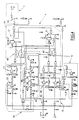
- each sensor passes through filtering means designated by the general reference 45 for the sensor 2 and means for comparison to hysteresis of the filtered signal at a predetermined threshold, designated by the general reference 46 for sensor 2, in order to deliver a signal S2 indicative of the result of the comparison to constitute the order of lighting on / off of the vehicle according to the level of natural light.
- circuit branch corresponding to the sensor 3 being identical, we will not describe it in more detail later and we will simply note that it delivers a signal S3 equivalent to the signal S2.
- the artificial light processing means 9 include them two portions each associated with one of the sensors.
- these second artificial light analysis means include for each sensor, such as for example for sensor 2, means for decoupling the DC signal component from the output signal of each sensor, these means being designated by the general reference 47 in this figure 4 for the sensor 2, and means for shaping the output signal of these decoupling means, designated by the general reference 48 in this figure, these signal shaping means comprising clipping means 49, filter means 50 and signal amplification means 51.
- the third dark sky analysis means designated by the reference general 10 include differential amplification means receiving as input the sensor output signals, these means differential amplification being designated by the general reference 52 on this FIG. 4, and means for comparing the output of these amplification means differential at a predetermined threshold, to supply or not the information of time delay depending on the result of this comparison.
- the processing logic 11 for its part comprises the memories M1 and M2 described previously and the timers T1 and T2 described previously.
- each storage means M1 and M2 comprises two RS flip-flops each consisting of two NAND gates, the memory M1 being used to store from information S2 and S3, information for switching on and keeping the vehicle lights on and M2 memory being used to store the dark sky detection.
- the timers are made up of two monostables. Timer T1 is used to delay the extinction of the exit lights of a tunnel for example and the time delay T2 being used to delay the ignition lights if dark sky information is stored.
- the means for controlling the ignition of the vehicle lights designated by the general reference 7 comprise a semiconductor switching member controlled by these means, this member comprising for example a transistor designated by the general reference 54 in this FIG. 4.
- the system according to the invention has a certain number of advantages over prior art systems in the since it allows to precisely control the switching on and off of lights of a motor vehicle, by analyzing the environment in which the vehicle moves the vehicle, to avoid inadvertent control of these lights.
Landscapes
- Engineering & Computer Science (AREA)
- Mechanical Engineering (AREA)
- Lighting Device Outwards From Vehicle And Optical Signal (AREA)
Claims (14)
- System zum automatischen Einschalten der Leuchten eines Kraftfahrzeugs, umfassend mindestens zwei Lichtfühler (2,3) in der Umgebung des Fahrzeugs, die winkelmäßig gegeneinander versetzt sind, und Mittel (6) zur Verarbeitung der Ausgangssignale dieser Fühler zur Steuerung des Betriebs von Mitteln (7) zur Steuerung der Einschaltung und der Löschung der Leuchten des Fahrzeugs, dadurch gekennzeichnet, daß die Verarbeitungsmittel (6) erste Mittel (8) zur Analyse der Pegel der kontinuierlichen Signalkomponenten in den Ausgängen der Fühler (2, 3) umfassen, um den Pegel des natürlichen Lichts in der Umgebung des Fahrzeugs zu analysieren und einen Befehl zum Einschalten/Löschen der Leuchten in Abhängig von diesem zu liefern, sowie zweite Mittel (9) zur Analyse durch Erfassung des Vorhandenseins von periodischen Signalkomponenten in den Ausgängen der Fühler, um das Vorhandensein oder Nichtvorhandensein von Kunstlicht in der Umgebung des Fahrzeugs zu erfassen und entsprechend einen Befehl der Einschaltung/Löschung der Leuchten des Fahrzeugs zu liefern, und daß den ersten Analysemitteln (8) dritte Mittel (10) zur Differenzanalyse der Ausgänge der Fühler zugeordnet sind, um einen dunklen Himmel in der Umgebung des Fahrzeugs zu erfassen und eine Information zur Verzögerung der Einschaltung der Leuchten des Fahrzeugs auf einen von den ersten Analysemitteln ausgehenden Befehl hin zu liefern.
- System nach Anspruch 1, dadurch gekennzeichnet, daß der erste Fühler (2) auf den oberen Teil des Fahrzeugs zu und der zweite (3) auf seinen vorderen oder hinteren Teil zu gerichtet ist.
- System nach Anspruch 2, dadurch gekennzeichnet, daß die Fühler (2, 3) über dem Armaturenbrett des Fahrzeugs angeordnet sind.
- System nach Anspruch 3, dadurch gekennzeichnet, daß die Fühler (2, 3) dem Innenrückspiegel des Fahrzeugs zugeordnet sind.
- System nach einem der Ansprüche 2 bis 4, dadurch gekennzeichnet, daß der erste Fühler (2), der auf den oberen Teil des Fahrzeugs zu gerichtet ist, eine vertikale Achse aufweist und der zweite (3), der bezüglich des Fahrzeugs nach vorne oder hinten gerichtet ist, eine Achse aufweist, die mit dieser einen Winkel zwischen etwa 45° und etwa 90° bildet.
- System nach einem der vorhergehenden Ansprüche, dadurch gekennzeichnet, daß die Fühler (2, 3) Photodioden umfassen.
- System nach einem der vorhergehenden Ansprüche, dadurch gekennzeichnet, daß die ersten Mittel (8) zur Analyse des Pegels des natürlichen Lichts für jeden Fühler Filtermittel (45) und Mittel(46) mit Hysterese zum Vergleichen des gefilterten Signals mit einer vorbestimmten Schwelle aufweisen, um ein das Ergebnis des Vergleichs angebendes Signal zu liefern, wobei dieses Signal den Befehl zum Einschalten/Löschen der Leuchten des Fahrzeugs in Abhängigkeit von dem Pegel des natürlichen Lichts bildet.
- System nach Anspruch 7, dadurch gekennzeichnet, daß die ersten Analysemittel (8) Mittel (11) zum Vergleichen der von den beiden Fühlern ausgehenden Einschalt/Lösch-Befehle umfassen, um die Einschaltung/Löschung der Leuchten des Fahrzeugs nur zuzulassen, wenn die beiden Befehle identisch sind.
- System nach einem der vorhergehenden Ansprüche, dadurch gekennzeichnet, daß die zweiten Mittel (9) zur Analyse des künstlichen Lichts für jeden Fühler Mittel (47) zur Entkopplung der kontinuierlichen Signalkomponente in dem Ausgangssignal jedes Fühlers und Mittel (48) zur Formung des Ausgangssignals dieser Entkopplungsmittel umfassen.
- System nach Anspruch 9, dadurch gekennzeichnet, daß die Formungsmittel (48) Mittel (49) zur Spitzenbegrenzung, Mittel (50) zur Filterung und Mittel (51) zur Verstärkung des Signals umfassen.
- System nach einem der vorhergehenden Ansprüche, dadurch gekennzeichnet, daß die dritten Mittel (10) zur Analyse des dunklen Himmels Differenzverstärkungsmittel (52) umfassen, die am Eingang die Ausgangssignale der Fühler empfangen, und Mittel (53) zum Vergleichen des Ausgangs dieser Differenzverstärkungsmittel mit einer vorbestimmten Schwelle umfassen, um die Verzögerungsinformation in Abhängigkeit von dem Ergebnis dieses Vergleichs zu liefern oder nicht zu liefern.
- System nach einem der vorhergehenden Ansprüche, dadurch gekennzeichnet, daß die Verarbeitungsmittel Mittel (M1, M2) zum Speichern des Befehls zur Einschaltung der Leuchten des Fahrzeugs und der Verzögerungsinformation umfassen, die von den ersten bzw. den dritten Analysemitteln ausgehen.
- System nach einem der vorhergehenden Ansprüche, dadurch gekennzeichnet, daß die Verarbeitungsmittel Mittel (T2) zur Verzögerung der Löschung der Leuchten des Fahrzeugs ausgehend von den von den ersten und zweiten Analysemitteln ausgehenden Befehlen umfassen.
- System nach einem der vorhergehenden Ansprüche, dadurch gekennzeichnet, daß die Mittel (7) zur Steuerung der Einschaltung und der Löschung der Leuchten des Fahrzeugs ein Halbleiter-Schaltorgan (54) umfassen, das durch die Verarbeitungsmittel gesteuert wird.
Applications Claiming Priority (2)
| Application Number | Priority Date | Filing Date | Title |
|---|---|---|---|
| FR9712911A FR2769557B1 (fr) | 1997-10-15 | 1997-10-15 | Systeme d'allumage automatique des feux d'un vehicule automobile |
| FR9712911 | 1997-10-15 |
Publications (2)
| Publication Number | Publication Date |
|---|---|
| EP0911216A1 EP0911216A1 (de) | 1999-04-28 |
| EP0911216B1 true EP0911216B1 (de) | 2003-04-02 |
Family
ID=9512265
Family Applications (1)
| Application Number | Title | Priority Date | Filing Date |
|---|---|---|---|
| EP98402554A Expired - Lifetime EP0911216B1 (de) | 1997-10-15 | 1998-10-14 | Automatische Steuerung des Einschaltens der Kfz-Leuchten |
Country Status (4)
| Country | Link |
|---|---|
| EP (1) | EP0911216B1 (de) |
| DE (1) | DE69812836T2 (de) |
| ES (1) | ES2195292T3 (de) |
| FR (1) | FR2769557B1 (de) |
Cited By (1)
| Publication number | Priority date | Publication date | Assignee | Title |
|---|---|---|---|---|
| WO2024227664A1 (de) * | 2023-05-03 | 2024-11-07 | Audi Ag | Kraftfahrzeug und verfahren zum betrieb eines kraftfahrzeugs |
Families Citing this family (6)
| Publication number | Priority date | Publication date | Assignee | Title |
|---|---|---|---|---|
| AU1125701A (en) * | 1999-11-17 | 2001-05-30 | Hts High Technology Systems Ag | Control of lighting installations |
| DE10014549A1 (de) * | 2000-03-23 | 2001-09-27 | Bosch Gmbh Robert | Einrichtung zur automatischen Schaltung von Beleuchtungseinrichtungen bei Fahrzeugen |
| DE10241895A1 (de) * | 2002-09-10 | 2004-03-11 | Robert Bosch Gmbh | Vorrichtung und Verfahren zum automatischen Steuern von Beleuchtungseinrichtungen |
| DE102005008850B4 (de) | 2005-02-26 | 2022-10-06 | Kostal Automobil Elektrik Gmbh & Co. Kg | Vorrichtung zum automatischen Ein- und Ausschalten von Beleuchtungseinrichtungen eines Kraftfahrzeugs |
| DE102007006500A1 (de) * | 2007-02-09 | 2008-08-14 | Bayerische Motoren Werke Aktiengesellschaft | Fahrzeugleuchtensteuerungssystem |
| CN117022099A (zh) * | 2023-08-07 | 2023-11-10 | 一汽解放汽车有限公司 | 近光灯控制方法、装置、计算机设备、存储介质和产品 |
Family Cites Families (4)
| Publication number | Priority date | Publication date | Assignee | Title |
|---|---|---|---|---|
| US2944188A (en) * | 1958-04-10 | 1960-07-05 | Gen Motors Corp | Automatic light controlled headlamp means |
| DE2527877C3 (de) * | 1975-06-23 | 1978-03-23 | Krone Gmbh, 1000 Berlin | Steuereinrichtung zum selbsttätigen Schalten von Leuchten |
| GB9424702D0 (en) * | 1994-12-07 | 1995-02-01 | Stewart Alexander | Control of a light source associated with a vehicle |
| DE19523262A1 (de) * | 1995-06-27 | 1997-01-02 | Bosch Gmbh Robert | Einrichtung zur automatischen Schaltung von Beleuchtungseinrichtungen bei Fahrzeugen |
-
1997
- 1997-10-15 FR FR9712911A patent/FR2769557B1/fr not_active Expired - Fee Related
-
1998
- 1998-10-14 ES ES98402554T patent/ES2195292T3/es not_active Expired - Lifetime
- 1998-10-14 EP EP98402554A patent/EP0911216B1/de not_active Expired - Lifetime
- 1998-10-14 DE DE69812836T patent/DE69812836T2/de not_active Expired - Lifetime
Cited By (1)
| Publication number | Priority date | Publication date | Assignee | Title |
|---|---|---|---|---|
| WO2024227664A1 (de) * | 2023-05-03 | 2024-11-07 | Audi Ag | Kraftfahrzeug und verfahren zum betrieb eines kraftfahrzeugs |
Also Published As
| Publication number | Publication date |
|---|---|
| DE69812836D1 (de) | 2003-05-08 |
| ES2195292T3 (es) | 2003-12-01 |
| EP0911216A1 (de) | 1999-04-28 |
| FR2769557A1 (fr) | 1999-04-16 |
| FR2769557B1 (fr) | 1999-12-31 |
| DE69812836T2 (de) | 2003-11-06 |
Similar Documents
| Publication | Publication Date | Title |
|---|---|---|
| EP0186571B1 (de) | Automatische Scheinwerfereinstellung zur Korrektur des Einflusses der Veränderung der Neigung des Lichtbündels relativ zur Strasse | |
| FR2559282A1 (fr) | Appareil pour la commande automatique de lanternes pour un vehicule | |
| FR2736016A1 (fr) | Installation de commande automatique des installations d'eclairage d'un vehicule automobile | |
| EP0911216B1 (de) | Automatische Steuerung des Einschaltens der Kfz-Leuchten | |
| CH657182A5 (fr) | Dispositif automatique de commande d'un dispositif de protection solaire, notamment un store. | |
| FR2723448A1 (fr) | Dispositif de detection d'eau ou analogue sur une glace de vehicule automobile | |
| EP0455524A1 (de) | Beleuchtungs- und Anzeigesystem für Fahrzeuge | |
| FR2528777A1 (fr) | Dispositif pour regler automatiquement la frequence d'activation d'un essuie-glace de vehicule automobile | |
| EP2023125A1 (de) | Verfahren zur Erfassung eines Wasserschauers hinter einem Kraftfahrzeug | |
| FR2845165A1 (fr) | Detecteur d'obstacle pour ouvrant de vehicule automobile | |
| FR2513198A1 (fr) | Retroviseur anti-eblouissant | |
| FR3048124A1 (fr) | Circuit de detection d'impulsions lumineuses | |
| EP1422663B1 (de) | Verfahren und Anordnung zur Bestimmung der Sichtweite eines Fahrzeuglenkers | |
| EP0570291A1 (de) | Automatische Scheinwerfereinstellung zur Korrektur des Einflusses von Lageveränderungen eines Fahrzeugs relativ zur Stra e | |
| FR2845113A1 (fr) | Detecteur d'obstacle direct et indirect pour ouvrant de vehicule automobile | |
| EP1006021B1 (de) | Verfahren und Einrichtung zur automatischen Steuerung von Kfz-Leuchten | |
| WO2022122853A1 (fr) | Procédé de contrôle d'un système d'éclairage intérieur d'un véhicule automobile | |
| FR3094300A1 (fr) | Véhicule comprenant un ensemble déflecteur d’air et un dispositif lumineux | |
| FR2875453A1 (fr) | Dispositif d'eclairage pour vehicule automobile | |
| FR2970928A1 (fr) | Procede et dispositif de controle d'un mecanisme d'essuie vitre | |
| FR2560353A1 (fr) | Dispositif d'eclairage d'un vehicule automobile et bloc optique en comportant application | |
| JPH0640286A (ja) | 自動点消灯制御装置 | |
| EP0600798B1 (de) | Automatische Scheinwerfereinstellung zur Korrektur des Einflusses der Neigungsveränderung einer Fahrzeugkarosserie auf die Richtung des Lichtbündels relativ zur Strasse | |
| KR0167952B1 (ko) | 차량의 룸미러 자동 회전장치 | |
| FR2939194A1 (fr) | Capteur de luminosite, notamment pour vehicule automobile |
Legal Events
| Date | Code | Title | Description |
|---|---|---|---|
| PUAI | Public reference made under article 153(3) epc to a published international application that has entered the european phase |
Free format text: ORIGINAL CODE: 0009012 |
|
| AK | Designated contracting states |
Kind code of ref document: A1 Designated state(s): CH DE ES GB IT LI PT SE |
|
| AX | Request for extension of the european patent |
Free format text: AL;LT;LV;MK;RO;SI |
|
| 17P | Request for examination filed |
Effective date: 19990920 |
|
| AKX | Designation fees paid |
Free format text: CH DE ES GB IT LI PT SE |
|
| 17Q | First examination report despatched |
Effective date: 20010905 |
|
| GRAH | Despatch of communication of intention to grant a patent |
Free format text: ORIGINAL CODE: EPIDOS IGRA |
|
| GRAH | Despatch of communication of intention to grant a patent |
Free format text: ORIGINAL CODE: EPIDOS IGRA |
|
| GRAA | (expected) grant |
Free format text: ORIGINAL CODE: 0009210 |
|
| AK | Designated contracting states |
Designated state(s): CH DE ES GB IT LI PT SE |
|
| REG | Reference to a national code |
Ref country code: GB Ref legal event code: FG4D Free format text: NOT ENGLISH |
|
| REG | Reference to a national code |
Ref country code: CH Ref legal event code: EP |
|
| REF | Corresponds to: |
Ref document number: 69812836 Country of ref document: DE Date of ref document: 20030508 Kind code of ref document: P |
|
| GBT | Gb: translation of ep patent filed (gb section 77(6)(a)/1977) |
Effective date: 20030514 |
|
| PG25 | Lapsed in a contracting state [announced via postgrant information from national office to epo] |
Ref country code: SE Free format text: LAPSE BECAUSE OF FAILURE TO SUBMIT A TRANSLATION OF THE DESCRIPTION OR TO PAY THE FEE WITHIN THE PRESCRIBED TIME-LIMIT Effective date: 20030702 Ref country code: PT Free format text: LAPSE BECAUSE OF FAILURE TO SUBMIT A TRANSLATION OF THE DESCRIPTION OR TO PAY THE FEE WITHIN THE PRESCRIBED TIME-LIMIT Effective date: 20030702 |
|
| PG25 | Lapsed in a contracting state [announced via postgrant information from national office to epo] |
Ref country code: LI Free format text: LAPSE BECAUSE OF NON-PAYMENT OF DUE FEES Effective date: 20031031 Ref country code: CH Free format text: LAPSE BECAUSE OF NON-PAYMENT OF DUE FEES Effective date: 20031031 |
|
| PLBE | No opposition filed within time limit |
Free format text: ORIGINAL CODE: 0009261 |
|
| STAA | Information on the status of an ep patent application or granted ep patent |
Free format text: STATUS: NO OPPOSITION FILED WITHIN TIME LIMIT |
|
| 26N | No opposition filed |
Effective date: 20040105 |
|
| REG | Reference to a national code |
Ref country code: CH Ref legal event code: PL |
|
| REG | Reference to a national code |
Ref country code: GB Ref legal event code: 746 Effective date: 20070118 |
|
| PGFP | Annual fee paid to national office [announced via postgrant information from national office to epo] |
Ref country code: ES Payment date: 20081007 Year of fee payment: 11 |
|
| PGFP | Annual fee paid to national office [announced via postgrant information from national office to epo] |
Ref country code: IT Payment date: 20081016 Year of fee payment: 11 |
|
| REG | Reference to a national code |
Ref country code: ES Ref legal event code: FD2A Effective date: 20110310 |
|
| PG25 | Lapsed in a contracting state [announced via postgrant information from national office to epo] |
Ref country code: IT Free format text: LAPSE BECAUSE OF NON-PAYMENT OF DUE FEES Effective date: 20091014 |
|
| PG25 | Lapsed in a contracting state [announced via postgrant information from national office to epo] |
Ref country code: ES Free format text: LAPSE BECAUSE OF NON-PAYMENT OF DUE FEES Effective date: 20110309 |
|
| PG25 | Lapsed in a contracting state [announced via postgrant information from national office to epo] |
Ref country code: ES Free format text: LAPSE BECAUSE OF NON-PAYMENT OF DUE FEES Effective date: 20091015 |
|
| PGFP | Annual fee paid to national office [announced via postgrant information from national office to epo] |
Ref country code: GB Payment date: 20120924 Year of fee payment: 15 |
|
| PGFP | Annual fee paid to national office [announced via postgrant information from national office to epo] |
Ref country code: DE Payment date: 20120924 Year of fee payment: 15 |
|
| GBPC | Gb: european patent ceased through non-payment of renewal fee |
Effective date: 20131014 |
|
| REG | Reference to a national code |
Ref country code: DE Ref legal event code: R119 Ref document number: 69812836 Country of ref document: DE Effective date: 20140501 |
|
| PG25 | Lapsed in a contracting state [announced via postgrant information from national office to epo] |
Ref country code: GB Free format text: LAPSE BECAUSE OF NON-PAYMENT OF DUE FEES Effective date: 20131014 |
|
| PG25 | Lapsed in a contracting state [announced via postgrant information from national office to epo] |
Ref country code: DE Free format text: LAPSE BECAUSE OF NON-PAYMENT OF DUE FEES Effective date: 20140501 |