EP0911830A2 - Wiedergabegerät, Aufzeichnungsgerät und Aufzeichnungsmedium - Google Patents
Wiedergabegerät, Aufzeichnungsgerät und Aufzeichnungsmedium Download PDFInfo
- Publication number
- EP0911830A2 EP0911830A2 EP98119728A EP98119728A EP0911830A2 EP 0911830 A2 EP0911830 A2 EP 0911830A2 EP 98119728 A EP98119728 A EP 98119728A EP 98119728 A EP98119728 A EP 98119728A EP 0911830 A2 EP0911830 A2 EP 0911830A2
- Authority
- EP
- European Patent Office
- Prior art keywords
- data
- auxiliary
- sector
- main
- area
- Prior art date
- Legal status (The legal status is an assumption and is not a legal conclusion. Google has not performed a legal analysis and makes no representation as to the accuracy of the status listed.)
- Withdrawn
Links
Images

















Classifications
-
- G—PHYSICS
- G10—MUSICAL INSTRUMENTS; ACOUSTICS
- G10H—ELECTROPHONIC MUSICAL INSTRUMENTS; INSTRUMENTS IN WHICH THE TONES ARE GENERATED BY ELECTROMECHANICAL MEANS OR ELECTRONIC GENERATORS, OR IN WHICH THE TONES ARE SYNTHESISED FROM A DATA STORE
- G10H1/00—Details of electrophonic musical instruments
- G10H1/36—Accompaniment arrangements
- G10H1/361—Recording/reproducing of accompaniment for use with an external source, e.g. karaoke systems
- G10H1/368—Recording/reproducing of accompaniment for use with an external source, e.g. karaoke systems displaying animated or moving pictures synchronized with the music or audio part
-
- G—PHYSICS
- G10—MUSICAL INSTRUMENTS; ACOUSTICS
- G10H—ELECTROPHONIC MUSICAL INSTRUMENTS; INSTRUMENTS IN WHICH THE TONES ARE GENERATED BY ELECTROMECHANICAL MEANS OR ELECTRONIC GENERATORS, OR IN WHICH THE TONES ARE SYNTHESISED FROM A DATA STORE
- G10H1/00—Details of electrophonic musical instruments
- G10H1/36—Accompaniment arrangements
- G10H1/361—Recording/reproducing of accompaniment for use with an external source, e.g. karaoke systems
- G10H1/363—Recording/reproducing of accompaniment for use with an external source, e.g. karaoke systems using optical disks, e.g. CD, CD-ROM, to store accompaniment information in digital form
-
- G—PHYSICS
- G11—INFORMATION STORAGE
- G11B—INFORMATION STORAGE BASED ON RELATIVE MOVEMENT BETWEEN RECORD CARRIER AND TRANSDUCER
- G11B20/00—Signal processing not specific to the method of recording or reproducing; Circuits therefor
- G11B20/10—Digital recording or reproducing
- G11B20/10527—Audio or video recording; Data buffering arrangements
-
- G—PHYSICS
- G11—INFORMATION STORAGE
- G11B—INFORMATION STORAGE BASED ON RELATIVE MOVEMENT BETWEEN RECORD CARRIER AND TRANSDUCER
- G11B20/00—Signal processing not specific to the method of recording or reproducing; Circuits therefor
- G11B20/10—Digital recording or reproducing
- G11B20/12—Formatting, e.g. arrangement of data block or words on the record carriers
- G11B20/1217—Formatting, e.g. arrangement of data block or words on the record carriers on discs
- G11B20/1254—Formatting, e.g. arrangement of data block or words on the record carriers on discs for mixed data, i.e. continuous and discontinuous data
-
- G—PHYSICS
- G11—INFORMATION STORAGE
- G11B—INFORMATION STORAGE BASED ON RELATIVE MOVEMENT BETWEEN RECORD CARRIER AND TRANSDUCER
- G11B27/00—Editing; Indexing; Addressing; Timing or synchronising; Monitoring; Measuring tape travel
- G11B27/02—Editing, e.g. varying the order of information signals recorded on, or reproduced from, record carriers
- G11B27/031—Electronic editing of digitised analogue information signals, e.g. audio or video signals
- G11B27/034—Electronic editing of digitised analogue information signals, e.g. audio or video signals on discs
-
- G—PHYSICS
- G11—INFORMATION STORAGE
- G11B—INFORMATION STORAGE BASED ON RELATIVE MOVEMENT BETWEEN RECORD CARRIER AND TRANSDUCER
- G11B27/00—Editing; Indexing; Addressing; Timing or synchronising; Monitoring; Measuring tape travel
- G11B27/02—Editing, e.g. varying the order of information signals recorded on, or reproduced from, record carriers
- G11B27/031—Electronic editing of digitised analogue information signals, e.g. audio or video signals
- G11B27/036—Insert-editing
-
- G—PHYSICS
- G11—INFORMATION STORAGE
- G11B—INFORMATION STORAGE BASED ON RELATIVE MOVEMENT BETWEEN RECORD CARRIER AND TRANSDUCER
- G11B27/00—Editing; Indexing; Addressing; Timing or synchronising; Monitoring; Measuring tape travel
- G11B27/10—Indexing; Addressing; Timing or synchronising; Measuring tape travel
- G11B27/102—Programmed access in sequence to addressed parts of tracks of operating record carriers
- G11B27/105—Programmed access in sequence to addressed parts of tracks of operating record carriers of operating discs
-
- G—PHYSICS
- G11—INFORMATION STORAGE
- G11B—INFORMATION STORAGE BASED ON RELATIVE MOVEMENT BETWEEN RECORD CARRIER AND TRANSDUCER
- G11B27/00—Editing; Indexing; Addressing; Timing or synchronising; Monitoring; Measuring tape travel
- G11B27/10—Indexing; Addressing; Timing or synchronising; Measuring tape travel
- G11B27/19—Indexing; Addressing; Timing or synchronising; Measuring tape travel by using information detectable on the record carrier
- G11B27/28—Indexing; Addressing; Timing or synchronising; Measuring tape travel by using information detectable on the record carrier by using information signals recorded by the same method as the main recording
- G11B27/32—Indexing; Addressing; Timing or synchronising; Measuring tape travel by using information detectable on the record carrier by using information signals recorded by the same method as the main recording on separate auxiliary tracks of the same or an auxiliary record carrier
- G11B27/327—Table of contents
-
- G—PHYSICS
- G11—INFORMATION STORAGE
- G11B—INFORMATION STORAGE BASED ON RELATIVE MOVEMENT BETWEEN RECORD CARRIER AND TRANSDUCER
- G11B27/00—Editing; Indexing; Addressing; Timing or synchronising; Monitoring; Measuring tape travel
- G11B27/10—Indexing; Addressing; Timing or synchronising; Measuring tape travel
- G11B27/19—Indexing; Addressing; Timing or synchronising; Measuring tape travel by using information detectable on the record carrier
- G11B27/28—Indexing; Addressing; Timing or synchronising; Measuring tape travel by using information detectable on the record carrier by using information signals recorded by the same method as the main recording
- G11B27/32—Indexing; Addressing; Timing or synchronising; Measuring tape travel by using information detectable on the record carrier by using information signals recorded by the same method as the main recording on separate auxiliary tracks of the same or an auxiliary record carrier
- G11B27/327—Table of contents
- G11B27/329—Table of contents on a disc [VTOC]
-
- G—PHYSICS
- G11—INFORMATION STORAGE
- G11B—INFORMATION STORAGE BASED ON RELATIVE MOVEMENT BETWEEN RECORD CARRIER AND TRANSDUCER
- G11B27/00—Editing; Indexing; Addressing; Timing or synchronising; Monitoring; Measuring tape travel
- G11B27/10—Indexing; Addressing; Timing or synchronising; Measuring tape travel
- G11B27/34—Indicating arrangements
-
- G—PHYSICS
- G11—INFORMATION STORAGE
- G11B—INFORMATION STORAGE BASED ON RELATIVE MOVEMENT BETWEEN RECORD CARRIER AND TRANSDUCER
- G11B7/00—Recording or reproducing by optical means, e.g. recording using a thermal beam of optical radiation by modifying optical properties or the physical structure, reproducing using an optical beam at lower power by sensing optical properties; Record carriers therefor
- G11B7/12—Heads, e.g. forming of the optical beam spot or modulation of the optical beam
- G11B7/135—Means for guiding the beam from the source to the record carrier or from the record carrier to the detector
- G11B7/1372—Lenses
- G11B7/1374—Objective lenses
-
- G—PHYSICS
- G11—INFORMATION STORAGE
- G11B—INFORMATION STORAGE BASED ON RELATIVE MOVEMENT BETWEEN RECORD CARRIER AND TRANSDUCER
- G11B7/00—Recording or reproducing by optical means, e.g. recording using a thermal beam of optical radiation by modifying optical properties or the physical structure, reproducing using an optical beam at lower power by sensing optical properties; Record carriers therefor
- G11B7/12—Heads, e.g. forming of the optical beam spot or modulation of the optical beam
- G11B7/135—Means for guiding the beam from the source to the record carrier or from the record carrier to the detector
- G11B7/1395—Beam splitters or combiners
-
- G—PHYSICS
- G11—INFORMATION STORAGE
- G11B—INFORMATION STORAGE BASED ON RELATIVE MOVEMENT BETWEEN RECORD CARRIER AND TRANSDUCER
- G11B7/00—Recording or reproducing by optical means, e.g. recording using a thermal beam of optical radiation by modifying optical properties or the physical structure, reproducing using an optical beam at lower power by sensing optical properties; Record carriers therefor
- G11B7/24—Record carriers characterised by shape, structure or physical properties, or by the selection of the material
- G11B7/24094—Indication parts or information parts for identification
-
- G—PHYSICS
- G10—MUSICAL INSTRUMENTS; ACOUSTICS
- G10H—ELECTROPHONIC MUSICAL INSTRUMENTS; INSTRUMENTS IN WHICH THE TONES ARE GENERATED BY ELECTROMECHANICAL MEANS OR ELECTRONIC GENERATORS, OR IN WHICH THE TONES ARE SYNTHESISED FROM A DATA STORE
- G10H2220/00—Input/output interfacing specifically adapted for electrophonic musical tools or instruments
- G10H2220/005—Non-interactive screen display of musical or status data
- G10H2220/011—Lyrics displays, e.g. for karaoke applications
-
- G—PHYSICS
- G11—INFORMATION STORAGE
- G11B—INFORMATION STORAGE BASED ON RELATIVE MOVEMENT BETWEEN RECORD CARRIER AND TRANSDUCER
- G11B11/00—Recording on or reproducing from the same record carrier wherein for these two operations the methods are covered by different main groups of groups G11B3/00 - G11B7/00 or by different subgroups of group G11B9/00; Record carriers therefor
- G11B11/10—Recording on or reproducing from the same record carrier wherein for these two operations the methods are covered by different main groups of groups G11B3/00 - G11B7/00 or by different subgroups of group G11B9/00; Record carriers therefor using recording by magnetic means or other means for magnetisation or demagnetisation of a record carrier, e.g. light induced spin magnetisation; Demagnetisation by thermal or stress means in the presence or not of an orienting magnetic field
- G11B11/105—Recording on or reproducing from the same record carrier wherein for these two operations the methods are covered by different main groups of groups G11B3/00 - G11B7/00 or by different subgroups of group G11B9/00; Record carriers therefor using recording by magnetic means or other means for magnetisation or demagnetisation of a record carrier, e.g. light induced spin magnetisation; Demagnetisation by thermal or stress means in the presence or not of an orienting magnetic field using a beam of light or a magnetic field for recording by change of magnetisation and a beam of light for reproducing, i.e. magneto-optical, e.g. light-induced thermomagnetic recording, spin magnetisation recording, Kerr or Faraday effect reproducing
- G11B11/10595—Control of operating function
-
- G—PHYSICS
- G11—INFORMATION STORAGE
- G11B—INFORMATION STORAGE BASED ON RELATIVE MOVEMENT BETWEEN RECORD CARRIER AND TRANSDUCER
- G11B20/00—Signal processing not specific to the method of recording or reproducing; Circuits therefor
- G11B20/10—Digital recording or reproducing
- G11B20/12—Formatting, e.g. arrangement of data block or words on the record carriers
- G11B20/1217—Formatting, e.g. arrangement of data block or words on the record carriers on discs
- G11B2020/1218—Formatting, e.g. arrangement of data block or words on the record carriers on discs wherein the formatting concerns a specific area of the disc
- G11B2020/1242—Formatting, e.g. arrangement of data block or words on the record carriers on discs wherein the formatting concerns a specific area of the disc the area forming one or more zones, wherein each zone is shaped like an annulus or a circular sector
- G11B2020/1245—CLV zone, in which a constant linear velocity is used
-
- G—PHYSICS
- G11—INFORMATION STORAGE
- G11B—INFORMATION STORAGE BASED ON RELATIVE MOVEMENT BETWEEN RECORD CARRIER AND TRANSDUCER
- G11B20/00—Signal processing not specific to the method of recording or reproducing; Circuits therefor
- G11B20/10—Digital recording or reproducing
- G11B20/14—Digital recording or reproducing using self-clocking codes
- G11B20/1403—Digital recording or reproducing using self-clocking codes characterised by the use of two levels
- G11B20/1423—Code representation depending on subsequent bits, e.g. delay modulation, double density code, Miller code
- G11B20/1426—Code representation depending on subsequent bits, e.g. delay modulation, double density code, Miller code conversion to or from block codes or representations thereof
- G11B2020/1461—8 to 14 modulation, e.g. the EFM code used on CDs or mini-discs
-
- G—PHYSICS
- G11—INFORMATION STORAGE
- G11B—INFORMATION STORAGE BASED ON RELATIVE MOVEMENT BETWEEN RECORD CARRIER AND TRANSDUCER
- G11B2220/00—Record carriers by type
- G11B2220/20—Disc-shaped record carriers
- G11B2220/25—Disc-shaped record carriers characterised in that the disc is based on a specific recording technology
- G11B2220/2525—Magneto-optical [MO] discs
- G11B2220/2529—Mini-discs
-
- G—PHYSICS
- G11—INFORMATION STORAGE
- G11B—INFORMATION STORAGE BASED ON RELATIVE MOVEMENT BETWEEN RECORD CARRIER AND TRANSDUCER
- G11B23/00—Record carriers not specific to the method of recording or reproducing; Accessories, e.g. containers, specially adapted for co-operation with the recording or reproducing apparatus ; Intermediate mediums; Apparatus or processes specially adapted for their manufacture
- G11B23/30—Record carriers not specific to the method of recording or reproducing; Accessories, e.g. containers, specially adapted for co-operation with the recording or reproducing apparatus ; Intermediate mediums; Apparatus or processes specially adapted for their manufacture with provision for auxiliary signals
- G11B23/36—Signals on record carriers or on containers and recorded by the same method as the main recording
-
- G—PHYSICS
- G11—INFORMATION STORAGE
- G11B—INFORMATION STORAGE BASED ON RELATIVE MOVEMENT BETWEEN RECORD CARRIER AND TRANSDUCER
- G11B33/00—Constructional parts, details or accessories not provided for in the other groups of this subclass
- G11B33/10—Indicating arrangements; Warning arrangements
Definitions
- the present invention generally relates to a recording medium capable of recording main data such as audio data for example and auxiliary data such as character information and image information for example, a recording apparatus compatible with this recording medium, and a reproducing apparatus compatible with this recording medium.
- a recording and/or reproducing apparatus that uses a recording medium such as a magneto-optical disc for digitally recording an audio signal or a magnetic tape is known as a recording and/or reproducing apparatus for recording and/or reproducing music data and so on.
- a recording and/or reproducing system that uses magneto-optical disc known as a Mini Disc (trademark) allows its user not only to record and reproduce an audio signal such as of music as a program but also to record as character information a disc name, which is a disc title name, and a track name, which is a music title, of each program of recorded music.
- a disc name which is a disc title name
- a track name which is a music title
- program used herein denotes the unit of audio data such as music as the main data to be recorded on a disc.
- program denotes the unit of audio data such as music as the main data to be recorded on a disc.
- one piece of music of audio data provides one program.
- track is also used hereafter to denote the above-mentioned program.
- the information recorded as a disc name and a track name is not so large in size; namely, the information is only sufficient in size to record the number of characters constituting several titles such as mentioned above.
- control information U-TOC User Table of Contents
- character information for each program can be recorded and its recordable size is not so large. For example, a comparatively large size of character information such as a lyrics text of a song recorded as a program cannot be recorded in a U-TOC.
- the character information in a U-TOC is only related to a program as a whole; namely, it is not related to a particular reproducing position in a piece of music for example as a program. Therefore, a character information display timing cannot be set, according to a play position, to music to be reproduced. For example, even if a comparatively large size of character information equivalent to a lyrics text of music can be recorded, the lyrics text cannot be displayed in synchronization with the progress of the play. For example, displaying a lyrics text in synchronization with a vocal or for lyrics text guiding in karaoke playing.
- the data unit called a cluster provides the basic unit of a recording operation.
- This cluster has an area of 32 sectors in which audio data is recorded as a program and an area in which one sector of auxiliary data is recorded. Therefore, storing the character information such as a lyrics text corresponding to the audio data stored in a cluster onto the auxiliary data area in each cluster can record a comparatively large size of lyrics text information and output the recorded information for display in synchronization with the play of music.
- auxiliary data alone cannot be recorded. Therefore, because additional recording of auxiliary data alone is disabled, if an attempt is made to additionally record character information providing a lyrics text onto auxiliary data for a recorded piece of music to be rewritten, all of the audio data, which is the main data, and the auxiliary data, which is character information, must be recorded again. This holds true with modifying character information. Hence, additional writing or modification of character information or adjustment of display timing is not necessarily impossible but is burdensome and takes time.
- the audio data which is the main data, must be reproduced in a predetermined amount and the reproduced audio data must be stored in memory. Then, the stored audio data must be read on a cluster basis and character information must be added to the auxiliary data portion to be recorded onto disc again.
- the recording and/or reproducing apparatus records a program that provides main data and a data file that provides auxiliary data such as characters and images, outputs the data file as lyrics text information for example in synchronization with the reproduction of the main program or in synchronization with a fine timing such as of a position inside music for example, and controls the data file independently of the main program for more versatile output forms.
- the added value of the recording and/or reproducing apparatus according to the invention is still enhanced by enabling the recording, editing, and reproducing of the data file alone as auxiliary data.
- a reproducing apparatus for reproducing a recording medium having main data area for recording a main program composed of main data, an auxiliary data area for recording an auxiliary program composed of auxiliary data corresponding to the main program composed of the main data in the main data area, a first control area for controlling at least a recording position of the main program composed of the main data in the main data area, and a second control area for controlling at least a recording position of the auxiliary program composed of the auxiliary data in the auxiliary data area and timing information for reproducing the auxiliary program in synchronization with the main program composed of the main data in the main data area
- the reproducing apparatus comprising: a reproducing module for reproducing the first control area, the second control area, the auxiliary data area, and the main data area sequentially; a memory module for storing the auxiliary program composed of the auxiliary data reproduced by the reproducing module from the auxiliary data area; a memory control module for reading from the memory module the auxiliary program composed of the auxiliary data
- a recording apparatus for recording auxiliary data in a manner related to main data onto a recording medium having main data area for recording a main program composed of the main data, an auxiliary data area for recording an auxiliary program composed of the auxiliary data corresponding to the main program composed of the main data in the main data area, a first control area for controlling at least a recording position of the main program composed of the main data in the main data area, and a second control area for controlling at least a recording position of the auxiliary program composed of the auxiliary data in the auxiliary data area and timing information for reproducing the auxiliary program in synchronization with the main program composed of the main data in the main data area
- the recording apparatus comprising: a recording module for recording the auxiliary program composed of the auxiliary data corresponding to the main program onto the auxiliary data area; an operating module for relating the auxiliary program recorded by the recording module to the main program recorded in the main data area; and an updating module for updating, based on the recording position of the auxiliary program recorded in
- a recording medium having a main data area for recording at least one main program composed of main data, an auxiliary data area for recording an auxiliary program composed of auxiliary data corresponding to the main program composed of the main data, a first control area for controlling at least a recording position of the main program composed of the main data in the main data area, and a second control area for controlling at least a recording position of the auxiliary program composed of the auxiliary data in the auxiliary data area and timing information for reproducing the auxiliary program in synchronization with the main program composed of the main data recorded in the main data area.
- a magneto-optical disc (or a Mini Disc) is used by way of example of a recording medium and a Mini Disc recording and/or reproducing apparatus is used by way of example of a recording apparatus and a reproducing apparatus.
- FIG. 1 is a block diagram illustrating an internal constitution of a Mini Disc recording and/or reproducing apparatus 1 practiced as one preferred embodiment of the invention.
- a magneto-optical disc (a Mini Disc) 90 on which audio data is recorded is rotatably driven by a spindle motor 2.
- a laser beam is radiated from an optical head 3 onto the magneto-optical disc 90 at the time of a data recording and/or reproducing operation.
- the optical head 3 performs, at recording, a high-level laser output operation to heat a recording track to the Curie temperature and, at reproduction, a comparatively low laser output operation to detect data from the reflected laser beam by the magnetic Kerr effect.
- the optical head 3 has a laser diode as a laser output means, an optical system composed of a polarized beam splitter and an objective lens 3a, and a detector for detecting a reflected laser beam.
- the objective lens 3a is displaceably held by a two-axis feed mechanism in radial and axial directions relative to the disc 90.
- a magnetic head 6a is arranged at a position opposed to the optical head 3 with the disc 90 located in between.
- the magnetic head 6a field-modulates modulated data supplied from an EFM (Eight-to-Fourteen Modulation)/ACIRC (Advanced Cross Interleave Reed Solomon Coding) encoder/decoder 8 and applies resultant data onto the magneto-optical disc 90.
- EFM Eight-to-Fourteen Modulation
- ACIRC Advanced Cross Interleave Reed Solomon Coding
- the entire optical head 3 and the magnetic head 6a are movable by a sled-feed mechanism 5 in the radial direction relative to the disc 90.
- Information read from the disc 90 by the optical head 3 in a reproducing operation is supplied to an RF amplifier 7. From the supplied information, the RF amplifier 7 extracts by computation a reproduced RF signal, a tracking error signal TE, a focus error signal FE, and groove information GFM.
- the groove information GMF denotes absolute positional information recorded on the disc 90 beforehand as a pre-groove (Wobbling Groove).
- the extracted reproduced RF signal is supplied to the EFM/ACIRC encoder/decoder 8.
- the tracking error signal TE and the focus error signal FE are supplied to a servo circuit 9.
- the groove information GFM is supplied to an address decoder 10.
- the servo circuit 9 Based on the supplied tracking error signal TE, the focus error signal FE, a track jump command and an access command issued from a system controller 11 constituted by a microcomputer, and revolution detect information of the spindle motor 2, the servo circuit 9 generates various servo drive signals to control the two-axis feed mechanism 4 and the sled-feed mechanism 5, thereby performing focus control and tracking control and controlling the spindle motor 2 to a constant linear velocity (CLV).
- CLV constant linear velocity
- the address decoder 10 decodes the supplied groove information GFM to extract address information.
- the extracted address information is supplied to the system controller 11 to be used for various control operations.
- EFM/ACIRC encoder/decoder 8 performs EFM (Eight-to-Fourteen Modulation)-demodulation and ACIRC (Advanced Cross Interleave Reed Solomon Coding)-decoding on the reproduced RF signal. At this moment, an address and auxiliary code data are also extracted to be supplied to the system controller 11.
- the audio data demodulated and decoded in the EFM/ACIRC encoder/decoder 8 is once stored by a memory controller 12 into a buffer memory 13. It should be noted that reading of data by the optical head 3 from the disc 90 and transferring of reproduced data through a path from the optical head 3 to the buffer memory 13 are performed at 1.41 Mbit/second intermittently.
- the data written to the buffer memory 13 is read in a timed relation in which the reproduced data is transferred at 0.3 Mbit/second to be supplied to an audio compression encoder/decoder 14. Then, the reproduced data undergoes such reproduced signal processing as audio decompression for audio compression to provide a digital audio signal of 44.1 KHz sampling and 16-bit quantization.
- This digital audio signal is converted by a D/A converter 15 into an analog signal to be adjusted in level and impedance by an output processor 16, being outputted from a line output terminal 17 to an external device as an analog audio signal Aout.
- the digital audio signal is also supplied to a headphone output terminal 27 as headphone output HPout to be outputted to a headphone connected to the apparatus.
- the digital audio signal as decoded by the audio compression encoder/decoder 14 is supplied to a digital interface 22 to be outputted from a digital output terminal 21 to an external device as a digital audio signal Dout.
- the digital audio signal is outputted in a transmission form based on an optical cable.
- an analog audio signal Ain which is a record signal supplied to a line input terminal 18, is converted by an A/D converter 19 into a digital signal, which is then supplied to the audio compression encoder/decoder 14 to be compressed.
- a digital audio signal Din is supplied from an external device to a digital input terminal 20
- a control code and so on are extracted from the supplied signal by the digital interface 22 and audio data carried by this signal is supplied to the audio compression encoder/decoder 14 to be compressed.
- a microphone terminal may be arranged to use a microphone input as the record signal.
- the record data compressed by the audio compression encoder/decoder 14 is once written by the memory controller 12 to the buffer memory 13 for storage.
- the stored record data is then intermittently read in data units of a predetermined size to be sent to the EFM/ACIRC encoder/decoder 8.
- the record data is ACIRC-encoded and EFM-modulated to be supplied to a magnetic head driver 6.
- the magnetic head driver 6 supplies a magnetic head drive signal to the magnetic head 6a.
- the magnetic head driver 6 has the magnetic head 6a apply N-pole or S-pole field to the magneto-optical disc 90.
- the system controller 11 supplies a control signal to the optical head 6a to output a laser beam of a high recording level.
- An operator panel 23 is a section provided for user operation and has various operator controls including keys and knobs.
- the operator controls include such controls associated with recording and/or reproducing operations as reproduction, record, pause, stop, fast forward (FF), rewind (REW), and automatic music sensor (AMS), controls associated with play modes such as normal reproduction, programmed reproduction, and shuffle reproduction, display mode controls for changing display states in a display monitor 24, controls for program editing such as track (program) split, track linkage, track erase, track name input, and disc name input, and controls necessary for auxiliary (AUX) data recording, reproducing, and operating modes to be described later in the present embodiment.
- FF fast forward
- REW rewind
- AMS automatic music sensor
- controls associated with play modes such as normal reproduction, programmed reproduction, and shuffle reproduction
- display mode controls for changing display states in a display monitor 24
- controls for program editing such as track (program) split, track linkage, track erase, track name input, and disc name input
- AUX auxiliary
- Operating information about the operation of these controls is supplied to the system controller 11, which then executes control operations according to the received operating information.
- Display operations of the display monitor 24 are controlled by the system controller 11.
- the system controller 11 sends data to be displayed when a display operation is performed to a display driver, not shown, in the display monitor 24.
- the display driver drives a display operation by a liquid crystal panel for example, thereby displaying required numerals, characters, symbols, and so on.
- the display monitor 24 displays an operation mode state of the disc being recorded and/or reproduced, a track number, recording time or reproduction time, an edit state, and so on.
- the disc 90 can record character information such an album title controlled by in accompaniment with the program, or the main data.
- the display monitor 24 displays input characters of the character information and character information read from the disc.
- the disc 90 has an audio data area which is main data and an AUX data area which is auxiliary data, these areas being discrete from each other.
- the data file as auxiliary data provides information such as characters and images. These characters and images may also be outputted to the display monitor 24.
- An AUX data file may also be recorded by the user onto the disc 90.
- input devices as an image scanner, a personal computer, and a keyboard may be required. It is possible for the information as an AUX data file to be inputted from such an input system through the interface 25.
- the system controller 11 is a microcomputer having a CPU, a program ROM, a work RAM, an interface, and so on and controls each of the operations described so far.
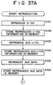
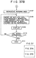
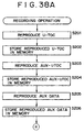
- control information namely P-TOC (Pre-mastered Table of Contents (TOC)) and U-TOC (User TOC) must be read from the disc 90.
- the system controller 11 determines the address of a recording area and the address of a reproducing area on the disc 90.
- the system controller 11 reads these pieces of control information by executing reproduction of control information recorded the innermost peripheral when the disc 90 is loaded and stores the read control information into the buffer memory 13 to reference the control information when recording, reproducing, and editing a program recorded on the disc 90.
- a U-TOC is rewritten every time program data is recorded or edited.
- the system controller 11 updates U-TOC stored in the buffer memory 13 every time such an operation is performed and rewrites the U-TOC area on the disc 90 accordingly in a predetermined timing relation.
- An AUX data file is recorded on the disc 90 separately from the program.
- AUX-TOC is formed on the disc 90.
- the system controller 11 also reads AUX-TOC at the same time U-TOC is read and stores AUX-TOC in the buffer memory 13 for reference as required.
- the system controller 11 reads the auxiliary data file in a predetermined timing relation or at the same time AUX-TOC is read as required and stores the read AUX data file into the buffer memory 13. Then, the system controller 11 has the display monitor 24 and a device externally attached through the interface 25 execute character and image output operations according to the output timing controlled by the AUX-TOC.
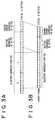
- FIGS. 2A through 2E data units called a sector and a cluster will be described below.
- clusters CLs are formed consecutively as shown in FIG. 2A, one cluster providing a minimum recording unit.
- One cluster is equivalent to two to three circles of tracks.
- One cluster CL is formed with linking area composed of four sectors SFC through SFF and a main data area composed of 32 sectors S00 through S1F as shown in FIG. 2B.
- One sector is a data unit consisting of 2352 bytes.
- the sector SFF is an auxiliary data sector, which is available for the recording of auxiliary data as shown in FIG. 2B.
- the three sectors SFC through SFE are not used for data recording.
- TOC data, audio data, and AUX data are recorded in 32 sectors of the main data area.
- a sector is further divided into sound groups, two sectors being divided into 11 sound groups (SGs) as shown in FIG. 2D.
- consecutive two sectors such as an even-number sector S00 and an odd-number sector S01 include sound groups SG00 through SG0A.
- One sound group is composed of 424 bytes, providing an audio data amount equivalent to 11. 61 msec.
- the sound group SG00 is composed of L-channel data L0 and R-channel data R0.
- the sound group SG01 is composed of L-channel data L1 and R-channel data R1.
- 212 bytes that provide an L-channel or R-channel data area is referred to as a sound frame.
- Each sector is addressed by a cluster address and a sector address.
- the address consisting of these three bytes is recorded at the head of each sector.
- Adding a sound group address consisting of four bits can represent the address of each sound group within a sector.
- notation including the sound group address allows setting of reproduction position in units of sound group.
- each sector can be represented in six bits because one cluster has 36 sectors. Therefore, the high-order two bits of each sector address can be omitted.
- each cluster can be represented in 14 bits up to the disc outermost periphery, so that the high-order two bits of each cluster address can be omitted.
- omitting the high-order two bits of each of sector address and each cluster address can represent an address specifying all of cluster, sector, and sound group in three bytes.
- each address for controlling reproduction position, reproduction timing, and so on is expressed in the above-mentioned short form.
- an absolute address or an offset address is possible for example.
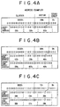
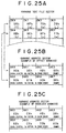
- An offset address denotes a relative address with the head position of each program such as music being defined as address 0, thereby indicating a position inside the program. An example of this offset address will be described below with reference to tables shown in FIGS 4A through 4C.
- the value of the address of cluster 32h, sector 00h, and sound group 0h of the start position of a first program is "0000000000110010000000000000" (to be more specific, 0032h, 00h, 0h) as shown in the upper portion of FIG. 4A.
- this address is indicated as "000000001100100000000000” (namely, 00h, C8h, 00h) as shown in the lower portion of FIG. 4A.
- the address of a certain position in the first program for example cluster 0032h, sector 04h, and sound group 0h
- the corresponding offset address is "00h, 00h, 40h” because cluster 0000h, sector 04h, sound group 0h may be expressed by the difference from the origin, or the start address.
- a certain position in the first program for example an address of cluster 0032h, sector 13h, sound group 9h, is "00h, C9h, 39h” in the corresponding short-form absolute address as shown in FIG. 4C and "00h, 01h, 39h” in the corresponding offset address.
- a position and so on inside a particular program can be specified by an absolute address or an offset address.
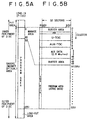
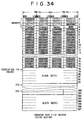
- FIG. 5A shows an area from the innermost periphery to the outermost periphery.
- the innermost periphery is a pit area formed with reproduction-only data by emboss pits, in which P-TOC is recorded.
- a magneto-optical area that provides a recording/reproduction-enabled area formed with recording track guide grooves.
- Cluster 0 through cluster 49 on the inner periphery side of the magneto-optical area provide a control area.
- An actual program such as music is recorded in a program area ranging from cluster 50 through cluster 2251.
- the program area is enclosed by a lead-out area.
- control area Details of the control area are shown in FIG. 5B, in which sectors are shown laterally while clusters are shown vertically.
- clusters 0 and 1 provide a buffer area against the pit area.
- Cluster 2 provides a power calibration area PCA for use in calibrating a laser beam output power.
- Clusters 3, 4, and 5 record U-TOC. The contents of U-TOC will be described later.
- a data format is specified in each section in one cluster to record predetermined control information.
- a sector providing such U-TOC data is recorded in clusters 3, 4, and 5 repeatedly.
- Clusters 6, 7, and 8 record AUX-TOC. Contents of AUX-TOC will be described later. A data format is specified in sector in one cluster to record predetermined control information. A sector having such AUX-TOC data is recorded in clusters 6, 7, and 8 repeatedly.
- An area from cluster 9 through cluster 46 records AUX data.
- a data file as AUX data is formed on a sector basis.
- This data file includes a picture file sector as a still picture file to be described later, a text file sector as a character information file to be described later, and a karaoke text file sector as a character information file in synchronization with program to be described later.
- the data file as the AUX data and the area enabled to record the AUX data file within the AUX data area are controlled by AUX-TOC.
- the data file recording size in the AUX data area is 2.8 MB with error correction mode 2 considered.
- a second AUX data area in, for example, the last half of the program area or an area outside the program area (for example, the lead-out portion), thereby expanding the data file recording size.
- Clusters 47, 48, and 49 provide a buffer area against the program area.
- ATRAC Adaptive Transform Acoustic Coding
- the recorded programs and recordable areas are controlled by U-TOC.
- sector FFh in each cluster in the program area can be used for recording certain information as auxiliary data as described before.
- a reproduction-only disc in which programs and so on are recorded in the pit form as reproduction-only data may be used.
- the entire disc is covered with the pit area.
- the programs recorded in the reproduction-only disc are controlled by P-TOC in generally the same manner as U-TOC. Therefore no U-TOC is formed on the reproduction-only disc.
- AUX-TOC for controlling the data file is recorded on the reproduction-only disc.
- recording and/or reproduction of a program on the disc 90 requires the system controller 11 to read control information P-TOC and U-TOC from the disc 90 beforehand to reference them as required.
- the following describes the U-TOC sector that is control information for controlling the recording and/or reproducing of a program.
- P-TOC is formed in the pit area on the inner periphery of the disc 90 as described with reference to FIGS. 5A and 5B.
- P-TOC is read-only information.
- the positions of recordable area (or recordable user area), lead-out area, U-TOC area on the disc are controlled by P-TOC.
- music recorded in a reproduction-only manner can also be controlled and therefore no U-TOC is formed.
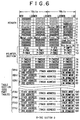
- FIG. 6 shows the format of U-TOC sector 0.
- sector 0 through sector 32 can be provided.
- Sector 1 and sector 4 provides areas for recording character information and sector 2 provides area for recording a date of recording.
- U-TOC sector 0 will be described which is always necessary for a recording and/or reproducing operation on the disc 90.
- U-TOC sector 0 provides a data area recording control information about a program such as music mainly recorded by a user and a free area in which additional programs are recorded.
- the system controller 11 searches, based on P-FRA, the disc for a free area, which is a recordable area, starting U-TOC sector 0 and records the music in the retrieved free area. In a reproducing operation, based on U-TOC sector 0, the system controller 11 determines an area in which a piece of music to be reproduced is recorded and accesses that area for reproduction.
- the synchronous patterns are followed by addresses providing cluster address (cluster H and cluster L) and a sector address (sector) in three consecutive bytes. These addresses are followed by one byte of mode information (MODE). These four bytes forms a header. The addresses of three bytes provide an address of that sector itself.
- the header in which synchronous patterns and addresses are recorded is the same as those of P-TOC sector, AUX-TOC sector, AUX file sector, and program sector. Therefore, the headers of these sectors are skipped from the descriptions of these sectors with reference to FIG. 8 and subsequent drawings.
- the address and synchronous patterns of a particular sector are recorded on a sector basis.
- cluster address is represented in two bytes of high-order address (cluster H) and low-order address (cluster L) and the sector address is represented in one byte.
- cluster H high-order address
- cluster L low-order address
- the address of each sector is not a short-form address.
- a maker code indicative of manufacturer a model code indicative of a model of the apparatus by which recording has been performed, a first track number (First TN0), a last track number (Last TN0), a sector usage state (Used sectors), a disc serial number, and a disc ID are recorded at predetermined byte positions.
- an area is prepared in which various pointers (P-DFA (Pointer for Defective Area), P-EMPTY (Pointer for Empty Slot), P-FRA (Pointer for Free Area), and P-TN01 through P-TN0255) are recorded as a pointer section for identifying the areas of programs such as music recorded by the user and the free areas, which are recordable areas, by relating them to a table section to be described later.
- P-DFA Pointer for Defective Area
- P-EMPTY Pointer for Empty Slot
- P-FRA Pointer for Free Area
- P-TN01 through P-TN0255 are recorded as a pointer section for identifying the areas of programs such as music recorded by the user and the free areas, which are recordable areas, by relating them to a table section to be described later.
- the pointer section is followed by the table section composed of 255 part tables 01h through FFh to be related to the pointers (P-DFA through P-TN0255).
- Each part table records a start address providing the origin of a particular part, an end address providing the end point of that part, and mode information (track mode) about that part are recorded.
- a part listed in one part table may be linked to another, so that link information indicative of the part table in which the start and end addresses of the destination part can be recorded in the table section.
- a part denotes a track part in which pieces of data consecutive in time are physically consecutively recorded in one track.
- the address indicated by the start address and the end address provides an address indicative of one or more parts constituting one piece of music.
- These addresses are recorded in the short form to specify a cluster, a sector therein, and a sound group therein.
- link information is provided.
- part tables to be linked can be linked by specifying them by numbers 01h through FFh assigned to the part tables.
- one part table represents one part.
- the positions of these parts are controlled by the part tables linked by the link information.
- the link information is indicated by a value, which is a byte position in U-TOC sector 0, by predetermined computation.
- the part table is specified by 304 + (link information) x 8 (8th byte).
- the contents of the part tables 01h through FFh in the table section of U-TOC sector 0 are indicated as follows by the pointers (P-DFA, P-EMPTY, P-FRA and P-TN01 through P-TN0255) of the pointer section.
- the pointer P-EMPTY points at the beginning part table of one or more empty part tables in the control table section. If an empty part table exists, one of 01h through FFh is recorded as the pointer P-EMPTY.
- the part tables are sequentially specified by link information starting with one specified by the pointer P-EMPTY, linking all empty part tables in the control table section.
- the pointer P-FRA points at a free area (including an erase area) on the magneto-optical disc 90, in which data can be written.
- FIG. 7 schematically shows, by way of part tables, a control state of parts providing free areas. This shows that, if parts 03h, 18h, 1Fh, 2Bh, and E3h are free areas, this state is represented by the linking of the part tables 03h, 18h, 1Fh, 2Bh, and E3h after the pointer P-FRA. It should be noted that this holds true with the control form of the above-mentioned defective areas and empty part tables.
- the pointers P-TN01 through P-TN255 point at programs of music for example recorded on the magneto-optical disc 90 by the user.
- the pointer P-TN01 points at a part table indicating a beginning part in time of one or more parts recorded with the data of the first track.
- the record area of the first track is recorded as the start and end addresses of the part table pointed by the pointer P-TN01.
- the parts indicative of the record position of the second track are specified sequentially in time. Namely, starting with the part table pointed by the pointer P-TN02, other part tables are sequentially specified by the link information up to the part table at which the link information is "00h" (in the same form shown in FIG. 7).
- the area control on the disc is performed by P-TOC and the control of the music recorded in the recordable user area and the control of free areas are performed by U-TOC.
- the sector 1 is a data area for recording character information inputted when track names are assigned to recorded tracks and a disc name is attached to the disc itself.
- U-TOC sector 1 has a pointer section containing pointers P-TNA1 through P-TNA255 corresponding to recorded tracks.
- U-TOC sector 1 also has a slot section containing 255 8-byte slots (01h through FFh) plus one 8-byte slot that are specifiable by the pointers P-TNA1 through P-TNA255.
- U-TOC sector 1 controls the character information in generally the same manner as the above-mentioned U-TOC sector 0.
- the slot specified by pointer P-TNA1 records characters inputted by the user for the first track. Slots are linked together by link information, so that the number of characters exceeding 7 bytes (or 7 characters) can be inputted for one track.
- the pointer P-EMPTY also controls empty slots.
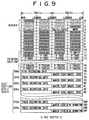
- This sector 2 is a data area for mainly recording a date at which the user recorded music.
- U-TOC sector 2 has a pointer section containing pointers P-TRD1 through P-TRD255 corresponding to the recorded tracks and a slot section containing slots to be specified by these pointers.
- the slot section has 255 8-byte slots 01h through FFh, controlling the date data in generally the same manner as the above-mentioned U-TOC sector 0.
- Each of the slots 01h through FFh records a music (or track) recording date in six bytes. These six bytes record values corresponding to year, month, day, hour, minute, and second respectively.
- the remaining two bytes of each 8-byte slot record a maker code and a model code, namely code data indicative of the manufacturer of the recording apparatus that recorded the music and code data indicative of the model of that recording apparatus.
- the slot specified by pointer P-TRD1 records the recording date, the maker code, and the model code.
- the recording date data is automatically recorded by the system controller 11 by referencing the internal clock of the recording apparatus.
- the 8 bytes as a slot (00h) provide an area dedicated to the recording of recording date on a disc basis, so that this slot is not specified by some pointers P-TRD(x).
- the slot pointer P-EMPTY also controls the empty slots.
- link information is recorded instead of the model code. With the slot pointer P-EMPTY located at the beginning of each empty slot, the empty slots are linked by link information for control.
- FIG. 10 shows U-TOC sector 4. Like the above-mentioned sector 1, the sector 4 provides a data area for recording character information inputted by the user when attaching a music title to a track recorded by the user or a disc name to the disc. As seen from comparison between FIGS. 10 and 8, the format of the sector 4 is generally the same as that of the sector 1.
- the sector 4 is adapted to record code data (a 2-byte code) for kanji and European characters.
- code data a 2-byte code
- character code attributes are recorded at predetermined byte positions as shown in FIG. 10.
- the character information of U-TOC sector 4 is controlled by pointers P-TNA1 through P-TNA255 and the 255 slots 01h through FFh specified by the pointers P-TNA1 through P-TNA255.
- the recording and/or reproducing apparatus 1 practiced as the present preferred embodiment supports the reproduction-only disc with no U-TOC formed; in the case of reproduction-only discs, character information about the disc name and track names can be stored in P-TOC.
- the P-TOC sector a sector generally the same as U-TOC sectors 1 and 4 is prepared.
- the disc manufacturer can record the disc name and track names in this P-TOC sector beforehand.
- an area for recording the AUX data file and AUX-TOC as described with reference to FIGS. 5A and 5B is set to record character information and image information as an AUX data file independently of a program such as music for example.
- the AUX data file is controlled by AUX-TOC.
- This AUX-TOC is recorded in each of three consecutive clusters. Therefore, in control data structure, 32 sectors in one cluster can be used as with U-TOC.
- AUX-TOC sectors 0 through 9 are set to control the AUX data files as described below.
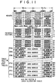
- AUX-TOC sector 0 provides an area allocation table for mainly controlling the AUX data area in its entirety.
- this sector 0 records a maker code, a model code, backup information, an ASPB (Auto Sequence Play Back) flag, and used sector information in this order at respective predetermined byte positions following the header.
- the ASPB flag indicates that a still picture, a text, and a karaoke text, for example, as AUX data files are outputted in synchronization with the reproduction of music as a program.
- the sector usage state recorded in AUX-TOC is displayed.
- This AUX-TOC sector 0 has a pointer section containing pointers P-DFAA, P-EMPTY, P-BLANK, P-SPICT, P-TEXT, and P-KRAOK.
- a table section of this sector 0 contains 255 8-byte part tables for recording start addresses, end addresses, and link information.
- the AUX data area is controlled in the same manner as the above-mentioned U-TOC sector 0.
- the pointer P-DFAA (pointer for defective area of auxiliary data area) controls a defective area in the AUX data area by the start and end addresses recorded in the specified part table. If there are two or more defective areas, other part tables are linked by link information.
- the pointer P-EMPTY (Pointer for Empty Slot) controls empty part tables in this AUX-TOC sector 0 in a linked form.
- the pointer P-BLANK (Pointer for Blank Area) controls, in a part table linked form, an area in which free areas in the AUX data area, namely AUX data files can be recorded, like the pointer P-FRA in the U-TOC sector 0.
- the pointer P-SPICT (Pointer for Still Picture) controls, in a part table linked form, an area for recording a still picture data file (namely a picture file sector to be described later) in the AUX data area. It should be noted that one picture file consists of one or two clusters. Therefore, the still picture data file area to be controlled by the pointer P-SPICT is a cluster-based area.
- the pointer P-TEXT (Pointer for TEXT data) controls, by part table link information, an area for recording a text file (namely a text file sector to be described later) in the AUX data area. It should be noted that the file length of one text file is one sector. However, the text file area to be controlled by the pointer P-TEXT is a cluster-based area.
- the pointer P-KRAOK (Pointer for Karaoke data) controls, in a part table linked form, an area for recording a karaoke text file (namely a karaoke text file sector and a karaoke address sector to be described later) in the AUX data area.
- a karaoke text file namely a karaoke text file sector and a karaoke address sector to be described later
- one karaoke text file is a file based on one or two sectors corresponding to one program.
- the text data file area controlled by the pointer P-KRAOK is based on cluster.
- the pointers P-SPICT, P-TEXT, and P-KRAOK control the areas for recording a picture (still picture) file, a text file, and a karaoke text file in the AUX data area by the start and end addresses as the area address in part tables. Therefore, according to the control state in the sector 0, each of the above-mentioned areas can be dividably set freely or the length of each area can be set freely.
- start address and the end address are of short form and specifiable up to the sound group position.
- the pointers for identifying the types of AUX files are P-SPICT, P-TEXT, and P-KRAOK. If a file other than the picture file, the text file, and the karaoke file is to be recorded as an AUX data file, a pointer corresponding to the type of that file may be set for area control.
- the pointer section can contain pointers corresponding to a maximum of 255 types of files including P-SPICT, P-TEXT, and P-KRAOK.
- AUX-TOC sectors 1 through 5 are used for controlling a picture file as still picture information.
- the AUX-TOC sector 1 shown in FIG. 12 provides a control sector as a still picture allocation table to control the data files recorded as picture files in the picture file area set by the pointer P-SPICT in the above-mentioned AUX-TOC sector 0.
- the picture files are controlled in the same manner as the U-TOC sector 0.
- the length of the picture file for one piece of still picture to be recorded in the AUX data area is one cluster or two clusters in the present embodiment. If one file is one cluster long, the AUX data area can record up to 38 pieces of picture files.
- One of these picture files provides a so-called disc cover image (a cover picture providing a disc cover for example).
- pointers P-PN0(x) For pointers P-PN0(x) that are used for controlling 37 picture files other than the cover picture file, pointers P-PN01 through P-PN037 are formed in the AUX-TOC sector 1. However, in order to accommodate a future expansion of the AUX data area and a future file size change to record more picture files, pointers P-PN0(x) can be set up to P-PN0255 as shown in the parentheses in FIG. 12.
- pointers P-PFRA and P-EMPTY are also formed.
- 255 part tables 01h through FFh each for recording a start address, an end address, and a picture mode (or SPICT mode) are formed as 8-byte part tables corresponding to the above-mentioned pointers in the pointer section.
- the part table 00h is not specified by some pointers. In the present embodiment, this part table is used only to control the address of a picture file that provides a cover picture.
- Pointers P-PN01 through P-PN037 controls areas each recording one picture file by specifying a particular part table.
- the part table specified by pointer P-PN01 records the start address, end address, and image mode (or SPICT mode) of the picture file that provides the first piece of image data.
- the AUX-TOC sector 1 does not perform file control by linking part tables by link information. Namely, one picture file is not recorded discretely over physically separated sections.
- the empty part tables in this sector are controlled in a linked form (the 8th byte in the part table provides the link information) with the pointer P-EMPTY used as the origin.
- the pointer P-PFRA controls the free areas, namely the picture file recordable areas in the picture file area set by the pointer P-SPICT in the above-mentioned AUX-TOC sector 0.
- the address of the section providing a free area is recorded in the part table specified by the pointer P-PFRA.
- part tables are sometimes linked by the link information provided by the 8th byte in each part table, controlling two or more separated sections as free areas.
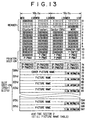
- FIG. 13 shows the format of the AUX-TOC sector 2.
- the sector 2 provides a still picture name table.
- the sector 2 is a data area for recording character information that provides the picture name.
- the AUX-TOC sector 2 has a pointer section containing pointers P-PNA1 through P-PNA37 (expandable to P-TNA255) corresponding to the recorded picture files.
- This sector also has a slot section containing 255 8-byte slots 01h through FFh and one 8-byte slot 00h to be specified by the pointers P-TNA1 through P-TNA37.
- the slots 00h through FFh record character information as a picture name in an ASCII code or another character code.
- the type of characters to be recorded is recorded at a predetermined byte position as a character code.
- 00h is represented in an ASCII code
- 01h is represented in a modified ISO (International Standard Organization) 8859-1 code
- 02h is represented in a music-shifted JIS (Japanese Industry Standard) code for example.
- the pointers P-PNA1 through P-PNA37 each specify a particular part table recording a picture name for one picture file.
- the slot specified by the pointer P-PNA1 records characters corresponding to the image of the first picture file. Linking slots by use of linking information allows a picture name for one picture file to be made larger than 7 bytes (or 7 characters).
- the pointer P-EMPTY controls empty slots in a linked form.
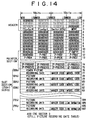
- FIG. 14 shows the format of the AUX-TOC sector 3.
- the sector 3 is a still picture recording date table and provides a data area for controlling the record date at which a picture file was recorded.
- the AUX-TOC sector 3 has a pointer section containing pointers P-PRD1 through P-PRD37 (expandable to P-PRD255) corresponding to the recorded picture files.
- This sector also has a slot section to be specified by these pointers P-PRD1 through P-PRD37.
- the slot section contains 255 8-byte slots 01h through FFh and one 8-byte slot 00h to control the date data in generally the same manner as the above-mentioned U-TOC sector 2.
- the slots 01h through FFh each record a picture file recording date in six bytes. These six bytes record values representing year, month, day, hour, minute, and second respectively. The remaining two bytes record a maker code and a model code, namely code data indicative of the manufacturer of the recording apparatus that recorded the music and code data indicative of the model of that recording apparatus.
- the slot specified by pointer P-PRD1 records the recording date, the maker code, and the model code.
- the recording date data is automatically recorded by the system controller 11 by referencing the internal clock of the recording apparatus.
- the 8 bytes as a slot (00h) provide an area dedicated to the recording of recording date of the cover picture, so that this slot is not specified by some pointers P-PRD(x).
- the slot pointer P-EMPTY also controls the empty slots.
- link information is recorded instead of the model code.
- the empty slots are linked by link information for control.
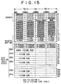
- FIG. 15 shows the format of the AUX-TOC sector 4.
- the sector 4 provides a still picture code table for recording code information of recorded picture files.
- the AUX-TOC sector 4 has a pointer section containing pointers P-PCD1 through P-PCD37 (expandable to P-PCD255) corresponding to the recorded picture files.
- This sector also has a slot section to be specified by these pointers P-PCD1 through P-PCD37.
- the slot section contains 255 8-byte slots 01h through FFh and one 8-byte slot 00h.
- the slot specified by the pointer P-PCD1 records the code information of that picture file.
- the 8 bytes as a slot (00h) provide an area dedicated to the recording of the code information of the cover picture file, so that this slot is not specified by some pointers P-PCD(x).
- the pointer P-EMPTY also controls the empty slots.
- the AUX-TOC sector 5 shown in FIG. 16 provides a still picture playback sequence table.
- This table provides control information for outputting (namely displaying an image) a picture file in synchronization with reproduction of a program such as music.
- the sector 5 contains pointers P-TN01 through P-TN0255. These pointers are the same as those of the U-TOC sector 0 and correspond to tracks 1 through 255 as programs such as music.
- a part table section of the sector 5 contains 255 8-byte part tables 01h through FFh, which are specified by the pointers P-TN01 through P-TN0255.
- the part table section also has one part table 00h that is not specified by these pointers.
- the part tables specified by the pointers P-TN01 through P-TN0255 each record the start and end addresses, which are offset addresses from the start position address of that track.
- Particular picture files are identified by pointer P-PN0(*).
- the pointer P-PN0(*) has a value equivalent to each picture file controlled by the AUX-TOC sector 1. Further, this pointer can link other part tables by link information.
- the start and end addresses defining an image output period are recorded in the part table specified by the pointer P-TN01 and a particular picture file is indicated by the pointer P-PN0(*) as the image to be outputted.
- an address point equivalent to one minute zero second after starting the reproduction of the first track and an address point equivalent to one minute 30 seconds after starting that reproduction are recorded in the part table specified by the pointer P-TN01 as the start address and the end address respectively in an offset address relation. Then, the pointer P-PN0(*) takes the value of pointer P-PN01 to specify the first picture file.
- the corresponding part tables are linked to control the picture files to be outputted and the output period.
- start and end addresses as the output timing of a picture file providing the cover picture are recorded in the part table 00h.
- the pointer P-EMPTY also controls the empty part tables.
- the AUX-TOC sector 6 and the AUX-TOC sector 7 are used for controlling text files.
- the AUX-TOC sector 6 shown in FIG. 17 provides a control sector as a text allocation table to control the data files recorded as text files in a text file area set by pointer P-TEXT in the above-mentioned AUX-TOC sector 0.
- AUX data area is all used for recording text files, 38 clusters (x 32 sectors x 2324 bytes) of text data can be recorded. This text data can be controlled in the AUX-TOC sector 6 as a maximum of 255 files.
- each text file is based on sector.
- One particular text file can be positioned as a text file (or a cover text) corresponding to a so-called disc cover picture.
- pointers P-TXT(x) for use in controlling text files pointers P-TXT1 through P-TXT255 are formed in the AUX-TOC sector 6.
- pointers P-TFRA and P-EMPTY are also formed.
- the table section of this sector contains 255 8-byte part tables 01h through FFh, each part table recording a start address, an end address, and a character mode and a superimposed bit.
- the part table 00h is not specified by any pointer. This table is used only for controlling the addresses and character code of the text file positioned as a cover text.
- the pointers P-TXT1 through P-TXT255 control areas each recording one text file by specifying particular part tables.
- the part table specified by the pointer P-TXT1 records the start and end addresses and character code and a superimposed bit of the first text file.
- the AUX-TOC sector 6 does not perform the file control operation in which part tables are linked by use of link information. Namely, no one text file is recorded over physically separated sections.
- the pointer P-TFRA controls the free areas, or the text file recordable areas in the text file area set by the pointer P-TEXT in the AUX-TOC sector 0.
- the addresses of a section, which is a free area, are recorded in the part table specified by the pointer P-TFRA.
- part tables are linked by the link information provided by the 8th byte of each part table, sometimes controlling two or more separated sections as free areas.
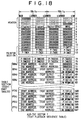
- the AUX-TOC sector 7 shown in FIG. 18 provides a text playback sequence table.
- This table provides control information for outputting a text file in synchronization with the reproduction of a program such as music.
- the sector 7 has pointers P-TN01 through P-TN0255. These pointers are the same as those described with reference to the U-TOC sector 0 and correspond to tracks 1 through 255 as programs such as music.
- the part table section of the sector 7 contains 255 8-byte part tables 01h through FFh to be specified by the pointers P-TN01 through P-TN0255.
- One 8-byte part table 00h that is not specified by these pointers is also formed in the table section.
- control form in this sector is generally the same as that in the above-mentioned AUX-TOC sector 5.
- the part tables specified by the pointers P-TN01 through P-TN0255 each record the start and end addresses, which are offset addresses from the start position address of that track.
- Particular text files are identified by pointer P-TXT(*).
- the pointer P-TXT(*) has a value equivalent to each text file controlled by the AUX-TOC sector 6. Further, this pointer can link other part tables by link information.
- the start and end addresses defining a character output period are recorded in the offset address format in the part table specified by the pointer P-TN01 and a particular text file is indicated by the pointer P-TXT(*) as the character to be outputted. If it is desired to output two or more pieces of character information during reproduction of one track, corresponding part tables are linked to control the text files to be outputted and the output period.
- start and end addresses as the output timing of a text file providing the cover text are recorded in the part table 00h.
- the pointer P-EMPTY also controls the empty part tables.
- the AUX-TOC sector 8 and sector 9 are for use in controlling karaoke text files.
- a karaoke text file denotes a text file for displaying character information providing a lyrics text for example in synchronization with the music to be outputted.
- a karaoke text file sector recording character information such as lyrics text and a karaoke address sector for finely setting a character output timing are recorded in a pair.
- one karaoke text file to be recorded in one track is composed of two sectors, namely the karaoke text file sector and the karaoke address sector.
- the sector 8 mainly controls the karaoke text file sector while the sector 9 mainly controls the karaoke address sector.
- the AUX-TOC sector 8 shown in FIG. 19 provides a control sector as a karaoke text allocation table.
- This control sector controls the data files (karaoke file data sectors) recorded as karaoke text files in a karaoke text file area set by the pointer P-KRAOK in the above-mentioned AUX-TOC sector 0.
- the AUX-TOC sector 8 controls the karaoke text files in the same manner as the U-TOC sector 0.
- a maximum of 255 tracks can be recorded as programs, so that a maximum of 255 karaoke text files corresponding to these tracks may be controlled.
- the pointers P-TN01 through P-TN0255 used in the U-TOC sector 0 are used in this AUX-TOC sector 8 without change for controlling these karaoke text files.
- the pointers P-KFRA and P-EMPTY are also formed in the sector 8.
- the table section of this sector contains 255 8-byte part tables 01h through FFh, each part table recording a start address, an end address, and a character code (to be specific, a character code and a superimposed bit).
- the pointers P-TN01 through P-TN0255 control areas each recording one karaoke text file by specifying particular part tables.
- the part table specified by the pointer P-TXT1 records the start and end addresses and character mode and a superimposed bit of a karaoke text file sector corresponding to the first track.
- the AUX-TOC sector 8 does not perform the file control operation in which part tables are linked by use of link information. Namely, no one karaoke text file is recorded over physically separated sections.
- the pointer P-KFRA controls the free areas, or the karaoke text file recordable areas in the karaoke text file area set by the pointer P-KRAOK in the AUX-TOC sector 0.
- the addresses of a section, which is a free area, are recorded in the part table specified by the pointer P-KFRA.
- part tables are linked by the link information provided by the 8th byte of each part table, sometimes controlling two or more separated sections as free areas.
- the AUX-TOC sector 8 controls the karaoke text file sector constituting a karaoke text file.
- the AUX-TOC sector 9 controls the karaoke address sector to be recorded in a pair with the karaoke text file sector for finely setting the output timing of the character information recorded in the karaoke text file sector.
- the sector 9 specifies part tables each recording the address of a corresponding karaoke address sector by track-corresponding pointers P-TN01 through P-TN0255.
- each 8-byte part table corresponding to each of these pointers records the start and end addresses of a karaoke address file.
- the pointers P-TN01 through P-TN0225 each control the address of a karaoke address sector in one karaoke text file corresponding to one of the tracks 1 through 255 by specifying a particular part table.
- the part table specified by the pointer P-TN01 records the start and end addresses of the karaoke address sector to be paired with the karaoke text file sector controlled by the above-mentioned AUX-TOC sector 8 in correspondence with the first track.
- the AUX-TOC sector 9 does not perform the file control operation in which part tables are linked by use of link information. Namely, no one karaoke address file is recorded over physically separated sections.
- the karaoke text file sector and the karaoke address sector constituting a karaoke text file corresponding to each track are controlled in a pair.
- the actual output timing of the character information recorded in the karaoke text file sector is set by the karaoke address sector. The method of this setting and the output operation will be described later.
- the file length of one piece of still picture, namely the size of one picture file is equivalent to one cluster or two clusters.
- a picture file is as long as one cluster, a maximum of 37 picture files plus one cover picture file can be recorded in the AUX data area.
- One still picture consists of 640 x 480 dots.
- Each picture file is based on JPEG (Joint Photographic Coding Expert Group) format.
- Each picture file is controlled by AUX-TOC, so that the file bit stream is from the SOI marker specified by JPEG to the EOI marker of the file.
- mode 2 For the sector format, mode 2 is used and no third-layer ECC (Error Correction Code) is practiced, so that the image data capacity of one sector is 2324 bytes or the capacity of one cluster is 74368 bytes.
- ECC Error Correction Code
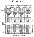
- the format of sectors constituting a cluster that provide the above-mentioned picture file is as shown in FIG. 21 for example.
- EDC0 through EDC3 are recorded.
- text data such as ASCII, Modified ISO 8859-1, and Music Shifted JIS can be recorded.
- the sector as a text file records characters and control codes.
- the control codes include a line feed, a page feed, and the like information.
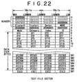
- the format of the sector constituting a text file is as shown in FIG. 22 for example. Like a picture file, a header, error correction mode information (Mode), category information (Category), index information (Index), and a system identifier (ID) are arranged in this order. After these pieces of information, 2324 byte of character information (and control codes) as indicated by data DT0 through DT2323 are recorded.
- EDC0 through EDC3 are recorded.
- each karaoke text file is constituted in which a karaoke text file sector and a karaoke address sector are paired.
- the character information such as a lyrics text recorded in the karaoke text file sector is outputted for display based on the address information recorded in the karaoke address sector in a timed relation synchronized with the song or accompaniment of the corresponding track.
- the karaoke text file sector can record text data such as ASCII, Modified ISO 8859-1, and Music Shifted JIS.
- the karaoke text file sector also records various control codes for specifying character display position on screen, font, color, line feed, wipe, and so on.
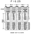
- a karaoke text file sector that constitutes, in a pair with a karaoke address sector to be described later, one karaoke text file is as shown in FIG. 23 for example.
- a header error correction mode information (Mode), category information (Category), index information (Index), and a system identifier (ID) are arranged in this order. After these pieces of information, 2324 byte of character information and control codes as indicated by data DK0 through DK2323 are recorded.
- EDC0 through EDC3 are recorded.
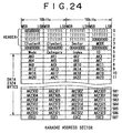
- FIG. 24 The format of a karaoke address sector paired with the karaoke text file sector shown in FIG. 23 is shown in FIG. 24. Also like a picture file, a header, error correction mode information (Mode), category information (Category), index information (Index), and a system identifier (ID) are arranged in this order. After these pieces of information, 2324 byte of character information (and control codes) as indicated by data AK0 through AK2323 are recorded.
- Mode error correction mode information
- Category information Category information
- Index index information
- ID system identifier
- one address is represented in four bytes (each of cluster addresses, a sector address, or a sound group address).
- one address is recorded in four bytes, for example address data AK0 through AK3, that form one line in FIG. 24.
- the cluster, sector, and sound group addresses are represented in a 3-byte short form, the remaining one byte being dummy.
- the karaoke address sector can record up to 581 address values per sector, or specify 581 timings (or offset addresses from track start address) in a corresponding piece of music as a track.
- specifying the start and end address of each part table in the AUX-TOC sectors 8 and 9 can arbitrarily set the lengths of the karaoke text file and karaoke address file for one piece of music on a sector basis.
- the data files as AUX data and the AUX-TOC sectors for controlling these data files are formed as described above.
- Each data file can perform output such as image display and character display in synchronization with the reproduction of a program. The following describes this data file reproducing operation.
- Each picture file is controlled by the AUX-TOC sector 1, so that the system controller 11 can output the picture file at any point of time for display.
- the system controller 11 can display the picture file on the display monitor 24 or an externally attached monitor device through the interface 25.
- system controller 11 can display the picture names and recording dates controlled by the AUX-TOC sectors 2 and 3 onto the display monitor 24 for example at displaying images as pictures.
- the system controller 11 can execute the display output of a predetermined picture file in synchronization with a program. For example, as described in the AUX-TOC sector 5, the system controller 11 can, during reproduction of music of a certain track, output and display an image as one or more picture files in a particular timed relation indicated as the start and end addresses.
- the output operation of a picture file can also be performed on a text file.
- the system controller 11 can output a text file for character display at any point of time.
- the system controller 11 can display a text file on the display monitor 24 or an externally attached monitor device through the interface 25.
- the system controller 11 can execute display output of a predetermined text file in synchronization with the reproduction of a program. For example, as described in the AUX-TOC sector 5, the system controller 11 can, during reproduction of music of a certain track, output and display an image as one or more text files in a particular timed relation indicated as the start and end addresses.
- the system controller 11 can output and display a karaoke text file in synchronization with the reproduction of music as a track, or the character information as a lyrics text in synchronization with the play of music as a vocal or a karaoke guide.
- each karaoke text file is formed for one track and each karaoke text file thus formed is constituted by a pair of karaoke text file sector and karaoke address sector.
- FIGS. 25A shows an example of information in the karaoke text file sector shown in FIG. 23 to be recorded as data DK0 through DK7.
- Values 59h, 6Fh, ..., 77h representing data DK0 through DK7 provide character information in ASCII code. As shown, this example records character information "Y”, “o”, “u”, “ “, “k”, “n”, “o”, and "w” forming a part of the lyrics text of a track as data DK0 through DK7.
- FIG. 25B shows an example of information in the karaoke address sector to be recorded as address data AK0 through AK7.
- the address is represented in the short form by use of three of the four bytes. Therefore, one offset address is recorded as address data AK0 through AK3 and another offset address is recorded as address data AK4 through AK7.
- address values "cluster 0032h, sector 04h, sound group 0h” and the address values "cluster 0032h, sector 13h, sound group 9h” shown in FIG. 4 are recorded as offset addresses starting from the address values "cluster 0032h, sector 00h, sound group 0h" respectively.
- the karaoke text file sector and the karaoke address sector shown in FIGS. 25A and 25B are controlled as a pair of sectors by the AUX-TOC sectors 8 and 9.
- the address data AK0 through AK3 of the karaoke address sector provide an address corresponding to the data DK0 through DK3 of the karaoke text file sector.
- the address data AK4 through AK7 of the karaoke address sector provide an address corresponding to the data DK4 through DK7 of the karaoke text file sector.
- the karaoke address sector and the karaoke text file sector are related to each other on a 4-byte basis. Namely, as shown in FIGS. 23 and 24, data DK8 through DK11 correspond to address data AK8 through AK11, data DK12 through DK15 correspond to address data AK12 through AK15, ..., and data DK2320 through DK2323 correspond to address data AK2320 through AK2323.
- the addresses as output timings are recorded in the karaoke address sector on a 4-byte basis.
- This arrangement allows the system controller 11 to know that characters "You” for example shown in FIG. 25A is to be outputted in the reproduction timing of "cluster 0032h, sector 04h, sound group 0h” shown in FIG. 25B and that characters "Know” shown in FIG. 25A is to be outputted in the reproduction timing of "cluster 0032h, sector 13h, sound group 9h” shown in FIG. 25B.
- the output timing of the character information providing a lyrics text is thus controlled on a 4-byte basis, so that presetting the address data providing this output timing in a matched relation with a piece of music can output and display the characters forming a lyrics text in synchronization with the song or accompaniment of the music.
- the lyrics text to be sung is displayed in an appropriate timed relation.
- the lyrics text of a song can be displayed in synchronization with the song, thereby extending user's musical enjoyment.
- FIG. 25C shows an example in which address information is represented not in an offset address but in an absolute address (or a short form).
- an output timing may be specified in an absolute address.
- FIGS. 25B and 25C show examples in which addresses are recorded in the short form. However, the addresses may not always be represented in the short form because the 4-byte area is allocated.
- the U-TOC area is reproduced in step S101 and data such as the recording position of each music in the program area is stored in memory in step S102.
- the AUX-UTOC area is reproduced to tabulate various file number information corresponding to the recording position and music number in the AUX data area in which a picture file, a text file, and a karaoke file are recorded and the timing information for synchronous reproduction.
- the resultant table is stored in memory in step S104.
- step S105 auxiliary data is reproduced from the AUX data area and the reproduced auxiliary data is stored in memory in step S106.
- the optical pickup is moved to the program area in which music is recorded to start reproducing audio data.
- step S108 in synchronization with the reproduction of the audio data, the image, text, lyrics text data corresponding to the currently reproduced music number are outputted from memory in a predetermined timed relation based on the various file number information corresponding to the music number reproduced from the AUX-UTOC area and the timing information for synchronous reproduction stored in memory.
- auxiliary data including the image, text, and lyrics text data outputted from memory in the predetermined time relation are displayed on a monitor display such as CRT in step S109.
- step S110 it is determined whether all pieces of music have been reproduced. If not, then back in step S108, the auxiliary data for the music number being reproduced is synchronously reproduced.
- step S111 If yes, the reproduction of the music in the program area and the reproduction of the auxiliary data from memory are ended in step S111.
- the memory device for storing the above-mentioned U-TOC data, AUX-UTOC data, and auxiliary data may be one memory device or two or more memory devices provided in correspondence with the above-mentioned types of data. If the auxiliary data is image data, a memory device of a relatively large storage size is required in general.
- the AUX data file that can be outputted for reproduction as described above can be recorded on the disc 90 by the user after (or at the same time) a piece of music has been recorded as a program.
- the user inputs character data and image data by operating the operator panel 23 or a personal computer or an image scanner connected to the present embodiment through the interface 25.
- the user may or may not input a track number or output timing information of a program to be related.
- the system controller 11 controls the recording operation on the disc 90 such that the inputted image data or character data is recorded as one picture file or one text file in the AUX data area. At the same time, the system controller 11 updates the AUX-TOC such that the recorded data file is controlled by the AUX-TOC sector 1 or sector 6.
- the system controller 11 records the picture file or a text file onto the disc 90 and updates the AUX-TOC sector 1 or sector 6 as well as the AUX-TOC sector 5 or sector 7 that provides the playback sequence table.
- a control state is realized in which a recorded data file is outputted for display at reproduction of a particular track.
- the start and end addresses of a part table to be used for the specified track are each "000h" in the AUX-TOC sector 5 or sector 7. Namely, a state is provided in which an image or characters as a data file to be recorded are outputted continuously during reproduction of the specified track.
- the values of the start and end address of the part table to be used are set according to this input in the AUX-TOC sector 5 or sector 7. In other words, a state is provided in which the data file is outputted for reproduction in a predetermined period during reproduction of the specified track.
- the reproduction timing may be inputted by allowing the user to turn on a predetermined operator switch in the image or character output start and end timings while having the user be listening to the reproduced audio output of the specified track.
- Specification of the track corresponding to a data file and an output timing setting operation may be performed at the time the data file is recorded as well as at a later time. Namely, an editing operation mode is provided in which the user can arbitrarily execute a data updating operation only for the AUX-TOC sector 5 or sector 7.
- the user can arbitrarily input character data for recording by operating the operator panel 23 or a personal computer connected through the interface 25.
- the user inputs all character data such as the lyrics text of one piece of music for example.
- the system controller 11 requests the user for specification a particular track. The user inputs the track number accordingly.
- the system controller 11 starts reproducing the specified track and, at the same time, displays the characters inputted by the user in units of four bytes from the first character sequentially.
- the user waits for a desired output timing while listening to the reproduced audio and, when that timing comes, the user presses a predetermined timing specifying switch.
- the system controller 11 uses the address of the reproducing position in the timing of this switch pressing operation as the address corresponding to the four bytes of data being displayed. Namely, the system controller 11 holds that address as one of the addresses to be recorded in the karaoke address sector.
- the system controller 11 records, into the AUX data area, the inputted character information as the karaoke text file sector and each address value corresponding to the 4-byte character data that was set as the karaoke address sector. At the same time, the system controller 11 updates the AUX-TOC sector 8 and sector 9.
- karaoke address sector can be updated so that the output timing of each character of the karaoke text file can be adjusted according to the music.
- the present embodiment allows the user to arbitrarily record a picture file, text file, and a karaoke text file and set the output timing in correspondence with a particular track.
- these files can be recorded only by updating these files and the AUX-TOC thereof without updating the corresponding program (or track), so that the recording can be executed in a significantly short time.
- the output timings can be changed or adjusted and tracks to be related can be easily changed only by updating the AUX-TOC.
- step S201 When a recording operation is instructed, the U-TOC area is first reproduced in step S201.
- step S202 data such as the recording position of each piece of music in the program area is stored in memory.
- step S203 the AUX-UTOC area is reproduced to tabulate various file number information corresponding to the recording position and music number in the AUX data area in which a picture file, a text file, and a karaoke file are recorded and timing information for synchronous reproduction.
- the resultant table is stored in memory in step S204.
- step S205 auxiliary data is reproduced from the AUX data area.
- the reproduced auxiliary data is once saved in memory in step S206.
- step S207 image or text data supplied from a personal computer, digital still camera, or an image scanner for example through the interface is additionally written from the AUX data area saved in memory onto the auxiliary data.
- step S208 whether an operation for relating the auxiliary data composed of the image or text data captured through the interface with the music already recorded in the program area is to performed or not is made by use of the operator panel 23 shown in FIG. 1.
- step S208 If the relating operation is determined to be performed in step S208, a music number to be related is selected. In step S209, the music corresponding to the music number selected in step S208 is reproduced. If it is desired to synchronously reproduce the still image or text data captured in a desired timed relation for the output of the audio signal being reproduced, the user specifies a period of the synchronous reproduction in steps S210 through S213.
- step S210 while listening to the audio signal being reproduced, the user performs a predetermined operation on the operator panel 23 shown in FIG. 1 at the position at which the synchronous reproduction of the still image or text data is to start.
- step S211 the offset address of the position being reproduced when the above-mentioned predetermined operation was performed is stored in memory.
- step S212 while listening to the audio signal being reproduced, the user performs a predetermined operation on the operator panel 23 shown in FIG. 1 at the position at which the synchronous reproduction of the still image or text data is to be ended.
- step S213 the offset address of the position being reproduced when the above-mentioned predetermined operation was performed is stored in memory.
- step S208 only the music number is specified and the synchronous reproduction start position and the synchronous reproduction end position are not specified in steps S210 and S212 respectively, then, in step S214, "000h" is stored in memory as the start address and the end address to be stored in memory.
- step S215 the music number specified in step S208 is stored in memory.
- step S216 the additionally written image or text data stored in memory is recorded onto the AUX data area.
- step S217 the recording position of the image or text data in the AUX data area is stored in memory for control by the AUX-UTOC sector 1 or 6.
- step S217 Based on the recording position information stored in step S217, the AUX-UTOC sector 1 or 6 is edited for updating in step S218.
- step S219 it is determined whether the music number is specified. If not, then, in step S221, this recording operation is ended. If yes, the AUX-UTOC sector 5 or 7 is edited for updating based on the music number, start address, and end address stored in memory.
- Variation A does not use the AUX-TOC sector 9.
- each karaoke text file is composed of a pair of karaoke text file sector and karaoke address sector.
- no karaoke address sector is provided and therefore one karaoke text file is composed of only one karaoke text file sector.
- one track is related to one karaoke text file sector, which is controlled only by the AUX-TOC sector 8, negating the need for the AUX-TOC sector 9.
- the karaoke text file sector is formatted as shown in FIG. 26 for example.
- the header, the error correction mode information (Mode), the category information (Category), the index information (Index), and the system identifier (ID) are the same as those of the above-mentioned nonvariation example.
- an area for recording 1024 bytes of character information (and control codes) is provided as indicated with data DK0 through DK1023.
- An area of the remaining 1024 bytes is used for recording the address information as indicated with address data AK0 through AK1023.
- character information such as a lyrics text and the address information as the output timing of this character information are recorded in one sector.
- the character information such as a lyrics text that can be recorded for one track is 1024 bytes long per sector, a half of the above-mentioned nonvariation example.
- specifying the start and end addresses of part table in the AUX-TOC sector 8 allows the user to arbitrarily set the length of the karaoke text file for one piece of music on a sector basis.
- one piece of address information corresponds to every four bytes of character information.
- data DK0 through DK3 correspond to address data AK0 through AK3
- data DK4 through DK7 correspond to address data AK4 through AK7
- data DK1020 through DK1023 correspond to address data AK1020 through AK1023.
- This arrangement allows the display output of a lyrics text in synchronization with its song or accompaniment like the above-mentioned nonvariation example.
- Variation B also does not require the control by the AUX-TOC sector 9.
- a karaoke text file is formed by a pair of karaoke text file sector and karaoke address sector. Namely, the karaoke text file sector and the karaoke address sector as shown in FIGS. 23 and 24 are provided. Therefore, the size of character information for one track is 2324 bytes.
- the karaoke text file sector for a certain track is specified by the AUX-TOC sector 8.
- the karaoke address sector to be paired with this karaoke text file sector is specified by predetermined rules.
- FIG. 28 shows a cluster that is set in the karaoke text file area.
- the first 16 sectors S00 through S0F are specified each for use as a karaoke text file sector KF and the last 16 sectors S10 through S1F are specified each for use a karaoke address sector AF.
- the karaoke address sector for a certain karaoke text file sector always a sector which is 16 sectors ahead of that karaoke text file sector.
- the karaoke text file sector and the karaoke address sector are related with each other on a one-to-one basis as sectors S00 to sector S10, sector S01 to sector S11, and so on.
- This arrangement also enables the display output of a lyrics text for example which is in synchronization with its song or accompaniment.
- karaoke processing In actual karaoke systems, generally, several lines of a lyrics text which form a totality meaningful as a melody are displayed on the screen beforehand and so-called wipe processing is performed on the displayed characters forming the lyrics lines.
- the wipe processing provides a capability of guiding a karaoke singer along the song being played. For example, the wipe processing sequentially changes the display colors of lyrics characters as the song melody progresses.
- a totality of lyrics text can be displayed in an appropriate timing relation in synchronization with the song or accompaniment for each program (or piece of music) for example.
- comparatively fine display control such as wiping lyrics characters along with the progress of a melody as described above requires definition of predetermined control information for example for the character data and so on.
- the following describes, as the variation C, a karaoke text file format for realizing a practical karaoke lyrics display capability that allows the above-mentioned lyrics wiping processing.
- the variation C does not use the AUX-TOC sector 9 either.
- character information as a karaoke text file and display control information for displaying that character information as actual karaoke lyrics are stored in each sector according to predetermined rules, thereby forming the karaoke text file.
- the area recording one karaoke text file related to each of the tracks 1 through 255 by pointers P-TN01 through P-TN0255 in the AUX-TOC sector 8 shown in FIG. 19 is controlled by specifying a particular part table.
- the start and end addresses of the part table pointed by pointer P-TN0(x) indicate the addresses of the start and end sectors between which the karaoke text file of the track corresponding to that pointer is stored.
- the number of sectors forming the karaoke text file corresponding to one track is not limited, provided that these sectors must be recorded not discretely but continuously in the AUX data area.
- FIG. 29 shows the format of a karaoke text file sector practiced as the variation C. It should be noted that, if two or more sectors form the karaoke text file corresponding to one track, the sector shown in FIG. 29 provides the start sector of that karaoke text file.
- the data of the karaoke text file is recorded in a 2304-byte area formed by slots of lines 12 through 587.
- the byte data in one block is arranged as byte 1 through byte 4 from the upper byte to the lower byte on the top line, and subsequently byte 5, byte 6, ..., byte 23 and byte 24 from the upper byte to the lower byte of line 2, and so on.
- SOL Start Of Line
- SOL indicates that the current block is a block including the start character of a line to be displayed as a karaoke lyrics text.
- SOL is formed by a predetermined fixed bit pattern. Namely, the variation C is controlled by SOL for each character string information forming a lyrics display line.
- CTL, Fnt, P-X, and P-Y are set to byte 2 through byte 5 in block #1 respectively.
- CTL stores information indicative of execution or nonexecution of lyrics wiping, a title, and other required attributes.
- Fnt stores font-associated display information such as the type, size, and color of fonts to be used by lyrics display. For example, this Fnt changes the setting of character color and character attribute before and after the wiping processing or display characters to be described later.
- P-X and P-Y indicates, X coordinate and Y coordinate respectively, a display position (for example, a display start position of a lyrics display line) of the character string information (or lyrics display line) controlled by SOL.
- the following byte 6 through byte 8 store text data.
- the first character of the lyrics display line is stored in byte 6 of the block in which SOL exists.
- text data corresponding to characters a, b, and c, alphabetical characters typical as a 1-byte code are stored in byte 6 through byte 8.
- a Display Start Address is set. For this address, a time (or an address in the corresponding program) at which the lyrics display line controlled by the SOL of the current block is displayed is set.
- the Display Start Address may be represented by any one of the above-mentioned absolute address and offset address.
- Wipe Start and Wide End are set to a 2-byte area formed by byte 13 and byte 14 and a 2-byte area formed by byte 15 and byte 16 respectively.
- Wipe Start indicates a wipe start time (or address) by an offset value for the above-mentioned Display Start Address.
- Wipe End indicates a wipe end time (or address) by an offset value for the above-mentioned Display Start Address.
- Display End is set to a 2-byte area formed by byte 17 and byte 18.
- Display End indicates, by an offset value for the Display Start Address, a time (or address) at which the display of a lyrics display line controlled by the SOL of the current line is ended (or erased).
- Information associated with wipe control on each character information (or text data) stored in the current block is stored in byte 19 through byte 24.
- WL* and PL* are set.
- WL* data equivalent to a duration of time necessary for wiping the character* displayed as a lyrics text is stored.
- PL* a during of time (normally 0 in may cases) from the end of wiping of the character * to the start of wiping of a next character to be wiped is stored.
- WLa and PLa are set to byte 19 and byte 20 of block #1 shown in FIG. 29 respectively as the wipe control information about character "a" stored in byte 6. Subsequently, wipe control information WLb and PLb about the character "b” stored in byte 7 are set to byte 21 and byte 22 respectively. Further, wipe control information WLc and PLc about the character "c" stored in byte 8 are set to byte 23 and byte 24 respectively.
- the block in which SOL is located at byte 1 is a block that includes the start character of karaoke lyrics text display lines.
- This SOL-including block also functions as a header area (subsequently referred to as a header block) that includes such display control information associated with lyrics display lines as CTL, Fnt, P-X, P-Y, Display Start Address, Wipe Start, Wipe End, and Display End. Therefore, since these pieces of display control information must be allocated to the predetermined byte positions in the block as described above, only three characters of text data and wipe control information are stored in the block that has SOL.
- block #2 stores the character information of the same lyrics display line as block #1 and the wipe control information associated with this character information.
- byte 1 through byte 8 of the 24 bytes forming the data block are allocated as an area for storing the text data corresponding to lyrics characters.
- the remaining byte 9 through byte 24 are set as an area in which wipe control information WL* and PL* for the characters (or text data) stored in byte 1 through byte 8 are stored.
- block #1 and block #2 record the text data of one lyrics display line (namely 10 characters “a” through “j") and, at the same time, record the display control information such as lyrics line display timing and position and the wipe timing for each character forming this lyrics display line.
- FIG. 29 shows an example of a state in which the data about the lyrics display line continued from the lyrics display line stored in above-mentioned block #1 and block #2 is stored starting with block #3.
- text data about characters k, l, and m and accompanying wipe control information are stored in block #3.
- karaoke text file data complying with the actual display format of lyrics display line is stored, although not shown.
- the last block #96 stores character information about characters x, y, and z forming a lyrics display line continued from the preceding block and wipe control information (WLx and PLx) through (WLz and PLz) into byte 1 through byte 3 and byte 8 through byte 13 respectively.
- the excess portion may be stored a succeeding sector in the same format as described with reference to FIG. 29.
- the number of continued sectors for storing one piece of music (or one track) is not limited as described before. Actually, any number of sectors may be concatenated that is enough for storing one track of karaoke text file data.
- the data equivalent to one lyrics display line completes only in the block having SOL, the following block being set with a SOL corresponding to the next lyrics display line.
- the block having SOL may be followed by a block having the format described as block #2 may be provided continuously in the number enough for storing the characters forming one lyrics display line.
- the system controller 11 can identify the delimiting position between blocks each corresponding to one lyrics display line by the SOL set to byte 1 of the header block.
- each lyrics display line can be formed and impart variations to the display of a karaoke lyrics text according to the display control information and wipe control information set to this display character line and each character thereof.
- FIGS. 30A through 30D an example of karaoke lyrics display to be realized by the karaoke text file data shown in FIG. 29. It should be noted that it is preferable in reality for the display processing shown in FIGS. 30A through 30D to be performed on a display device having a comparatively large screen such as an externally attached monitor device for example.
- the system controller 11 displays a lyric text of one line of text data characters "a, b, c, d, e, f, g, h, i, and j" at a predetermined position of the display monitor 24 (or an externally attached monitor device) as shown in FIG. 30A based on the data of block #1 and block #2 shown in FIG. 29.
- start of displaying this lyrics display line is timed based on the Display Start Address of block #1 and the display position on the display screen is determined based on P-X and P-Y of block #1.
- the system controller 11 performs timing control on the wipe display for each display characters according to the Wipe Start information of block #1 and the wipe control information set to the text data characters "a, b, c, d, e, f, g, h, i, and j" forming one line of lyrics text.
- This allows these text data characters to be sequentially wiped starting with "a” in synchronization with the progress of the music as shown in FIG. 30B.
- Each wiped character is indicated here by a hollow character for example. In actual wipe processing, the wiped characters may be indicated by any other form such as changed color for example.
- FIG. 30B shows a state in which a lyrics text line based on text data "k, l, m, n, and o" is displayed below a lyrics text line based on text data "a, b, c, d, e, f, g, h, i, and j" in a timed relation in which character "e” is wiped for the case in which the contents of the karaoke text file data shown in FIG.
- a state is indicated in which the lyrics text line "a, b, c, d, e, f, g, h, i, and j" has been wiped and wiping of the following lyrics text line "k, l, m, n, and o" is about to start.
- the time at which the wiping of the lyrics text line "a, b, c, d, e, f, g, h, i, and j" ends corresponds to the Wipe End in block #1 and the time at which wiping of the lyrics text line "k, l, m, n, and o" starts is determined by the Wipe Start in block #3.
- FIG. 30D indicative of a state subsequent to the state shown in FIG. 30C
- the wiping has been performed up to character "n” inclusive in the lyrics text line "k, l, m, n, and o" with the wiping of the lyrics text line "a, b, c, d, e, f, g, h, i, and j" ended.
- the display of the lyrics text line "a, b, c, d, e, f, g, h, i, and j" is ended based on the information of the Display End stored in block #1.
- FIGS. 30A through 30D are for the illustrative purposes only.
- setting the Display Start Addresses for the lyrics text data "a, b, c, d, e, f, g, h, i, and j" and the lyrics text data "k, l, m, n, and o" to a same value allows simultaneous display of these lyrics text lines.
- specifying different predetermined display positions to the P-X and P-Y for the text data of these lyrics text lines allows these lines to be displayed at desired positions.
- lyrics text lines can be displayed that generally complies with a normal karaoke lyrics display arrangement. That is, if a lyrics text containing a certain number of characters (lines) in a certain timed relation is displayed beforehand, the characters of the displayed lyrics text can be wiped sequentially in synchronization with the progress of the melody of the music.
- the variation C can at least execute lyrics text display in synchronization with the progress of music in the same manner as the arrangement of the karaoke text file data described above.
- At least the character information (or text data) and the Display Start Address information may only be read.
- the text data and the Display Start Address are read for each data area based on SOL-identified blocks to generate lyrics text line data from the read text data. Then, the generated lyrics text line data may be arranged so that the lyrics text line is displayed in a timed relation based on the Display Start Address. It should be noted that display of a displayed lyrics text line may be ended in a time relation in which a lyrics text line is displayed based on the next Display Start Address.
- the variation C specifies the character information for a lyrics text and the various control information for this character information to be stored as the karaoke text file data as shown in FIG. 29.
- This arrangement realizes a display form approximately conforming to an actual karaoke lyrics text display method including lyrics text wipe display while relating the character information with the above-mentioned display control information through a comparatively simple control arrangement.
- the variation C does not limit the number of sectors as the karaoke text file data corresponding to one track, so that, if the number of lyrics text characters of one piece of music exceeds an average, all characters may be accommodated by linking the enough number of sectors.
- the variation D also provides a karaoke text file arrangement intended to enable display control including the wipe processing of displayed characters.
- the variation D does not use the AUX-TOC sector 9.
- the variation D controls the area recording one karaoke text file corresponding to each of tracks 1 through 255 by specifying a particular part table.
- the variation D specifies that one karaoke text file corresponding to one track is formed by the predetermined number of continuous sectors. The following description will be made by assuming that one karaoke text file corresponding to one track is formed by three continuous sectors.
- FIG. 31 schematically illustrates a mapping example of the karaoke text file data in AUX data to be specified by pointer P-TN0n in the AUX-TOC sector 8.
- the karaoke text file corresponding to track n to be specified by pointer P-TN0n of the AUX-TOC sector 8 is formed by areas of three sectors (#n, #n+1, and #n+2) to be recorded continuously in the AUX data area.
- the sector #n is specified by the start address of the part table pointed by pointer P-TN0(n) of the AUX-TOC sector 8 and the sector #n+2 is specified by the end address of that part table.
- the three karaoke text file sectors corresponding to one track are referred to as a first sector, a second sector, and a third sector from top to bottom.
- FIGS. 32, 33, and 34 illustrate the structures of the first sector, the second sector, and the third sector respectively of the karaoke text file.
- a header is followed by a pointer section starting with line 11.
- the pointer section contains pointer P-FRA and pointers P-KRL1 through P-KRL255 in this order.
- a data area starts with a slot at line 78 and ends with a slot at line 587.
- FIGS. 35A through 35C are diagrams illustrating tables providing relationships between pointer P-KRL(n) and the slots in the first sector through the third sector.
- Pointer P-KRL(n) indicates that a lyrics text line in one track correspond to n-th line (up to 255 lines). As shown in FIG. 32, the value of pointer P-KRL(n) can be set to any of P-KRL1 through P-KRL255.
- a value to be actually recorded in the area of each of pointer P-KRL(n), namely a value specified by pointer P-KRL(n), is 1 to 255 in correspondence to the maximum number of blocks 255 included in the first sector through third sector.
- the values to be specified by pointer P-KRL(n) are divided into the following: 1 ⁇ K ⁇ 85, 86 ⁇ L ⁇ 170, 171 ⁇ M ⁇ 255.
- pointer P-KRL(n) can be eventually regarded as specifying a block in correspondence to block numbers #1 through #255 stored in the first sector through the third sector.
- the block specified by pointer P-KRL(n) is the first block of the blocks that form "n" lyrics text line in one track and is always the header block with SOL set to its byte 1 if the format of the karaoke text file data to be described later is followed.
- the system controller 11 reads pointer P-KRL(n) of the first sector and executes computational processing such as described above according to the value of pointer P-KRL(n) as shown in FIGS. 35A through 35C, thereby identifying a required slot position specified by this pointer.
- block #2 is the header block with SOL recorded at its byte 1.
- FIG. 36 shows the format of karaoke text file data for one line of karaoke lyrics text. It is assumed here that the lyrics line be stored first in a track. Namely, FIG. 36 shows the structure of one line of lyrics text file data that starts with the slot at line 78 of the first sector specified by "1" (decimal notation) of pointer P-KRL1 of the first sector.
- LinkP 2 is set for the link information.
- Fnt, P-X, P-Y, Display Start Address, Wipe Start, and Wipe End are set at predetermined byte positions in block #1.
- wipe control information WLa, PLa, WLb, and PLb associated with characters "a" and "b" are set in bytes 19 and on.
- Byte 23 and byte 24 in this case are not defined. This is because no text data is stored in byte 8, so that wipe control information to be set to byte 23 and byte 24 does not exist.
- one line of lyrics text is completed by storing text data characters "c, d, e, f, g, and h" in byte 1 through byte 6 for example, all "0s" are set to byte 7 in which no text data is stored.
- wipe control information WLc, PLc through WLi, and PLi associated with text data characters c, d, e, f, g, h, and i are sequentially stored in byte 9 through byte 22.
- byte 23 and byte 24 are left undefined because the link information is set to byte 8 of block #3.
- pointer P-FRA in the first sector controls blocks in the first sector through the third sector as free areas by way of example.
- a value to be set to pointer P-FRA is one of 1 through 255 (decimal notation) according to the same definition as the specification value of pointer P-KRL(n) described with reference to FIG. 35 based on an actual control arrangement.
- a certain block (#n) that is the start block of the unused area is specified by pointer P-FRA (as described above, the slot at the start line of that block is specified). If this block (#n) is followed by a block as an unused area, a value indicative of the slot at the first line of the block as an unused area following the block (#n) is recorded to the area of the link information at byte 8 of the block (#n) by way of example. If the current block is followed by no other block as an unused area, all "0s" for example are recorded as the link information at byte 8.
- the above-mentioned karaoke text file arrangement realizes a display operation approximately conforming to a general karaoke lyrics text displaying arrangement. Namely, the karaoke lyrics text display capability based on the arrangement described with reference to FIG. 29 is provided.
- a karaoke text file as one lyrics text display line is formed by linking blocks by the link information. Therefore, within the areas of the first sector through the third sector for one track, not only various display control information for lyrics text character information can be changed, but also a corresponding degree of freedom can be imparted to the modification and change of the character information.
- a particular block may be selected from among free area blocks or unused blocks in the first sector through the third sector and add the selected block to the blocks forming the karaoke text file. In doing so, the link relation of the newly added block is indicated by the link information of the preceding block.
- the data modified by adding the lyrics text characters may be written to the above-mentioned blocks. In doing so, the value of pointer P-FRA in the first sector and the link information in the block as a free area are rewritten as required.
- the variation C and the variation D have been described as examples of application to a karaoke system, the actual application is not limited to this at all.
- a foreign language learning software program in the program area as the main data to generate and record corresponding text file data based on the variation C and the variation D.
- the display control information may be defined for a character string or each character in other appropriate manners than those defined in the variation C and the variation D.
- a magneto-optical disc is used for the disc 90. It will be apparent to those skilled in the art that the structures and output operations of the AUX data and AUX-TOC may also be applied to a reproduction-only disc in the same manner.
- the disc manufacturer (or a disc software maker) records the AUX data and sets the output timing.
- the output timing of character information for example is specified by the address (absolute address or offset address) in the program. It will be apparent to those skilled in the art that, instead of address specification, a time value from starting of music reproduction may be recorded to specify the output timing for example.
- the recording medium records programs as main data and data files of characters and images for example as auxiliary data.
- the data files as auxiliary data are recorded in particular areas that provide auxiliary data areas.
- the data files are controlled by auxiliary data control information independently of the programs. Further, appropriately specifying the auxiliary data control information allows the data in a certain data file to be outputted in synchronization with the output timing in a particular program.
- the data files as auxiliary data are recorded in auxiliary data areas different from program areas and controlled by the auxiliary data control information, the data files can be recorded, updated, and edited independently of programs.
- This novel arrangement when recording or modifying a data file of characters or images as auxiliary data for example, eliminates the need for recording the corresponding program at the same time, thereby realizing easy and quick recording and updating operations.
- auxiliary data is controlled by the auxiliary data control information independently of programs. Consequently, a significantly high degree of freedom is imparted to the data files as auxiliary data, so that the data files can be recorded, reproduced, edited, or their control state can be set or updated without being constrained by the program reproducing operation state and control state.
- auxiliary data files as auxiliary data can be outputted in synchronization with the output timing in a particular program by auxiliary data control information
- a data file as information of a song lyrics text for example can be displayed in synchronization with program reproduction, thereby providing operations such as display of singing contents as music performance and display as karaoke guiding.
- the program and the data files associated thereto can be reproduced in conjugation, thereby providing a variety of reproducing operations.
- data file output is not controlled by main data control information.
- This facilitates the modification for example of output timings, thereby facilitating the adjustment in which the display timing of characters to be displayed is matched to the music, or a program.
- This novel arrangement can realize a recording and/or reproducing system that is high in functional upgradability and ease of operation.
- a karaoke data file as the auxiliary data allows control operations such as displaying a character string onto a desired display area in a desired timed relation and imparting an effect known as wiping to the characters forming the displayed character string.
- the present invention can realize substantially the same display form as that generally practiced at a commercial level for example as song lyrics text display processing that provides karaoke signing guide.
Landscapes
- Engineering & Computer Science (AREA)
- Multimedia (AREA)
- Physics & Mathematics (AREA)
- Acoustics & Sound (AREA)
- Signal Processing (AREA)
- Optics & Photonics (AREA)
- Signal Processing For Digital Recording And Reproducing (AREA)
- Management Or Editing Of Information On Record Carriers (AREA)
- Television Signal Processing For Recording (AREA)
Applications Claiming Priority (6)
| Application Number | Priority Date | Filing Date | Title |
|---|---|---|---|
| JP28873197 | 1997-10-21 | ||
| JP288731/97 | 1997-10-21 | ||
| JP28873197 | 1997-10-21 | ||
| JP34015997 | 1997-12-10 | ||
| JP34015997 | 1997-12-10 | ||
| JP340159/97 | 1997-12-10 |
Publications (2)
| Publication Number | Publication Date |
|---|---|
| EP0911830A2 true EP0911830A2 (de) | 1999-04-28 |
| EP0911830A3 EP0911830A3 (de) | 2002-08-07 |
Family
ID=26557304
Family Applications (1)
| Application Number | Title | Priority Date | Filing Date |
|---|---|---|---|
| EP98119728A Withdrawn EP0911830A3 (de) | 1997-10-21 | 1998-10-20 | Wiedergabegerät, Aufzeichnungsgerät und Aufzeichnungsmedium |
Country Status (11)
| Country | Link |
|---|---|
| US (1) | US6288990B1 (de) |
| EP (1) | EP0911830A3 (de) |
| KR (1) | KR100590143B1 (de) |
| CN (2) | CN1118051C (de) |
| AU (1) | AU742697B2 (de) |
| BR (1) | BR9803930A (de) |
| CA (1) | CA2250678C (de) |
| HU (1) | HUP9802440A3 (de) |
| PL (1) | PL329303A1 (de) |
| SG (1) | SG85607A1 (de) |
| TW (1) | TW392147B (de) |
Cited By (5)
| Publication number | Priority date | Publication date | Assignee | Title |
|---|---|---|---|---|
| EP1055994A2 (de) | 1999-05-25 | 2000-11-29 | Sony Corporation | Aufzeichnungsmedium, Aufzeichnungsgerät, Aufzeichnungsverfahren, Gerät zum Editieren und Verfahren zum Editieren |
| EP1227491A3 (de) * | 2001-01-15 | 2003-04-16 | Pioneer Corporation | Informationsaufzeichnungs/-wiedergabegerät |
| EP1067543A4 (de) * | 1998-11-02 | 2005-08-03 | Matsushita Electric Industrial Co Ltd | Daten-uebertragungs- /-empfangsvorrichtung und -verfahren |
| EP1640989A3 (de) * | 2004-09-22 | 2006-05-17 | Yamaha Corporation | Elektronisches Musikgerät und Anzeigeverfahren für musikbezogene Daten |
| USRE41090E1 (en) | 1999-10-29 | 2010-01-26 | Lg Electronics Inc. | Methods and apparatuses for recording information on and reproducing information from a recording medium and the recording medium |
Families Citing this family (33)
| Publication number | Priority date | Publication date | Assignee | Title |
|---|---|---|---|---|
| JPH11259980A (ja) * | 1998-03-09 | 1999-09-24 | Pioneer Electron Corp | 情報記録装置 |
| JP2000123549A (ja) | 1998-10-13 | 2000-04-28 | Sony Corp | 再生装置及び記録装置 |
| JP3826632B2 (ja) * | 1999-09-24 | 2006-09-27 | ソニー株式会社 | 再生装置及び情報通信システム |
| WO2001029798A1 (en) * | 1999-10-21 | 2001-04-26 | Yoichi Tanaka | Audio/video processing system and computer-readable recorded medium on which program for realizing the system is recorded |
| US6563770B1 (en) * | 1999-12-17 | 2003-05-13 | Juliette Kokhab | Method and apparatus for the distribution of audio data |
| FR2814027B1 (fr) * | 2000-09-14 | 2003-01-31 | Cit Alcatel | Procede de synchronisation d'un fichier multimedia |
| US20020173968A1 (en) * | 2001-05-17 | 2002-11-21 | Parry Travis J. | Encoded audio files having embedded printable lyrics |
| JP4197585B2 (ja) * | 2001-06-14 | 2008-12-17 | パイオニア株式会社 | 情報再生装置、再生プログラムの修正方法及び情報記録媒体 |
| KR100563680B1 (ko) * | 2001-11-27 | 2006-03-28 | 엘지전자 주식회사 | 재기록 가능 기록매체의 오디오 가사 데이터 기록 관리 및재생방법 |
| KR20030043299A (ko) * | 2001-11-27 | 2003-06-02 | 주식회사 엘지이아이 | 오디오 데이터와 부가 데이터간의 동기 기록 관리 및재생방법 |
| TWI244078B (en) * | 2002-03-29 | 2005-11-21 | Samsung Electronics Co Ltd | Optical disk and method of recording data to the same |
| KR100503066B1 (ko) * | 2002-09-14 | 2005-07-21 | 삼성전자주식회사 | 음악 파일 저장 및 재생 장치와 그 방법 |
| US7580614B2 (en) * | 2002-12-09 | 2009-08-25 | Kabushiki Kaisha Toshiba | Information playback apparatus having expansion information storage unit and information playback method |
| TWI268500B (en) * | 2003-04-09 | 2006-12-11 | Lg Electronics Inc | Recording medium having a data structure for managing reproduction of text subtitle data and methods and apparatuses of recording and reproducing |
| TWI279788B (en) * | 2003-07-24 | 2007-04-21 | Lg Electronics Inc | Recording medium having a data structure for managing reproduction of text subtitle data recorded thereon and recording and reproducing methods and apparatuses |
| KR20050012328A (ko) | 2003-07-25 | 2005-02-02 | 엘지전자 주식회사 | 고밀도 광디스크의 프레젠테이션 그래픽 데이터 관리 및재생방법과 그에 따른 고밀도 광디스크 |
| KR20050035678A (ko) * | 2003-10-14 | 2005-04-19 | 엘지전자 주식회사 | 광디스크 장치의 부가 데이터 재생방법 및 장치와, 이를위한 광디스크 |
| KR20050036277A (ko) * | 2003-10-15 | 2005-04-20 | 엘지전자 주식회사 | 고밀도 광디스크의 네비게이션 정보 관리방법 |
| KR100619053B1 (ko) * | 2003-11-10 | 2006-08-31 | 삼성전자주식회사 | 서브 타이틀을 기록한 정보저장매체 및 그 처리장치 |
| KR20050078907A (ko) * | 2004-02-03 | 2005-08-08 | 엘지전자 주식회사 | 고밀도 광디스크의 서브타이틀 재생방법과 기록재생장치 |
| KR100739680B1 (ko) * | 2004-02-21 | 2007-07-13 | 삼성전자주식회사 | 스타일 정보를 포함하는 텍스트 기반 서브타이틀을 기록한저장 매체, 재생 장치 및 그 재생 방법 |
| KR100716973B1 (ko) * | 2004-02-21 | 2007-05-10 | 삼성전자주식회사 | Av 데이터에 동기된 텍스트 서브 타이틀 데이터를기록한 정보저장매체, 재생방법 및 장치 |
| US7529467B2 (en) * | 2004-02-28 | 2009-05-05 | Samsung Electronics Co., Ltd. | Storage medium recording text-based subtitle stream, reproducing apparatus and reproducing method for reproducing text-based subtitle stream recorded on the storage medium |
| KR100727921B1 (ko) * | 2004-02-28 | 2007-06-13 | 삼성전자주식회사 | 텍스트 기반의 서브타이틀 스트림을 기록한 저장 매체,재생 장치 및 그 재생 방법 |
| CN1934642B (zh) | 2004-03-18 | 2012-04-25 | Lg电子株式会社 | 用于再现记录在记录介质上的文本字幕流的记录介质以及方法和设备 |
| EP1733385B1 (de) * | 2004-03-26 | 2009-12-09 | LG Electronics Inc. | Aufzeichnungsmedium und verfahren und vorrichtung zum wiedergeben und aufzeichnen von textuntertitelströmen |
| JP4218590B2 (ja) * | 2004-05-26 | 2009-02-04 | ソニー株式会社 | 画像処理システム、情報処理装置および方法、画像処理装置および方法、記録媒体、並びにプログラム |
| CN1961372A (zh) * | 2004-06-03 | 2007-05-09 | 皇家飞利浦电子股份有限公司 | 在数据载体上对数据分区的方法 |
| JP2007257754A (ja) * | 2006-03-24 | 2007-10-04 | Toshiba Corp | 情報再生装置及び再生方法 |
| JP2007257755A (ja) * | 2006-03-24 | 2007-10-04 | Toshiba Corp | 情報再生装置及び再生方法 |
| US20090285430A1 (en) * | 2008-05-15 | 2009-11-19 | Steven Rifkind | Article with sound emitter |
| JP5104709B2 (ja) * | 2008-10-10 | 2012-12-19 | ソニー株式会社 | 情報処理装置、プログラム、および情報処理方法 |
| JP2010140533A (ja) * | 2008-12-10 | 2010-06-24 | Fujitsu Ten Ltd | コンテンツ再生装置 |
Family Cites Families (14)
| Publication number | Priority date | Publication date | Assignee | Title |
|---|---|---|---|---|
| JP2965330B2 (ja) * | 1990-07-06 | 1999-10-18 | パイオニア株式会社 | 情報再生装置 |
| JP3049919B2 (ja) * | 1992-01-31 | 2000-06-05 | ソニー株式会社 | データ再生装置 |
| JP3324158B2 (ja) * | 1992-10-09 | 2002-09-17 | ヤマハ株式会社 | カラオケ装置 |
| JP3062784B2 (ja) * | 1992-10-20 | 2000-07-12 | ブラザー工業株式会社 | 音楽再生装置 |
| US5621538A (en) * | 1993-01-07 | 1997-04-15 | Sirius Publishing, Inc. | Method for synchronizing computerized audio output with visual output |
| JPH0784587A (ja) * | 1993-09-13 | 1995-03-31 | Pioneer Electron Corp | 表示制御装置 |
| JPH07161138A (ja) * | 1993-12-07 | 1995-06-23 | Matsushita Electric Ind Co Ltd | 記録再生システムと記録装置と再生装置 |
| JPH07334978A (ja) * | 1994-06-03 | 1995-12-22 | Yamaha Corp | 情報記録装置、情報再生装置および情報記録媒体 |
| JPH0845246A (ja) * | 1994-07-29 | 1996-02-16 | Sony Corp | 記録媒体、再生方法、記録装置、及び再生装置 |
| CN1084107C (zh) * | 1994-08-31 | 2002-05-01 | 索尼公司 | 静止图像系统 |
| TW329515B (en) * | 1995-10-24 | 1998-04-11 | Matsushita Electric Industrial Co Ltd | Recording medium and reproduction apparatus |
| JP3698805B2 (ja) * | 1996-03-25 | 2005-09-21 | パイオニア株式会社 | 情報記録装置及び方法、情報処理装置及び方法並びに情報再生装置及び方法 |
| JPH09319640A (ja) * | 1996-05-27 | 1997-12-12 | Sharp Corp | 情報記録再生装置 |
| JP3750278B2 (ja) * | 1997-05-23 | 2006-03-01 | ソニー株式会社 | 記録装置、記録システム、及びダビング方法 |
-
1998
- 1998-10-08 US US09/168,767 patent/US6288990B1/en not_active Expired - Fee Related
- 1998-10-09 SG SG9804166A patent/SG85607A1/en unknown
- 1998-10-09 AU AU88371/98A patent/AU742697B2/en not_active Ceased
- 1998-10-09 TW TW087116838A patent/TW392147B/zh not_active IP Right Cessation
- 1998-10-16 CA CA002250678A patent/CA2250678C/en not_active Expired - Fee Related
- 1998-10-20 BR BR9803930-0A patent/BR9803930A/pt not_active IP Right Cessation
- 1998-10-20 EP EP98119728A patent/EP0911830A3/de not_active Withdrawn
- 1998-10-20 HU HU9802440A patent/HUP9802440A3/hu unknown
- 1998-10-20 KR KR1019980043908A patent/KR100590143B1/ko not_active Expired - Fee Related
- 1998-10-21 CN CN98123452A patent/CN1118051C/zh not_active Expired - Fee Related
- 1998-10-21 CN CNB031043372A patent/CN1299269C/zh not_active Expired - Fee Related
- 1998-10-21 PL PL98329303A patent/PL329303A1/xx unknown
Cited By (9)
| Publication number | Priority date | Publication date | Assignee | Title |
|---|---|---|---|---|
| EP1067543A4 (de) * | 1998-11-02 | 2005-08-03 | Matsushita Electric Industrial Co Ltd | Daten-uebertragungs- /-empfangsvorrichtung und -verfahren |
| EP1055994A2 (de) | 1999-05-25 | 2000-11-29 | Sony Corporation | Aufzeichnungsmedium, Aufzeichnungsgerät, Aufzeichnungsverfahren, Gerät zum Editieren und Verfahren zum Editieren |
| EP1055994A3 (de) * | 1999-05-25 | 2007-11-21 | Sony Corporation | Aufzeichnungsmedium, Aufzeichnungsgerät, Aufzeichnungsverfahren, Gerät zum Editieren und Verfahren zum Editieren |
| USRE41090E1 (en) | 1999-10-29 | 2010-01-26 | Lg Electronics Inc. | Methods and apparatuses for recording information on and reproducing information from a recording medium and the recording medium |
| USRE43609E1 (en) | 1999-10-29 | 2012-08-28 | Lg Electronics, Inc. | Methods and apparatuses for recording information on and reproducing information from a recording medium and the recording medium |
| EP1227491A3 (de) * | 2001-01-15 | 2003-04-16 | Pioneer Corporation | Informationsaufzeichnungs/-wiedergabegerät |
| US6891783B2 (en) | 2001-01-15 | 2005-05-10 | Pioneer Corporation | Information recording/reproducing apparatus including a recording controller which operates based on prepit detection |
| EP1640989A3 (de) * | 2004-09-22 | 2006-05-17 | Yamaha Corporation | Elektronisches Musikgerät und Anzeigeverfahren für musikbezogene Daten |
| US7385132B2 (en) | 2004-09-22 | 2008-06-10 | Yamaha Corporation | Electronic music apparatus and music-related data display method |
Also Published As
| Publication number | Publication date |
|---|---|
| AU742697B2 (en) | 2002-01-10 |
| CA2250678C (en) | 2004-08-10 |
| KR19990037231A (ko) | 1999-05-25 |
| SG85607A1 (en) | 2002-01-15 |
| CA2250678A1 (en) | 1999-04-21 |
| EP0911830A3 (de) | 2002-08-07 |
| HU9802440D0 (en) | 1998-12-28 |
| CN1118051C (zh) | 2003-08-13 |
| AU8837198A (en) | 1999-05-13 |
| HUP9802440A3 (en) | 2000-03-28 |
| KR100590143B1 (ko) | 2006-08-30 |
| CN1215204A (zh) | 1999-04-28 |
| US6288990B1 (en) | 2001-09-11 |
| PL329303A1 (en) | 1999-04-26 |
| BR9803930A (pt) | 1999-12-21 |
| CN1516132A (zh) | 2004-07-28 |
| CN1299269C (zh) | 2007-02-07 |
| HUP9802440A2 (hu) | 1999-05-28 |
| TW392147B (en) | 2000-06-01 |
Similar Documents
| Publication | Publication Date | Title |
|---|---|---|
| US6288990B1 (en) | Reproducing apparatus, recording apparatus, and recording medium | |
| CA2141044C (en) | Recording medium management method | |
| JP3508168B2 (ja) | 再生装置 | |
| JPH11185459A (ja) | 記録システム、記録装置 | |
| US6301203B1 (en) | Apparatus and method for reproducing main data and sub data in synchronization | |
| JP3433757B2 (ja) | ディスク再生装置、ディスク記録装置 | |
| EP0994481B1 (de) | Wiedergabegerät und -Verfahren, Aufzeichnungsgerät und -Verfahren | |
| JPH11232849A (ja) | 記録媒体、記録装置、再生装置 | |
| US5761173A (en) | Recording and/or reproducing apparatus and method for data reproduction and processing | |
| JPH11238303A (ja) | オーディオダビング装置 | |
| JPH08102149A (ja) | 文字情報記録装置及び文字情報出力装置 | |
| JPH08124362A (ja) | 再生装置 | |
| JP3815146B2 (ja) | 再生装置及び再生方法 | |
| JPH1079189A (ja) | 文字入力システム | |
| JP3612754B2 (ja) | 記録装置及び再生装置 | |
| JP4058124B2 (ja) | 記録再生装置、及び再生装置 | |
| JP2000076832A (ja) | データコピー方法及びデータコピー装置 | |
| JP3797374B2 (ja) | 再生装置及び再生方法 | |
| JPH08234886A (ja) | 文字入力装置 | |
| JP2000040344A (ja) | 記録装置 | |
| JPH10199211A (ja) | 編集装置 | |
| JPH10208449A (ja) | 編集装置 | |
| JPH0863897A (ja) | 記録装置、及び再生装置 | |
| JP2002124030A (ja) | 記録装置 | |
| JP2000207811A (ja) | ドライブ装置 |
Legal Events
| Date | Code | Title | Description |
|---|---|---|---|
| PUAI | Public reference made under article 153(3) epc to a published international application that has entered the european phase |
Free format text: ORIGINAL CODE: 0009012 |
|
| AK | Designated contracting states |
Kind code of ref document: A2 Designated state(s): AT BE CH CY DE DK ES FI FR GB GR IE IT LI LU MC NL PT SE |
|
| AX | Request for extension of the european patent |
Free format text: AL;LT;LV;MK;RO;SI |
|
| PUAL | Search report despatched |
Free format text: ORIGINAL CODE: 0009013 |
|
| AK | Designated contracting states |
Kind code of ref document: A3 Designated state(s): AT BE CH CY DE DK ES FI FR GB GR IE IT LI LU MC NL PT SE |
|
| AX | Request for extension of the european patent |
Free format text: AL;LT;LV;MK;RO;SI |
|
| 17P | Request for examination filed |
Effective date: 20030116 |
|
| AKX | Designation fees paid |
Designated state(s): AT DE FR GB IT NL |
|
| 17Q | First examination report despatched |
Effective date: 20030917 |
|
| STAA | Information on the status of an ep patent application or granted ep patent |
Free format text: STATUS: THE APPLICATION IS DEEMED TO BE WITHDRAWN |
|
| 18D | Application deemed to be withdrawn |
Effective date: 20100504 |