EP0911928A2 - Verfahren und Vorrichtung zur Stabilisierung optischer Wellenlängen - Google Patents
Verfahren und Vorrichtung zur Stabilisierung optischer Wellenlängen Download PDFInfo
- Publication number
- EP0911928A2 EP0911928A2 EP98119624A EP98119624A EP0911928A2 EP 0911928 A2 EP0911928 A2 EP 0911928A2 EP 98119624 A EP98119624 A EP 98119624A EP 98119624 A EP98119624 A EP 98119624A EP 0911928 A2 EP0911928 A2 EP 0911928A2
- Authority
- EP
- European Patent Office
- Prior art keywords
- control
- laser
- wavelength
- output
- temperature
- Prior art date
- Legal status (The legal status is an assumption and is not a legal conclusion. Google has not performed a legal analysis and makes no representation as to the accuracy of the status listed.)
- Granted
Links
Images



Classifications
-
- H—ELECTRICITY
- H01—ELECTRIC ELEMENTS
- H01S—DEVICES USING THE PROCESS OF LIGHT AMPLIFICATION BY STIMULATED EMISSION OF RADIATION [LASER] TO AMPLIFY OR GENERATE LIGHT; DEVICES USING STIMULATED EMISSION OF ELECTROMAGNETIC RADIATION IN WAVE RANGES OTHER THAN OPTICAL
- H01S5/00—Semiconductor lasers
- H01S5/06—Arrangements for controlling the laser output parameters, e.g. by operating on the active medium
- H01S5/068—Stabilisation of laser output parameters
- H01S5/0683—Stabilisation of laser output parameters by monitoring the optical output parameters
- H01S5/0687—Stabilising the frequency of the laser
-
- H—ELECTRICITY
- H01—ELECTRIC ELEMENTS
- H01S—DEVICES USING THE PROCESS OF LIGHT AMPLIFICATION BY STIMULATED EMISSION OF RADIATION [LASER] TO AMPLIFY OR GENERATE LIGHT; DEVICES USING STIMULATED EMISSION OF ELECTROMAGNETIC RADIATION IN WAVE RANGES OTHER THAN OPTICAL
- H01S5/00—Semiconductor lasers
- H01S5/06—Arrangements for controlling the laser output parameters, e.g. by operating on the active medium
- H01S5/068—Stabilisation of laser output parameters
- H01S5/0683—Stabilisation of laser output parameters by monitoring the optical output parameters
- H01S5/06837—Stabilising otherwise than by an applied electric field or current, e.g. by controlling the temperature
Definitions
- This invention relates to a control apparatus and method for stabilizing optical wavelength, and in particular a control apparatus and method for stabilizing optical wavelength which is suitable for use under any external conditions.
- optical transmission systems which form the backbone of communications systems are moving to higher speeds and higher capacities, and optical wavelength division multiplexing is expected to make this high performance possible.
- optical wavelength division multiplexing several channels are transmitted on a common transmission path by assigning plural optical signals having different wavelengths as carriers to plural signals which are to be transmitted. Therefore, to avoid inter-channel interference in optical wavelength division multiplexing, interference between optical signals on adjacent wavelengths must be avoided, and optical wavelengths must consequently be stabilized with high precision.
- Two factors that cause variation of the optical wavelength output by an optical transmitter are, for example, the temperature variations of laser elements and variation of laser diode driving current.
- the optical wavelength output from the laser was stabilized by for example controlling the temperature of the laser element, or by monitoring the wavelength of the light output from the laser element so as to control the laser element temperature, as described hereafter.
- a control mode will be described for stabilizing optical wavelength by maintaining the temperature of the laser element constant (referred to hereafter as "constant temperature control" mode).
- An optical transmitter shown in Fig. 1 comprises a laser module 4A in which a laser diode LD is installed together with a temperature sensor 5 and a cooling/heating element 10, a temperature monitor 6 for monitoring a laser diode temperature using the temperature sensor 5, a target value setting circuit 8 for setting a target value of the laser diode temperature, a comparator 7 for comparing a value S6 of laser temperature monitored by the laser monitor 6 with a target value S8 set by the target value setting circuit 8, and a current controller 9 for controlling a current S9 supplied to the cooling/heating element 10 based on a comparison result S7 in the comparator 7.
- the difference between the laser temperature S6 monitored by the temperature sensor 5 and temperature monitor 6, and the target value S8 set by the setting circuit 8, is detected by the comparator 7, and sent to the current controller 9 as a deviation signal S7.
- the current controller 9 an output current value is determined so that the detected difference becomes 0, and the cooling/heating element 10 is driven by the determined current value. Due to this temperature control, the temperature of the laser element (in this case, the laser diode) is kept constant, and the wavelength of light output from the laser element is stabilized.
- a control method identical to this is disclosed in Japanese Laid-open Patent Application No.57-186383.
- wavelength monitoring control mode wherein the optical wavelength of light output from the laser is monitored to stabilize the optical wavelength
- the optical transmitter shown in Fig. 2 comprises a laser module 4B in which a laser diode LD is installed together with the temperature sensor 5 and cooling/heating element 10, optical coupler 11 for splitting part of the light output from the laser diode LD, optical wavelength monitor 12 for receiving the split light and monitoring its wavelength, target value setting circuit 13 for setting a target value of optical wavelength, comparator 14 for detecting a difference between a value S12 of optical wavelength monitored by the optical wavelength monitor and the target value of optical wavelength set by the target value setting circuit 13, and a current controller 9 for controlling the current S9 to be supplied to the cooling/heating element 10 based on a deviation signal S14 output by the comparator 14.
- the wavelength of light output from the laser module 4 is monitored by the optical wavelength monitor 12, the difference between the monitored wavelength and the target value of wavelength set by the setting circuit 13 is detected by the comparator 14, and this difference is sent to the current controller 9.
- the current controller 9 the current value is determined so that the detected difference becomes 0, and the cooling/heating element 10 is driven by the determined current value.
- the laser diode driving current is controlled to suppress output power fluctuations by an Auto Power Control (APC) circuit, but the laser optical wavelength also varies due to this change of laser diode driving current. Therefore, in the constant temperature control mode shown in Fig. 1, the optical wavelength of the laser varies as shown in Fig. 3 together with time shown on the horizontal axis.
- APC Auto Power Control
- a driving current IF of the laser diode LD may be considered constant.
- the output current from the current controller 9 is controlled to a fixed target value even if the laser diode temperature S6 changes due to a variation of ambient temperature. Consequently, as the cooling/heating element 10 (Fig. 1) is driven by this output current, the wavelength of optical output is stabilized in the short-term.
- a wavelength fluctuation amount ⁇ due to the laser diode driving current variation is given by the following equation (1).
- ⁇ ⁇ IF(tn)-IF(t0) ⁇
- ⁇ conversion constant between laser diode driving current and wavelength variation
- IF(t0) laser diode driving current value at initial time t0
- IF(tn) laser diode driving current value when time tn has elapsed.
- This wavelength fluctuation amount ⁇ occurs regardless of laser diode temperature, so it cannot be corrected in this control method.
- the optical wavelength monitoring control mode shown in Fig. 2 where the laser temperature is controlled by monitoring the optical wavelength of the light output from the laser, the optical wavelength can be stabilized even if the laser diode driving current varies. Therefore, even over a long period of time when the laser may deteriorate, the wavelength can be stabilized. Moreover, optical wavelength can be monitored rapidly and with high precision, so in this control mode, the wavelength can be stabilized with high precision.
- the current controller 9 recognizes a large difference between the optical wavelength of the laser output and the control target value, and supplies a current value to the cooling/heating element 10 to excessively heat or cool the laser element. This may cause damage or deterioration of the laser element.
- the wavelength monitoring value is zero or unstable are, for example, decrease of the split light led into the optical monitor 12, or instability of the optical wavelength output by the laser module 4. Therefore, for example, when a stop signal of the optical output is supplied or a loss of the optical signal occurs in the transmission path comprising the optical coupler 11 and wavelength monitor 12, or when an unstable wavelength state occurs immediately after the source voltage is switched on, the signal value output by the wavelength monitor 12 may be 0 or unstable, and temperature control may be performed leading to damage or deterioration of the laser element.
- the driving current IF of the laser element LD stops, and the optical output from the laser decreases.
- the output S12 of the optical wavelength monitor 12 is apparently zero wavelength
- the value of the wavelength difference output from the comparator 14 is a maximum value
- the output current value from the current controller 9 is also a maximum value.
- the laser module 4 is excessively heated or cooled by the cooling/heating element 10, and there is a risk that this may lead to damage or deterioration of the laser element LD.
- the wavelength monitor may become unstable depending on external conditions, and there is a risk that the laser may be damaged or suffer deterioration.
- control apparatus for stabilizing optical wavelength of a laser output light comprises a plurality of control circuits for outputting control signals, in respectively different control modes, to control laser element operation, and a selecting means for selecting one of said control circuits according to external conditions of the laser element and applying a control signal output from the selected control circuit, thereby to perform stabilizing control of optical wavelength in the selected mode.
- the control apparatus for stabilizing optical wavelength of light output by a laser comprises: a deviation detecting means for detecting a first control deviation of one of a plurality of parameters which may cause a wavelength variation of laser output light from a predetermined control target value, an optical wavelength deviation detecting means for detecting a second control deviation of the wavelength of laser output light from a predetermined target value, a selecting means for selecting one of the first and second control deviations, and a control means for controlling one of the parameters such that the selected control deviation is reduced.
- the control apparatus for stabilizing optical wavelength of light output from a laser module having a laser, temperature sensor and cooling/heating element comprises a first control means for stabilizing the optical wavelength, a second control means for stabilizing the optical wavelength, a selecting means for selecting either of the first and second control means according to external conditions, wherein the first control means comprises a temperature monitor for monitoring laser temperature by the temperature sensor, a first comparator for detecting a difference between a laser temperature value output by the temperature monitor and a control target value, and a first current control means for determining a current value passed through the cooling/heating element so that the difference detected by the aforesaid comparator becoms 0, and the second wavelength stabilizing control means comprises an optical coupler for splitting part of the output light from the laser module, an optical wavelength monitor for monitoring the wavelength of the light split by the optical coupler, a second comparator for detecting a difference between the value of the monitored optical wavelength and a control target value, and a second current control means for determining a current value passed through
- the optical wavelength division multiplexer for transmitting plural lights of different wavelength comprises a plurality of laser diodes installed on a common heat sink, a temperature controller for controlling the temperature of the heat sink to a predetermined temperature, an optical sensor for detecting respective oscillation wavelengths of the aforesaid laser diodes, driving current sources for driving the laser diodes, a current controller for controlling the driving currents respectively output by the driving current sources such that the oscillation wavelengths of the laser diodes approach target wavelengths corresponding to each of the laser diodes, wherein the current controller controls the driving current of one of the plural laser diodes so that it approaches a predetermined target current if the optical output of that laser diode shuts down, or if a predetermined time has not yet elapsed since optical output from that laser diode started.
- the optical wavelength division multiplexer for transmitting plural lights of different wavelength comprises a plurality of laser diodes, a plurality of driving current sources for respectively driving the laser diodes, a plurality of optical sensors for respectively detecting the oscillation wavelengths of the laser diodes, a plurality of temperature sensors for respectively detecting the temperatures of the laser diodes, and a temperature controller for controlling the temperature of a laser diode so that the detected oscillation wavelength approaches the target wavelength corresponding to that laser diode when the oscillation wavelength of that laser diode is detected to be stable, and controls the temperature of that laser diode to a predetermined temperature for each laser diode when the oscillation wavelength of that laser diode is not detected to be stable.
- output light having a stabilized optical wavelength is obtained by selecting an optimum control mode suited to different conditions including short-term wavelength fluctuations occurring when a stop signal for the output light is supplied, when there is a loss of signal due to a detection circuit fault or when the source voltage is switched on, and a long-term wavelength fluctuation due to driving current increase when the laser deteriorates over time.
- the selectable control modes include a laser element constant temperature control mode and a wavelength monitoring control mode
- wavelength can be stabilized with high precision in the short-term by selecting the laser element constant temperature control mode.
- control is performed regardless of the laser output light, it is effective when power is switched on, when a stop signal is input or when there is a loss of signal in the transmission path after the coupler.
- the wavelength monitoring control mode control operations are carried out depend on the wavelength fluctuation of the output light. Therefore, both wavelength fluctuations due to temperature variation of the laser element and wavelength fluctuations due to laser diode forward current variations are suppressed, and high precision optical wavelength stabilization is achieved in the long-term.
- the source controller is shared, there is no need to provide a special driving controller for each control mode, and the scale of the circuitry can be reduced. Also, if a delay means is provided to adjust the control mode change-over timing, the control which is realized can be adapted to the response speed of each control mode, and the response speed of the cooling/heating element.
- the optical transmitter by arranging at least part of the optical wavelength control functions in the optical transmission system, the optical transmitter can be made more compact. Also, if plural laser devices are provided comprising optical wavelength stabilizing control functions according to the present invention, a wavelength division multiplexer can be obtained which avoids interference between laser wavelengths in adjacent channels in all cases regardless of external conditions.
- two optical wavelength control circuits are provided with two different control modes, and a function is provided to select one of these modes according to external conditions.
- the control apparatus for stabilizing optical wavelength shown in Fig. 5 comprises a temperature deviation detector 110 for detecting a deviation of laser temperature from a control target value, a wavelength deviation detector 120 for detecting a deviation of optical wavelength output by the laser from a control target value, a selector 130 for determining the control mode to be performed according to external conditions, and selecting the appropriate deviation detector for the determined control mode from either the temperature deviation detector 110 or the wavelength deviation detector 120, and a temperature manipulator controller 140 for controlling the laser temperature according to a deviation signal S2 output from the deviation detector selected by the aforesaid selector 130.
- the temperature deviation detector 110 detects a deviation of the laser element temperature from a predetermined target value of laser temperature, and outputs this as a deviation signal S7.
- the deviation signal S7 is used in the control mode wherein the laser element temperature is maintained constant.
- the temperature deviation detector 110 comprises a temperature sensor 5 installed together with a laser diode LD in a laser module 4, a temperature monitor 6 which monitors the temperature of the laser diode using the temperature sensor 5, a target value setting circuit 8 which sets a target value of temperature to which the temperature of the laser diode should be controlled, and a comparator 7 which compares the temperature value S6 monitored by the temperature monitor 6 with the target value S8 set by the target value setting circuit 8, and outputs the result as the deviation signal S7.
- the wavelength deviation detector 120 detects a difference of a wavelength S12 of the laser output light from a predetermined wavelength target value S13, and outputs this as a deviation signal S14.
- This deviation signal S14 is used in the wavelength monitoring control mode for stabilizing optical wavelength wherein the optical wavelength ⁇ of the light output from the laser is monitored.
- the wavelength deviation detector 120 comprises an optical coupler 11 which splits part of the light output from the laser diode LD in the laser module 4, an optical wavelength monitor 12 which receives the split light and monitors its wavelength ⁇ , a target value setting circuit 13 which sets a target value S13 of wavelength, and a comparator 14 which compares the value S12 of optical wavelength monitored by the optical wavelength monitor 12 with the target value S13 set by the target value setting circuit 13.
- a wavelength meter or a wavelength locker comprising a band pass filter may for example be used.
- the selector 130 determines the control mode according to the external conditions of the laser, selects the deviation signal S4 or S14 depending on the determined control mode, and supplies the selected deviation signal to the temperature manipulator controller 140.
- the selector 130 comprises a control mode decision circuit 1 which reads plural state signals, representing the external conditions and determines the control mode to be applied based on the external conditions, a delay time circuit 3 which supplies a control mode signal S4 output by the control mode decision circuit to a control mode selector circuit 2 leaving a predetermined delay time taking account of a response time characteristic of the control mode and a response time of temperature control, and the control mode selector circuit 2 which selectively supplies either the deviation signal S7 or S14 to the temperature manipulator controller 140 according to a control mode signal S3 output by the delay time circuit 3.
- the delay time circuit 3 may for example comprise a low pass filter or the like, and the control mode selector circuit 2 may for example comprise an analog switch or the like.
- the functions of the control mode decision circuit 1 and the delay time circuit 3 may be combined and implemented by a microcomputer.
- the temperature manipulator controller 140 controls the laser diode temperature depending on the control mode selected by the selector 130. It comprises a cooling/heating element 10 installed on a substrate together with the laser diode LD in the laser module 4, and a current controller 9 for controlling the current supplied to the cooling/heating element 10 according to the deviation signal selected by the selector 130.
- the laser temperature is monitored by the temperature monitor 6 using the temperature sensor 5 installed in the laser module 4.
- the difference between the output value S6 from the temperature monitor 6 and the control target value S8 is detected by the comparator 7.
- the current controller 9, by controlling the current value supplied to the cooling/heating element 10 in the laser module 4, maintains the temperature of the laser element LD constant such that this difference (signal S7) approaches 0. Therefore in this control mode, in the short-term, high precision wavelength stabilization is achieved.
- the laser element temperature can be monitored regardless of the laser output light, control is stable even when power is switched on, when a shut-down signal is input, or when there is a loss of signal.
- the wavelength of the split output light is monitored by the optical wavelength monitor 12, and the difference between the value of the monitored light output wavelength and the control target value 13 is detected by the comparator 14.
- the optical wavelength of the output of the laser is stabilized by the current controller 9, which controls the current value supplied to the cooling/heating element 10 in the laser module 4 so that the deviation signal S14 output by the comparator 14 becomes 0.
- the wavelength is monitored to control temperature, optical wavelength variations due not only to laser element temperature fluctuations but also to laser diode driving current fluctuations can be suppressed, and therefore, the optical wavelength can be stabilized to a high precision over a long period of time.
- a shutdown signal is input, or there is a loss of signal after the coupler, as the monitoring of the optical wavelength is difficult, there is a possibility of faulty operation.
- the constant laser temperature control mode is applied, and in all other cases, the wavelength monitoring control mode is applied.
- optical wavelength can be stabilized to high precision under any external conditions.
- the control mode decision circuit 1 reads parameters representing external conditions, and sets the output signal S4 to High or Low level according to these conditions. After signals already received have been output for a certain time, the delay time circuit 3 outputs the High/Low level signal S4 to the selector circuit 2. In this way, the control mode is changed over to suit the response time of each control mode or the response time of the cooling/heating element 10.
- the control mode selector circuit 2 selects the differential signal S7 which is suitable for short-term wavelength fluctuations, and which is effective when power is switched on, when a stop signal is supplied, or when there is a loss of signal due to an obstacle in the transmission path.
- the control mode selector circuit 2 selects the differential signal S14 of the wavelength monitoring control mode which is suitable for long-term wavelength stabilization, and which is effective for wavelength fluctuations due to deterioration of the laser over time.
- the state of the power supply (source voltage Vs), the presence or absence of a stop signal SD or of the state of the optical output OPT may for example be used.
- the source voltage Vs and stop signal SD are led to the control mode decision circuit 1 via a signal line which respectively combines these signal sources.
- the optical output OPT can be detected using the output S12 of the optical wavelength monitor 12.
- Control mode decision circuit output SD + Vs + OPT
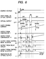
- Fig. 6 shows the variation of the external condition parameters Vs, SD, OPT, laser diode driving current IF, differential signal S7 of the constant temperature control mode, differential signal S14 of the wavelength monitoring control mode, mode signal S4 output from the control mode decision circuit 1, mode signal S3 output from the delay time circuit 3, control mode selection signal in the control mode selector circuit 2, and the wavelength lambda of the laser output light, taking the elapsed time as the horizontal axis.
- the control mode decision circuit 1 when the stop signal is ON, the output of the control mode decision circuit 1 is Low level from the equation (2), and the control mode selector circuit 2 selects the laser element constant temperature control mode which stabilizes the wavelength even when a stop signal is ON.
- the source voltage is ON, the stop signal is OFF, and the optical output is normal. Therefore the output signal S4 of the control mode decision circuit 4 is High level from the equation (2), and the control mode selector circuit 2 selects the wavelength monitoring control mode which can stabilize wavelength in the long-term, and which can compensate wavelength fluctuations due to deterioration of the laser over time.
- the optical output wavelength can be stabilized with high precision to suit external conditions.
- the laser element constant temperature control mode as high precision wavelength stabilization can be achieved in the short-term, and as the temperature control signal is unaffected by the laser output light, abnormal operation of the control circuit can be avoided when there is a large variation of laser output light due to factors other than temperature variation, such as for example when power is switched on, when a stop signal is supplied, or when there is a loss of signal due to an obstacle in the laser light detection system comprising the optical coupler 11.
- the wavelength monitoring control mode is selected, the wavelength is monitored, so wavelength variations due not only to laser element temperature variations but also to laser diode driving current variations can be stabilized with high precision in the long-term.
- the circuitry can be made compact.
- control mode can be changed over to suit the response speed of each control mode and the response characteristics of the cooling/heating element 10. Therefore, if each of these control modes has an optical wavelength stabilizing controller, plural optical transmitters having mutually different output wavelengths are provided and the outputs of these transmitters are combined into one by, for example, an optical coupler, a stable optical wavelength division multiplexer can be obtained with no inter-channel interference due to wavelength variation.
- This embodiment differs from the first embodiment in that a constant forward current control mode is provided as one control mode instead of constant temperature control.
- the control apparatus for stabilizing optical wavelength shown in Fig. 7 comprises a current deviation detector 210 which detects a deviation of laser diode driving current IF from a control target value and outputs the detected deviation as a deviation signal S16, a wavelength deviation detector 220 which detects a deviation of laser output light wavelength from a control target value and outputs the detected deviation as a deviation signal S14, a selector 230 which determines the control mode according to external conditions and selects either the deviation signal S16 from the current deviation detector 210 or the deviation signal S14 from the wavelength deviation detector 220, and a driving current controller 15 which controls the laser diode driving current IF according to the deviation signal selected by the selector 230.
- the current deviation detector 210 has a function of detecting a deviation of laser diode driving current from a predetermined control target value of laser diode forward current, and this current deviation is used for the control mode wherein the laser diode forward current is maintained constant.
- the current deviation detector 210 comprises a driving current monitor 18 for monitoring the driving current IF of the laser diode LD, a target value setting circuit 17 for setting a control target value I of laser diode driving current, and a comparator 16 for comparing a value If' of driving current monitored by the driving current monitor 18 with the target value I set by the target value setting circuit 17, and outputting a signal S16 showing the current deviation.
- the wavelength deviation detector 220 detects a deviation of the wavelength of the light output by the laser from a predetermined wavelength control target value, and this wavelength deviation is used in the wavelength monitoring control mode.
- the wavelength deviation detector 220 has an identical construction to that of the wavelength deviation detector 120 in the first embodiment described in Fig. 5, and its description will therefore be omitted here.
- the selector 230 determines the control mode according to the external conditions of the laser, selects a deviation according to this control mode, and supplies this to the driving current controller 15.
- the selector 230 has an identical construction to that of the selector 130 in the first embodiment, and its description will therefore be omitted here.
- the driving current controller 15 controls the driving current IF for driving the laser diode LD depending on the control mode selected by the selector 130.
- the driving current IF of the laser diode LD is monitored by the driving current monitor 18.
- a difference between the output value IF' from the driving current monitor 18 and the control target value I of driving current is detected by the detector 16, and the current deviation signal S16 is output.
- the driving current controller 15 the driving current value for driving the laser element LD is controlled so that the difference between the present driving current shown by the deviation signal S16 and the target value approaches 0.
- the laser diode driving current IF is maintained constant so as to coincide with the target value I, and short-term, high precision optical wavelength stabilization is achieved.
- the laser diode driving current is monitored regardless of variations of laser output light, so control is stable even when power is switched on, when a stop signal is supplied, or when there is a loss of signal due to an obstacle in the optical signal path after the coupler.
- the constant laser diode driving current control mode is applied during periods when there is a large fluctuation of laser output light, such as when power is switched on or when a stop signal is supplied, and the wavelength monitoring control mode is applied at other times, hence the optical wavelength can be stabilized with high precision under any external conditions.
- the control apparatus for stabilizing optical wavelength shown in Fig. 7 further comprises a temperature controller 250 for maintaining the laser temperature constant.
- a temperature controller 250 for maintaining the laser temperature constant.
- the constant driving current control mode when the constant driving current control mode is selected, short-term optical wavelength stabilization is achieved, and as the control signal is unrelated to the laser output light, this is effective when power is switched on, when a stop signal is supplied, or when there is an obstacle in the optical detection path.
- the wavelength monitoring control mode when the wavelength monitoring control mode is selected, the laser output is monitored, so wavelength fluctuations due to laser element temperature variations or laser diode driving current variations are suppressed, and high precision wavelength stabilization is achieved in the long-term.
- an optical wavelength division multiplexer which avoids inter-wavelength interference between adjacent channels may be constructed.
- a plurality of lasers can be installed on a common heat sink substrate, and if a common temperature controller 250 is used, the optical wavelength multiplexing transmitter can be made more compact overall. Moreover, even if heat flow blocks between heat sinks are omitted, the optical wavelength can be stabilized with high precision.
- part of the component elements of the control apparatus for stabilizing optical wavelength for example the optical wavelength detector 120 and part of the mode selector 130, may be installed on the side of the optical signal transmission system, and the remaining component elements may be installed on the side of the optical transmitter.
- the control apparatus and method according to this invention are also applicable to a modulator integrated type of laser module which includes integrated modulators for modulating light signals output from the laser diodes.
Landscapes
- Physics & Mathematics (AREA)
- Condensed Matter Physics & Semiconductors (AREA)
- General Physics & Mathematics (AREA)
- Electromagnetism (AREA)
- Optics & Photonics (AREA)
- Semiconductor Lasers (AREA)
- Optical Communication System (AREA)
Applications Claiming Priority (3)
| Application Number | Priority Date | Filing Date | Title |
|---|---|---|---|
| JP292228/97 | 1997-10-24 | ||
| JP29222897A JP4124845B2 (ja) | 1997-10-24 | 1997-10-24 | 光波長安定制御装置 |
| JP29222897 | 1997-10-24 |
Publications (3)
| Publication Number | Publication Date |
|---|---|
| EP0911928A2 true EP0911928A2 (de) | 1999-04-28 |
| EP0911928A3 EP0911928A3 (de) | 2001-10-17 |
| EP0911928B1 EP0911928B1 (de) | 2004-01-02 |
Family
ID=17779158
Family Applications (1)
| Application Number | Title | Priority Date | Filing Date |
|---|---|---|---|
| EP98119624A Expired - Lifetime EP0911928B1 (de) | 1997-10-24 | 1998-10-16 | Verfahren und Vorrichtung zur Stabilisierung optischer Wellenlängen |
Country Status (4)
| Country | Link |
|---|---|
| US (2) | US6212210B1 (de) |
| EP (1) | EP0911928B1 (de) |
| JP (1) | JP4124845B2 (de) |
| DE (1) | DE69820833D1 (de) |
Cited By (4)
| Publication number | Priority date | Publication date | Assignee | Title |
|---|---|---|---|---|
| US6501774B2 (en) | 1999-07-01 | 2002-12-31 | Fujitsu Limited | Optical transmission apparatus for multiple wavelengths and optical transmission wavelength control method |
| WO2003056736A1 (en) * | 2001-12-21 | 2003-07-10 | Redfern Broadband Networks, Inc. | Wdm add/drop multiplexer module |
| EP1608088A1 (de) * | 2004-06-16 | 2005-12-21 | OpNext Japan, Inc. | Optischer Sender und Verfahren zur Übertragung eines optischen Signals. |
| GB2599468A (en) * | 2020-10-05 | 2022-04-06 | British Telecomm | A telecommunications network |
Families Citing this family (53)
| Publication number | Priority date | Publication date | Assignee | Title |
|---|---|---|---|---|
| JP4124845B2 (ja) * | 1997-10-24 | 2008-07-23 | 日本オプネクスト株式会社 | 光波長安定制御装置 |
| JPH11163462A (ja) * | 1997-11-27 | 1999-06-18 | Hitachi Ltd | 光波長安定制御装置、光送信器、光波長多重送信器 |
| JPH11251673A (ja) * | 1998-02-27 | 1999-09-17 | Nec Corp | レーザ信号の波長制御回路 |
| JP3408426B2 (ja) * | 1998-09-02 | 2003-05-19 | 日本電気株式会社 | 光 源 |
| JP4408010B2 (ja) * | 1999-07-01 | 2010-02-03 | 富士通株式会社 | Wdm用光送信装置 |
| DE69941865D1 (de) * | 1999-08-23 | 2010-02-04 | Fujitsu Ltd | Multiplexing-Vorrichtung zur Wellenlängentrennung |
| KR100312309B1 (ko) * | 1999-11-11 | 2001-11-05 | 윤종용 | 파장 분할 다중 시스템을 위한 파장 안정화 장치 및 방법 |
| US6503268B1 (en) * | 2000-04-03 | 2003-01-07 | Ceramoptec Industries, Inc. | Therapeutic laser system operating between 1000nm and 1300nm and its use |
| US6690693B1 (en) * | 2000-05-04 | 2004-02-10 | Agility Communications, Inc. | Power and wavelength control of sampled grating distributed Bragg reflector lasers |
| CA2347551A1 (en) * | 2000-05-16 | 2001-11-16 | Furukawa Electric Co., Ltd. | Semiconductor laser apparatus |
| US7061943B2 (en) * | 2000-06-29 | 2006-06-13 | Agility Communications, Inc. | Controller calibration for small form factor sampled grating distributed Bragg reflector laser |
| US6738140B2 (en) | 2000-09-19 | 2004-05-18 | Lambda Control, Inc. | Wavelength detector and method of detecting wavelength of an optical signal |
| US6839364B1 (en) * | 2000-09-29 | 2005-01-04 | Triquint Technology Holding Co. | Feedback control loop operating system for tunable source |
| JP3851809B2 (ja) * | 2000-12-06 | 2006-11-29 | 住友電気工業株式会社 | 半導体レーザモジュール |
| JP3795762B2 (ja) * | 2001-03-16 | 2006-07-12 | エヌティティエレクトロニクス株式会社 | 光出力制御回路 |
| JP2002319736A (ja) * | 2001-04-23 | 2002-10-31 | Furukawa Electric Co Ltd:The | レーザ光の波長調整装置 |
| US6954476B2 (en) * | 2001-05-15 | 2005-10-11 | Agility Communications, Inc. | Sampled grating distributed Bragg reflector laser controller |
| JP3737383B2 (ja) * | 2001-05-21 | 2006-01-18 | ユーディナデバイス株式会社 | 半導体レーザモジュール試験装置および半導体レーザモジュール試験方法 |
| JP3629446B2 (ja) * | 2001-06-29 | 2005-03-16 | ユーディナデバイス株式会社 | 光半導体レーザの波長検査方法および装置 |
| KR100765001B1 (ko) * | 2001-07-10 | 2007-10-09 | 엘지노텔 주식회사 | 다중채널용 광파장 안정화장치 |
| US20030025966A1 (en) * | 2001-08-03 | 2003-02-06 | Ross Halgren | OSP hardened WDM network |
| DE60208416T2 (de) * | 2001-10-09 | 2006-06-22 | Infinera Corp., Sunnyvale | Digitale optische netzwerkarchitektur |
| US7116851B2 (en) | 2001-10-09 | 2006-10-03 | Infinera Corporation | Optical signal receiver, an associated photonic integrated circuit (RxPIC), and method improving performance |
| US20030076568A1 (en) * | 2001-10-22 | 2003-04-24 | Adc Telecommunications, Inc. | Light frequency stabilizer |
| US7038782B2 (en) | 2001-12-11 | 2006-05-02 | Adc Telecommunications, Inc. | Robust wavelength locker for control of laser wavelength |
| US7075656B2 (en) | 2001-12-11 | 2006-07-11 | Adc Telecommunications, Inc. | Method and algorithm for continuous wavelength locking |
| US6859469B2 (en) * | 2001-12-11 | 2005-02-22 | Adc Telecommunications, Inc. | Method and apparatus for laser wavelength stabilization |
| US6795316B2 (en) * | 2001-12-21 | 2004-09-21 | Redfern Broadband Networks, Inc. | WDM add/drop multiplexer module |
| JP2003318481A (ja) * | 2002-04-25 | 2003-11-07 | Sumitomo Electric Ind Ltd | レーザ制御回路およびレーザモジュール |
| JP3945308B2 (ja) * | 2002-05-09 | 2007-07-18 | 住友電気工業株式会社 | 光送信装置 |
| US7308008B2 (en) * | 2002-11-08 | 2007-12-11 | Finisar Corporation | Magnetically controlled heat sink |
| US8891184B2 (en) * | 2003-05-21 | 2014-11-18 | Techelan, Llc | Method and apparatus for optically-enhanced cooling |
| US7321606B2 (en) * | 2003-10-09 | 2008-01-22 | National Semiconductor Corporation | Laser trim and compensation methodology for passively aligning optical transmitter |
| US7433375B2 (en) * | 2003-10-09 | 2008-10-07 | National Semiconductor Corporation | Laser trim and compensation methodology for passively aligning optical transmitter |
| US7539416B2 (en) * | 2003-12-09 | 2009-05-26 | Electronics And Telecommunications Research Institute | Optical network terminal and wavelength division multiplexing based optical network having the same |
| US6998587B2 (en) * | 2003-12-18 | 2006-02-14 | Intel Corporation | Apparatus and method for heating micro-components mounted on a substrate |
| US20050180711A1 (en) * | 2004-02-13 | 2005-08-18 | Kamath Kishore K. | Dual loop automatic power control of optical transmitters |
| US20050271096A1 (en) * | 2004-04-12 | 2005-12-08 | Rolland Zeleny | Laser output temperature compensation |
| KR100609387B1 (ko) | 2004-12-20 | 2006-08-08 | 한국전자통신연구원 | 광통신용 광원의 파장 안정화 장치 |
| JP5328159B2 (ja) | 2005-03-01 | 2013-10-30 | セルカコア・ラボラトリーズ・インコーポレーテッド | 多波長センサ発光体 |
| US20070003285A1 (en) * | 2005-06-30 | 2007-01-04 | Meyer A D | Optical signal source wavelength stabilization system and method |
| JP5011914B2 (ja) * | 2006-09-28 | 2012-08-29 | 住友電気工業株式会社 | レーザダイオード制御装置及びatc回路の駆動方法 |
| CN101175352B (zh) * | 2007-09-04 | 2011-03-30 | 浙江大学 | 超辐射发光二极管的数控驱动方法及其装置 |
| US20100004518A1 (en) | 2008-07-03 | 2010-01-07 | Masimo Laboratories, Inc. | Heat sink for noninvasive medical sensor |
| US8630691B2 (en) | 2008-08-04 | 2014-01-14 | Cercacor Laboratories, Inc. | Multi-stream sensor front ends for noninvasive measurement of blood constituents |
| US8339584B2 (en) | 2010-05-21 | 2012-12-25 | Teledyne Technologies Incorporated | Velocity measuring system |
| US20120300040A1 (en) * | 2011-05-25 | 2012-11-29 | Microsoft Corporation | Imaging system |
| US20180041007A1 (en) * | 2015-05-27 | 2018-02-08 | Mitsubishi Electric Corporation | Temperature control circuit, transmitter, and temperature control method |
| US9660114B2 (en) * | 2015-06-25 | 2017-05-23 | International Business Machines Corporation | Temperature stabilization of an on-chip temperature-sensitive element |
| US11114809B2 (en) | 2018-02-22 | 2021-09-07 | Lumentum Operations Llc | Fiber optic device operational monitoring |
| KR20220129033A (ko) | 2020-01-13 | 2022-09-22 | 마시모 코오퍼레이션 | 생리학적 파라미터 모니터링 기능이 있는 웨어러블 디바이스 |
| CN112965188A (zh) * | 2021-03-23 | 2021-06-15 | 成都优博创通信技术有限公司 | 一种激光器加热组件以及光模块 |
| EP4370022A1 (de) | 2021-07-13 | 2024-05-22 | Masimo Corporation | Tragbare vorrichtung mit überwachung physiologischer parameter |
Family Cites Families (14)
| Publication number | Priority date | Publication date | Assignee | Title |
|---|---|---|---|---|
| JPS57186383A (en) | 1981-05-13 | 1982-11-16 | Hitachi Ltd | Semiconductor laser device |
| US4583228A (en) * | 1983-11-21 | 1986-04-15 | At&T Bell Laboratories | Frequency stabilization of lasers |
| DE3590327T1 (de) * | 1984-07-05 | 1986-06-26 | Ricoh Co., Ltd., Tokio/Tokyo | Verfahren zum Regeln der Temperatur eines Halbleiterlasers in einer optischen Abtasteinrichtung |
| DE3542090A1 (de) * | 1985-11-28 | 1987-07-23 | Standard Elektrik Lorenz Ag | Verfahren und schaltung zur automatischen inbetriebnahme eines wellenlaengenstabilisierten halbleiterlasers |
| JPH01238083A (ja) * | 1988-03-18 | 1989-09-22 | Nkk Corp | 半導体レーザの発振波長安定方法 |
| US5299212A (en) * | 1993-03-10 | 1994-03-29 | At&T Bell Laboratories | Article comprising a wavelength-stabilized semiconductor laser |
| JP3184359B2 (ja) * | 1993-03-19 | 2001-07-09 | 富士通株式会社 | 半導体レーザ制御方法および半導体レーザ制御装置 |
| EP0618653B1 (de) * | 1993-03-30 | 1997-07-16 | Nec Corporation | Frequenzstabilisationsverfahren für Halbleiterlaser und frequenzstabilisierte Lichtquelle |
| GB9308519D0 (en) * | 1993-04-24 | 1993-06-09 | Renishaw Transducer Syst | Frequency stabilised laser diode |
| US5684590A (en) * | 1995-12-29 | 1997-11-04 | Honeywell Inc. | Fiber optic gyroscope source wavelength control |
| JP4124845B2 (ja) * | 1997-10-24 | 2008-07-23 | 日本オプネクスト株式会社 | 光波長安定制御装置 |
| US6018536A (en) * | 1998-11-20 | 2000-01-25 | Sarnoff Corporation | Multiple-wavelength mode-locked laser |
| JP2000151011A (ja) * | 1998-11-13 | 2000-05-30 | Toyo Commun Equip Co Ltd | デジタル光信号送信機 |
| US6389046B1 (en) * | 1999-04-12 | 2002-05-14 | Agere Systems Guardian Corp. | Method to sense laser array power and wavelength and reduce drift for wavelength selection and stabilization |
-
1997
- 1997-10-24 JP JP29222897A patent/JP4124845B2/ja not_active Expired - Lifetime
-
1998
- 1998-10-16 DE DE69820833T patent/DE69820833D1/de not_active Expired - Lifetime
- 1998-10-16 EP EP98119624A patent/EP0911928B1/de not_active Expired - Lifetime
- 1998-10-21 US US09/176,579 patent/US6212210B1/en not_active Expired - Lifetime
-
2001
- 2001-01-25 US US09/769,915 patent/US6891867B2/en not_active Expired - Lifetime
Cited By (4)
| Publication number | Priority date | Publication date | Assignee | Title |
|---|---|---|---|---|
| US6501774B2 (en) | 1999-07-01 | 2002-12-31 | Fujitsu Limited | Optical transmission apparatus for multiple wavelengths and optical transmission wavelength control method |
| WO2003056736A1 (en) * | 2001-12-21 | 2003-07-10 | Redfern Broadband Networks, Inc. | Wdm add/drop multiplexer module |
| EP1608088A1 (de) * | 2004-06-16 | 2005-12-21 | OpNext Japan, Inc. | Optischer Sender und Verfahren zur Übertragung eines optischen Signals. |
| GB2599468A (en) * | 2020-10-05 | 2022-04-06 | British Telecomm | A telecommunications network |
Also Published As
| Publication number | Publication date |
|---|---|
| US20010021207A1 (en) | 2001-09-13 |
| EP0911928B1 (de) | 2004-01-02 |
| JP4124845B2 (ja) | 2008-07-23 |
| US6891867B2 (en) | 2005-05-10 |
| US6212210B1 (en) | 2001-04-03 |
| EP0911928A3 (de) | 2001-10-17 |
| DE69820833D1 (de) | 2004-02-05 |
| JPH11126940A (ja) | 1999-05-11 |
Similar Documents
| Publication | Publication Date | Title |
|---|---|---|
| US6212210B1 (en) | Control method and apparatus for stabilizing optical wavelength | |
| KR100315705B1 (ko) | 파장분할다중광전송시스템의파장안정화장치 | |
| US5781572A (en) | Optical wavelength stabilizing system | |
| US6483625B2 (en) | WDM optical transmission apparatus | |
| EP0920095A2 (de) | Vorrichtung zur Stabilitätskontrolle der optischen Wellenlänge und optischer Sender | |
| US5875273A (en) | Laser wavelength control under direct modulation | |
| JPWO2001003350A1 (ja) | Wdm用光送信装置 | |
| JP2962211B2 (ja) | 光送信装置 | |
| US20060159141A1 (en) | Optical transmitting module operable in wide temperature range | |
| JP2000323785A (ja) | 半導体レーザモジュールの制御装置及びその制御方法 | |
| JP2001007438A (ja) | 光送信器とこの光送信器を用いた波長多重光伝送装置 | |
| US6693932B2 (en) | Optical wavelength stabilization circuit, optical transmitter and optical transmission system | |
| US6947457B2 (en) | DFB laser driving device, DFB laser driving method and storage medium | |
| JPH0993194A (ja) | 波長安定回路 | |
| US6522675B1 (en) | Wavelength control circuit and wavelength control method of light emitting device | |
| US6452953B1 (en) | Light source | |
| JP4109977B2 (ja) | 光波長多重送信器 | |
| JP2006005042A (ja) | 光送信器および光送信方法 | |
| JP2003298524A (ja) | 波長安定化光源および発光素子のスタートアップ制御方法 | |
| US11309985B2 (en) | Light source device that includes a plurality of light sources with different wavelengths and method of controlling wavelengths | |
| JPH11251674A (ja) | 光送信器、及び光送信器における光出力及び波長の制御方法 | |
| JP2002368693A (ja) | 光送信器 | |
| JP2830794B2 (ja) | 光送信回路 | |
| KR19980084453A (ko) | 파장분할다중(wdm)방식에서 파장 안정화부를 가지는 송신장치 및 구현방법 | |
| KR20020017285A (ko) | 파장분할다중 시스템을 위한 채널 안정화 장치 및 방법 |
Legal Events
| Date | Code | Title | Description |
|---|---|---|---|
| PUAI | Public reference made under article 153(3) epc to a published international application that has entered the european phase |
Free format text: ORIGINAL CODE: 0009012 |
|
| AK | Designated contracting states |
Kind code of ref document: A2 Designated state(s): AT BE CH CY DE DK ES FI FR GB GR IE IT LI LU MC NL PT SE Kind code of ref document: A2 Designated state(s): DE FR GB IT |
|
| AX | Request for extension of the european patent |
Free format text: AL;LT;LV;MK;RO;SI |
|
| RAP1 | Party data changed (applicant data changed or rights of an application transferred) |
Owner name: OPNEXT JAPAN, INC. |
|
| PUAL | Search report despatched |
Free format text: ORIGINAL CODE: 0009013 |
|
| AK | Designated contracting states |
Kind code of ref document: A3 Designated state(s): AT BE CH CY DE DK ES FI FR GB GR IE IT LI LU MC NL PT SE |
|
| AX | Request for extension of the european patent |
Free format text: AL;LT;LV;MK;RO;SI |
|
| RIC1 | Information provided on ipc code assigned before grant |
Free format text: 7H 01S 3/133 A, 7H 01S 5/068 B, 7H 01S 5/0687 B, 7H 01S 5/0683 B |
|
| 17P | Request for examination filed |
Effective date: 20020410 |
|
| AKX | Designation fees paid |
Free format text: DE FR GB IT |
|
| 17Q | First examination report despatched |
Effective date: 20020719 |
|
| GRAH | Despatch of communication of intention to grant a patent |
Free format text: ORIGINAL CODE: EPIDOS IGRA |
|
| RIC1 | Information provided on ipc code assigned before grant |
Ipc: 7H 01S 5/0683 B Ipc: 7H 01S 5/0687 B Ipc: 7H 01S 5/068 A |
|
| GRAS | Grant fee paid |
Free format text: ORIGINAL CODE: EPIDOSNIGR3 |
|
| GRAA | (expected) grant |
Free format text: ORIGINAL CODE: 0009210 |
|
| AK | Designated contracting states |
Kind code of ref document: B1 Designated state(s): DE FR GB IT |
|
| PG25 | Lapsed in a contracting state [announced via postgrant information from national office to epo] |
Ref country code: IT Free format text: LAPSE BECAUSE OF FAILURE TO SUBMIT A TRANSLATION OF THE DESCRIPTION OR TO PAY THE FEE WITHIN THE PRESCRIBED TIME-LIMIT;WARNING: LAPSES OF ITALIAN PATENTS WITH EFFECTIVE DATE BEFORE 2007 MAY HAVE OCCURRED AT ANY TIME BEFORE 2007. THE CORRECT EFFECTIVE DATE MAY BE DIFFERENT FROM THE ONE RECORDED. Effective date: 20040102 |
|
| REG | Reference to a national code |
Ref country code: GB Ref legal event code: FG4D |
|
| REF | Corresponds to: |
Ref document number: 69820833 Country of ref document: DE Date of ref document: 20040205 Kind code of ref document: P |
|
| PG25 | Lapsed in a contracting state [announced via postgrant information from national office to epo] |
Ref country code: DE Free format text: LAPSE BECAUSE OF FAILURE TO SUBMIT A TRANSLATION OF THE DESCRIPTION OR TO PAY THE FEE WITHIN THE PRESCRIBED TIME-LIMIT Effective date: 20040403 |
|
| ET | Fr: translation filed | ||
| PLBE | No opposition filed within time limit |
Free format text: ORIGINAL CODE: 0009261 |
|
| STAA | Information on the status of an ep patent application or granted ep patent |
Free format text: STATUS: NO OPPOSITION FILED WITHIN TIME LIMIT |
|
| 26N | No opposition filed |
Effective date: 20041005 |
|
| REG | Reference to a national code |
Ref country code: FR Ref legal event code: CD Owner name: OCLARO JAPAN, INC., JP Effective date: 20150424 Ref country code: FR Ref legal event code: CA Effective date: 20150424 |
|
| REG | Reference to a national code |
Ref country code: FR Ref legal event code: PLFP Year of fee payment: 19 |
|
| REG | Reference to a national code |
Ref country code: FR Ref legal event code: PLFP Year of fee payment: 20 |
|
| PGFP | Annual fee paid to national office [announced via postgrant information from national office to epo] |
Ref country code: FR Payment date: 20170918 Year of fee payment: 20 |
|
| PGFP | Annual fee paid to national office [announced via postgrant information from national office to epo] |
Ref country code: GB Payment date: 20171011 Year of fee payment: 20 |
|
| REG | Reference to a national code |
Ref country code: GB Ref legal event code: PE20 Expiry date: 20181015 |
|
| PG25 | Lapsed in a contracting state [announced via postgrant information from national office to epo] |
Ref country code: GB Free format text: LAPSE BECAUSE OF EXPIRATION OF PROTECTION Effective date: 20181015 |