EP0920095A2 - Vorrichtung zur Stabilitätskontrolle der optischen Wellenlänge und optischer Sender - Google Patents
Vorrichtung zur Stabilitätskontrolle der optischen Wellenlänge und optischer Sender Download PDFInfo
- Publication number
- EP0920095A2 EP0920095A2 EP98121983A EP98121983A EP0920095A2 EP 0920095 A2 EP0920095 A2 EP 0920095A2 EP 98121983 A EP98121983 A EP 98121983A EP 98121983 A EP98121983 A EP 98121983A EP 0920095 A2 EP0920095 A2 EP 0920095A2
- Authority
- EP
- European Patent Office
- Prior art keywords
- laser diode
- drive current
- value
- temperature
- diode drive
- Prior art date
- Legal status (The legal status is an assumption and is not a legal conclusion. Google has not performed a legal analysis and makes no representation as to the accuracy of the status listed.)
- Withdrawn
Links
Images

Classifications
-
- H—ELECTRICITY
- H01—ELECTRIC ELEMENTS
- H01S—DEVICES USING THE PROCESS OF LIGHT AMPLIFICATION BY STIMULATED EMISSION OF RADIATION [LASER] TO AMPLIFY OR GENERATE LIGHT; DEVICES USING STIMULATED EMISSION OF ELECTROMAGNETIC RADIATION IN WAVE RANGES OTHER THAN OPTICAL
- H01S5/00—Semiconductor lasers
- H01S5/06—Arrangements for controlling the laser output parameters, e.g. by operating on the active medium
- H01S5/068—Stabilisation of laser output parameters
- H01S5/06808—Stabilisation of laser output parameters by monitoring the electrical laser parameters, e.g. voltage or current
-
- H—ELECTRICITY
- H01—ELECTRIC ELEMENTS
- H01S—DEVICES USING THE PROCESS OF LIGHT AMPLIFICATION BY STIMULATED EMISSION OF RADIATION [LASER] TO AMPLIFY OR GENERATE LIGHT; DEVICES USING STIMULATED EMISSION OF ELECTROMAGNETIC RADIATION IN WAVE RANGES OTHER THAN OPTICAL
- H01S5/00—Semiconductor lasers
- H01S5/06—Arrangements for controlling the laser output parameters, e.g. by operating on the active medium
- H01S5/068—Stabilisation of laser output parameters
- H01S5/0683—Stabilisation of laser output parameters by monitoring the optical output parameters
- H01S5/0687—Stabilising the frequency of the laser
-
- H—ELECTRICITY
- H01—ELECTRIC ELEMENTS
- H01S—DEVICES USING THE PROCESS OF LIGHT AMPLIFICATION BY STIMULATED EMISSION OF RADIATION [LASER] TO AMPLIFY OR GENERATE LIGHT; DEVICES USING STIMULATED EMISSION OF ELECTROMAGNETIC RADIATION IN WAVE RANGES OTHER THAN OPTICAL
- H01S5/00—Semiconductor lasers
- H01S5/0014—Measuring characteristics or properties thereof
- H01S5/0035—Simulations of laser characteristics
-
- H—ELECTRICITY
- H01—ELECTRIC ELEMENTS
- H01S—DEVICES USING THE PROCESS OF LIGHT AMPLIFICATION BY STIMULATED EMISSION OF RADIATION [LASER] TO AMPLIFY OR GENERATE LIGHT; DEVICES USING STIMULATED EMISSION OF ELECTROMAGNETIC RADIATION IN WAVE RANGES OTHER THAN OPTICAL
- H01S5/00—Semiconductor lasers
- H01S5/02—Structural details or components not essential to laser action
- H01S5/024—Arrangements for thermal management
- H01S5/02407—Active cooling, e.g. the laser temperature is controlled by a thermo-electric cooler or water cooling
- H01S5/02415—Active cooling, e.g. the laser temperature is controlled by a thermo-electric cooler or water cooling by using a thermo-electric cooler [TEC], e.g. Peltier element
-
- H—ELECTRICITY
- H01—ELECTRIC ELEMENTS
- H01S—DEVICES USING THE PROCESS OF LIGHT AMPLIFICATION BY STIMULATED EMISSION OF RADIATION [LASER] TO AMPLIFY OR GENERATE LIGHT; DEVICES USING STIMULATED EMISSION OF ELECTROMAGNETIC RADIATION IN WAVE RANGES OTHER THAN OPTICAL
- H01S5/00—Semiconductor lasers
- H01S5/06—Arrangements for controlling the laser output parameters, e.g. by operating on the active medium
- H01S5/0607—Arrangements for controlling the laser output parameters, e.g. by operating on the active medium by varying physical parameters other than the potential of the electrodes, e.g. by an electric or magnetic field, mechanical deformation, pressure, light, temperature
- H01S5/0612—Arrangements for controlling the laser output parameters, e.g. by operating on the active medium by varying physical parameters other than the potential of the electrodes, e.g. by an electric or magnetic field, mechanical deformation, pressure, light, temperature controlled by temperature
Definitions
- the present invention relates to an optical wavelength stability control apparatus for stabilizing an optical wavelength output from a laser diode (hereinafter, LD).
- the present invention relates to an optical wavelength stability control apparatus suitable for an optical multiple wavelength transmission.
- an optical communication system to which an optical signal is transmitted by using an optical fiber requires an enlarged transmission capacity.
- the optical multiple wavelength transmission is implemented to realize an increase in transmission capacity.
- a plurality of channels are transmitted through a common transmission path by assigning respective signals to different optical wavelengths.
- the precision stabilization of the optical wavelength within ⁇ 0.2 nm has long been required so that adjacent wavelengths do not interfere with each other.
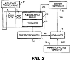
- FIG. 2 illustrates a conventional apparatus for optical wavelength stabilization.
- a temperature fluctuation as well as a drive current fluctuation of a semiconductor laser cause a fluctuation of the optical transmitter.
- FIG. 2 illustrates an apparatus used for stabilizing an optical wavelength by keeping the temperature of a semiconductor laser 5 constant.
- a temperature monitor 10 detects the temperature of LD using a thermistor 9 and a reference voltage generator 3b outputs a reference temperature voltage which is a target value for controlling a temperature.
- An output voltage (Vth) of the temperature monitor 10 and an output voltage (Vref1) of the reference voltage generator 3b are compared at a comparator 8, and the difference between Vth and Vref1 is calculated.
- the stabilization of the optical wavelength is done by determining a drive current value of a thermoelectric cooler 12 so that an output value at the comparator 8 becomes zero.
- a semiconductor laser apparatus described in a Japanese laid-open patent No 57-186383 also employs the same method.
- the electric power consumption (an input electric power to the semiconductor laser) required to obtain the identical optical power output gradually increases over time with the age of a semiconductor laser.
- the temperature at an active layer of the semiconductor laser rises and thereby causes an optical wavelength to fluctuate.
- Japanese laid open patent 6-283797 describes a control method for keeping an optical power output and the temperature of the active layer constant. According to this method the temperature of a heat sink is controlled to negate a temperature rise of the active layer caused by an increase of the electric power consumption to gain an identical optical power with respect to an age related change of the semiconductor laser. Based upon this control, the temperature of the laser can be constantly controlled for a long period of time.
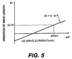
- the LD drive current is controlled by an auto power control circuit (hereinafter, APC) so that the optical output of the LD becomes constant. Therefore, as shown in FIG. 4, the LD drive current value If (t) increases.
- APC auto power control circuit
- ⁇ ⁇ ⁇ ⁇ If(tn)-If(t0) ⁇ +(Vth-Vref1) ⁇ ⁇ ⁇ ⁇
- An object of the present invention is to provide an optical wavelength stability control apparatus for stabilizing the wavelength precisely by compensating for the wavelength drift over a long period of time.
- An object of the present invention is to provide an optical wavelength stability control apparatus for stabilizing the optical wavelength output from a LD.
- This apparatus includes a current detector for detecting the LD drive current driving the LD, and a thermal controller including a compensated reference voltage generator 3a, a comparator 8, a thermistor 9, a temperature monitor 10, a current controller 11 and a thermoelectric cooler 12, for controlling a temperature of the LD to be a control target value.
- the thermal controller includes a reference generator means for setting the control target value in response to the LD drive current detected by the current detector.
- Another object of the present invention is to provide an optical transmitter including a plurality of optical wavelength stability control apparatus, each of the optical wavelength stability control apparatus including a laser diode module having the LD, a photo-diode (hereinafter, PD), a thermoelectric cooler and a thermistor built-in.
- the apparatus includes an APC capable of controlling the stability of the optical power output by varying the LD drive current driving the LD,
- Yet another object of the present invention is to provide a method for stabilizing an optical wavelength output from a LD using a leading discharge at a diode connection portion.
- the method encompasses detecting a fluctuation of a drive current driving a LD and regulating a temperature at a diode connection portion to compensate the fluctuation of an optical wavelength along with a variation of the LD drive current.
- Still another object is to provide an optical multiple wavelength transmitter for transmitting light having a plurality of different wavelengths.
- the transmitter includes a plurality of optical wavelength stability control apparatus, each of which includes:
- the transmitter may include a plurality of laser diode modules and a common current detector and a common means for controlling the temperatures of the laser diodes.
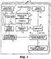
- FIG. 1 shows an example of a plurality of optical wavelength stability control apparatuses 110 used in an optical transmitter.
- Each of the apparatus includes a laser diode module 100 having a LD 5, a PD 6, a thermoelectric cooler 12 and a thermistor 9, a APC 7, a LD drive current detector 1, a LD drive current increase/decrease normalization unit 2, a compensated reference voltage generator 3a, a current-wavelength conversion coefficient decider 4, a comparator 8, a temperature monitor 10 and a current controller 11.
- a plurality of such apparatuses are used to form the optical transmitter.
- Each of the apparatuses has a LD outputting a respective optical wavelength. While FIG. 1 illustrates an embodiment where each apparatus 110 is provided with a plurality of elements as shown, according to another embodiment, the transmitter may only have a plurality of laser diode modules, while the remaining elements are commonly provided.
- thermoelectric cooler 12 controls the temperature of the laser diode to be a control target value.
- the thermal controller includes thermoelectric cooler 12, thermistor 9, temperature monitor 10, comparator 8, compensated reference voltage generator 3a, current-wavelength conversion coefficient decider 4 and current controller 11.
- thermoelectric cooler 12 includes thermoelectric cooler 12, thermistor 9, temperature monitor 10, comparator 8, compensated reference voltage generator 3a, current-wavelength conversion coefficient decider 4 and current controller 11.
- the PD 6 is used to detect an intensity of an optical power from the LD.
- thermoelectric cooler 12 is used to cool the LD 5 by discharging heat from the LD 5 to outside of the laser diode module 100. On the other hand, the thermoelectric cooler 12 transfers heat in the reverse direction, thereby causing the LD 5 to absorb heat from outside of the module 100.
- a portion of light outputted from the LD 5 is branched to the PD 6 and an intensity of the optical power is detected.
- the APC 7 controls the drive current value so that the power output value detected by the PD 6 becomes a constant.
- the detected power output is proportional to the optical output power of the LD 5 because the optical power output is branched at a constant ratio. Accordingly, the optical output power from the LD 5 is stabilized by controlling the drive current value.
- the LD drive current increase / decrease normalization unit 2 normalizes a deviation of the drive current from an initial value, and outputs such deviation as a standard value. This standard value is input to the compensated reference voltage generator 3a.
- the compensated reference voltage generator 3a generates a temperature setting value correcting an optical wavelength drift due to deterioration caused by aging of the LD, based upon an input standard value and a current-wavelength conversion coefficient ⁇ input from a current-wavelength conversion coefficient decider 4.
- the temperature setting value (Vatc) is output to the comparator 8.
- the comparator 8 detects a difference between the temperature setting value from the compensated reference voltage generator 3a and a temperature of the LD detected by the thermistor 9.
- the current controller 11 determines the current value for driving the thermoelectric cooler 12 so that the difference detected by the comparator 8 becomes small (even zero, for example) thereby controlling the stability of an optical wavelength of the LD 5.
- An optical wavelength stability control apparatus increases the LD drive current with the APC 7 so as to keep the optical power output constant when the LD 5 deteriorates.
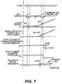
- An increased quantity of the LD drive current is detected for every (Tx+Ty) seconds, output as a normalized value, If (tn) - If (t0) via the LD drive current detector 1 and the LD drive current increase / decrease normalization unit 2.
- the compensated reference voltage generator 3a calculates a voltage Vref2 to correct an optical wavelength drift share based on the normalized increased value of the drive current and the current -wavelength conversion coefficient ⁇ .
- the voltage generator 3a outputs the compensated reference voltage Vref1 - Vref2 to the comparator 8.
- the comparator 8 compares the detected temperature of the LD (Vth) with the compensated reference voltage (Vref1-Vref2) and outputs the difference value as a comparison value (Vatc).
- the comparison value (Vatc) is a temperature setting value.
- the current controller 11 controls a current value (Iatc) applied to the thermoelectric cooler 12 to regulate the comparison value (Vatc) to be zero.
- optical wavelength stability control is given by using the following equations.
- ⁇ ' ⁇ ⁇ ⁇ If(tn)-If(t0) ⁇ +(1/G) ⁇ Vatc ⁇ ⁇ ⁇ ⁇
- Vref2 the compensated optical wavelength drift voltage (compensated temperature)
- the compensated reference voltage generator 3a calculates Vref2 according to equation 8.
- equation 6 can be represented as equation 9.
- ⁇ ' ( Vth -Vref1) ⁇ ⁇ ⁇ ⁇
- equation 9 is compared with the aforementioned equation 5 that is the wavelength drift share in the conventional method, the wavelength drift share causing the LD drive current increase/decrease of ⁇ ⁇ ⁇ If(tn) - If(t0) ⁇ can be removed and it is possible to precisely stabilize the optical wavelength.
- ⁇ , ⁇ are specific values of the LD determined for the respective controlled LD.
- ⁇ is a value determined for the control system and has a different value depending on the control system.
- the detection of the LD drive current value in the LD drive current detector 1 can be made discretely. By discretely detecting, a control instability factor that two loops exist in the control system can be eliminated.
- the waiting time Ty is long enough, then the stability of a control system can be increased. However, if the time Ty is made long, the maximum drift error of the optical wavelength value ⁇ max becomes large.
- a periodical detection can be done by setting a predicted period during which the variation of the drive current requiring a change of setting temperature will occur due to aging of the LD.
- a dynamic period can be prescribed such that the detection interval is made short in accordance with an increase of the previously detected change in drive current and long in accordance with a decrease of the previously detected change in the drive current.
- the discrete sampling of the LD drive current is achieved by synchronizing the compensated reference voltage generator 3a as shown in FIG. 1 with a microcomputer using a clock frequency.
- the compensated reference voltage generator 3a capable of discretely sampling the LD drive current can be simply configured.
- a mean value detection can be done at a sampling time Tx.
- a deterioration of the precision control caused by sudden noises such as a power surge onto the LD drive current value can be prevented.
- the LD drive current detector 1 shown in FIG. 1 can detect the LD drive current value discretely and perform the mean value detection at the sampling time Tx. As a result, it is possible to delete two loops causing the control instability factor in the control system and to reduce an influence of the moment noise to the detected LD drive current value. Accordingly, the stability of the control system can be improved.
- the LD drive current value driving the LD is detected and the setting temperature can be set in accordance with the fluctuation of the LD drive current value.
- the setting temperature can be set in accordance with the fluctuation of the LD drive current value.
- control instability factor caused by two loops existing in the control system can be eliminated by detecting the LD drive current value discretely.
Landscapes
- Physics & Mathematics (AREA)
- Condensed Matter Physics & Semiconductors (AREA)
- General Physics & Mathematics (AREA)
- Electromagnetism (AREA)
- Optics & Photonics (AREA)
- Semiconductor Lasers (AREA)
Applications Claiming Priority (3)
| Application Number | Priority Date | Filing Date | Title |
|---|---|---|---|
| JP32634197 | 1997-11-27 | ||
| JP326341/97 | 1997-11-27 | ||
| JP9326341A JPH11163462A (ja) | 1997-11-27 | 1997-11-27 | 光波長安定制御装置、光送信器、光波長多重送信器 |
Publications (2)
| Publication Number | Publication Date |
|---|---|
| EP0920095A2 true EP0920095A2 (de) | 1999-06-02 |
| EP0920095A3 EP0920095A3 (de) | 2002-05-29 |
Family
ID=18186709
Family Applications (1)
| Application Number | Title | Priority Date | Filing Date |
|---|---|---|---|
| EP98121983A Withdrawn EP0920095A3 (de) | 1997-11-27 | 1998-11-19 | Vorrichtung zur Stabilitätskontrolle der optischen Wellenlänge und optischer Sender |
Country Status (3)
| Country | Link |
|---|---|
| US (1) | US6229832B1 (de) |
| EP (1) | EP0920095A3 (de) |
| JP (1) | JPH11163462A (de) |
Cited By (6)
| Publication number | Priority date | Publication date | Assignee | Title |
|---|---|---|---|---|
| EP0926789B1 (de) * | 1997-12-24 | 2002-06-05 | Nortel Networks Limited | Lasermodul mit gleichzeitiger Steuerung der Wellenlänge und Ausgangsleistung |
| EP1289083A1 (de) * | 2001-08-28 | 2003-03-05 | The Furukawa Electric Co., Ltd. | DFB-Laseranordnung und Lasermodul |
| EP1109335A3 (de) * | 1999-12-15 | 2003-03-12 | Agere Systems Optoelectronics Guardian Corporation | Verfahren zur Sicherung von korrekter Kanalselektion in einem Wellenlängenstabilisierten Steureungssystem |
| EP1255332A3 (de) * | 2001-04-16 | 2003-12-03 | The Furukawa Electric Co., Ltd. | Halbleiterlaservorrichtung und Treiberkontrollverfahren für eine Halbleiterlaservorrichtung |
| EP2058907A1 (de) * | 2007-11-06 | 2009-05-13 | Mitutoyo Corporation | Frequenzstabilisierte Laservorrichtung, Laserfrequenzstabilisierungsverfahren und Laserfrequenzstabilisierungsprogramm |
| EP2043208A3 (de) * | 2005-03-16 | 2009-12-09 | Nippon Telegraph and Telephone Corporation | Optische Kommunikationslichtquelleneinheit und Wellenlängenüberwachungssteuerverfahren |
Families Citing this family (30)
| Publication number | Priority date | Publication date | Assignee | Title |
|---|---|---|---|---|
| JPH11220199A (ja) * | 1998-01-30 | 1999-08-10 | Ando Electric Co Ltd | 波長可変光源装置 |
| WO2000069039A1 (en) * | 1999-05-10 | 2000-11-16 | Kvh Industries, Inc. | Broadening the linewidth of a semiconductor laser |
| JP4408010B2 (ja) * | 1999-07-01 | 2010-02-03 | 富士通株式会社 | Wdm用光送信装置 |
| JP4103287B2 (ja) * | 2000-02-14 | 2008-06-18 | 横河電機株式会社 | Dfbレーザ駆動装置、dfbレーザ駆動方法、及び記憶媒体 |
| US7120119B2 (en) * | 2000-06-08 | 2006-10-10 | International Business Machines Corporation | Management of protocol information in PNNI hierarchical networks |
| JP3795762B2 (ja) * | 2001-03-16 | 2006-07-12 | エヌティティエレクトロニクス株式会社 | 光出力制御回路 |
| JP3737383B2 (ja) * | 2001-05-21 | 2006-01-18 | ユーディナデバイス株式会社 | 半導体レーザモジュール試験装置および半導体レーザモジュール試験方法 |
| AU2002319756A1 (en) * | 2001-08-03 | 2003-02-17 | Photon-X, Inc. | System and method for the electronic control of a laser diode and thermoelectric cooler |
| US6697397B2 (en) * | 2001-11-15 | 2004-02-24 | Alcatel | Wavelength compensated ALC loop |
| JP3945308B2 (ja) * | 2002-05-09 | 2007-07-18 | 住友電気工業株式会社 | 光送信装置 |
| JP3810008B2 (ja) * | 2002-07-09 | 2006-08-16 | ユーディナデバイス株式会社 | 光通信モジュール、波長ロッカーモジュール、その設定値取得装置及び設定値取得方法、並びにそのプログラム及びそのプログラムを記録した記録媒体 |
| US6917635B2 (en) * | 2002-09-30 | 2005-07-12 | Anthony Stanley Pruszenski, Jr. | Producing radiation of a desired frequency with multiple sources |
| US6922423B2 (en) * | 2003-04-11 | 2005-07-26 | Robert L. Thornton | Control system for a semiconductor laser |
| US7266136B2 (en) * | 2004-03-25 | 2007-09-04 | Finisar Corporation | Temperature compensation for fiber optic transceivers using optimized convergence algorithms |
| JP2006114774A (ja) * | 2004-10-15 | 2006-04-27 | Mitsubishi Electric Corp | 波長安定化半導体レーザ装置 |
| JP2007329212A (ja) * | 2006-06-07 | 2007-12-20 | Opnext Japan Inc | 光送信器および光送信方法 |
| JP4712658B2 (ja) * | 2006-09-22 | 2011-06-29 | 古河電気工業株式会社 | 半導体レーザモジュール |
| JP4983312B2 (ja) * | 2007-02-28 | 2012-07-25 | 住友電気工業株式会社 | 光送信モジュール及びその出射光の波長変化又は劣化を検知する方法 |
| US7505492B2 (en) * | 2007-05-11 | 2009-03-17 | Corning Incorporated | Alignment of lasing wavelength with wavelength conversion peak using modulated wavelength control signal |
| US8204091B2 (en) * | 2008-07-03 | 2012-06-19 | Corning Incorporated | Wavelength normalization in phase section of semiconductor lasers |
| JP2010051503A (ja) * | 2008-08-28 | 2010-03-11 | Sharp Corp | 撮像装置 |
| JP5473451B2 (ja) * | 2009-07-24 | 2014-04-16 | 三菱電機株式会社 | 光送信器、安定化光源およびレーザダイオードの制御方法 |
| US9279723B2 (en) | 2010-08-19 | 2016-03-08 | Novatrans Group Sa | Terahertz spectroscopy system and method |
| US20180041007A1 (en) * | 2015-05-27 | 2018-02-08 | Mitsubishi Electric Corporation | Temperature control circuit, transmitter, and temperature control method |
| JP6115609B2 (ja) * | 2015-10-07 | 2017-04-19 | ウシオ電機株式会社 | レーザ光源装置 |
| WO2018123122A1 (ja) * | 2016-12-28 | 2018-07-05 | 住友電気工業株式会社 | 光送信器、光トランシーバおよび光送信器の製造方法 |
| WO2018158837A1 (ja) * | 2017-02-28 | 2018-09-07 | パイオニア株式会社 | 温度制御装置、温度制御方法、コンピュータプログラム及び記憶媒体 |
| JP7175264B2 (ja) * | 2017-03-31 | 2022-11-18 | 三菱電機株式会社 | 光送信機 |
| JP2019149400A (ja) * | 2018-02-26 | 2019-09-05 | 株式会社ミツトヨ | レーザ光源装置及びレーザ光調整方法 |
| CN115275774B (zh) * | 2022-09-29 | 2022-12-16 | 南京旭奥科技有限公司 | 一种在tdlas应用中半导体激光器的波长控制方法及系统 |
Family Cites Families (15)
| Publication number | Priority date | Publication date | Assignee | Title |
|---|---|---|---|---|
| JPS57186383A (en) | 1981-05-13 | 1982-11-16 | Hitachi Ltd | Semiconductor laser device |
| DE3706635A1 (de) * | 1987-03-02 | 1988-09-15 | Spindler & Hoyer Kg | Verfahren zur stabilisierung der frequenz einer laserdiode unabhaengig vom diodenstrom |
| DE4212777C2 (de) * | 1992-04-16 | 1994-03-03 | Rohde & Schwarz | Laserdioden-Anordnung für Atomresonanzeinrichtungen, insbesondere für Atomfrequenznormale |
| JPH0623267U (ja) * | 1992-08-28 | 1994-03-25 | 旭光学工業株式会社 | レーザ発光装置の光出力切替装置 |
| JP3490476B2 (ja) * | 1993-04-20 | 2004-01-26 | オリンパス株式会社 | 波長安定化装置 |
| US5299212A (en) * | 1993-03-10 | 1994-03-29 | At&T Bell Laboratories | Article comprising a wavelength-stabilized semiconductor laser |
| JPH0770777B2 (ja) * | 1993-03-30 | 1995-07-31 | 日本電気株式会社 | 半導体レーザの波長安定化方法及び波長安定化光源 |
| JPH08139397A (ja) * | 1994-01-19 | 1996-05-31 | Konica Corp | レーザダイオード光源の駆動装置 |
| WO1997001203A1 (en) * | 1995-06-23 | 1997-01-09 | Coherent, Inc. | Temperature correction circuit for wavelength stabilization in a laser diode |
| JPH09116231A (ja) * | 1995-10-20 | 1997-05-02 | Fujitsu Ltd | レーザダイオード劣化予測装置 |
| US5684590A (en) * | 1995-12-29 | 1997-11-04 | Honeywell Inc. | Fiber optic gyroscope source wavelength control |
| JPH09298511A (ja) * | 1996-04-30 | 1997-11-18 | Ando Electric Co Ltd | 周波数安定化光源 |
| JP4124845B2 (ja) * | 1997-10-24 | 2008-07-23 | 日本オプネクスト株式会社 | 光波長安定制御装置 |
| US6018536A (en) * | 1998-11-20 | 2000-01-25 | Sarnoff Corporation | Multiple-wavelength mode-locked laser |
| JP2000151011A (ja) * | 1998-11-13 | 2000-05-30 | Toyo Commun Equip Co Ltd | デジタル光信号送信機 |
-
1997
- 1997-11-27 JP JP9326341A patent/JPH11163462A/ja active Pending
-
1998
- 1998-11-10 US US09/188,364 patent/US6229832B1/en not_active Expired - Lifetime
- 1998-11-19 EP EP98121983A patent/EP0920095A3/de not_active Withdrawn
Cited By (10)
| Publication number | Priority date | Publication date | Assignee | Title |
|---|---|---|---|---|
| EP0926789B1 (de) * | 1997-12-24 | 2002-06-05 | Nortel Networks Limited | Lasermodul mit gleichzeitiger Steuerung der Wellenlänge und Ausgangsleistung |
| EP1109335A3 (de) * | 1999-12-15 | 2003-03-12 | Agere Systems Optoelectronics Guardian Corporation | Verfahren zur Sicherung von korrekter Kanalselektion in einem Wellenlängenstabilisierten Steureungssystem |
| EP1255332A3 (de) * | 2001-04-16 | 2003-12-03 | The Furukawa Electric Co., Ltd. | Halbleiterlaservorrichtung und Treiberkontrollverfahren für eine Halbleiterlaservorrichtung |
| US6807206B2 (en) | 2001-04-16 | 2004-10-19 | The Furukawa Electric Co., Ltd. | Semiconductor laser device and drive control method for a semiconductor laser device |
| EP1289083A1 (de) * | 2001-08-28 | 2003-03-05 | The Furukawa Electric Co., Ltd. | DFB-Laseranordnung und Lasermodul |
| US7453100B2 (en) | 2001-08-28 | 2008-11-18 | The Furukawa Electric Co., Ltd. | DFB laser assembly and laser module |
| EP2043208A3 (de) * | 2005-03-16 | 2009-12-09 | Nippon Telegraph and Telephone Corporation | Optische Kommunikationslichtquelleneinheit und Wellenlängenüberwachungssteuerverfahren |
| US7869717B2 (en) | 2005-03-16 | 2011-01-11 | Nippon Telegraph And Telephone Corporation | Optical communication light source unit and wavelength monitoring control method |
| EP2058907A1 (de) * | 2007-11-06 | 2009-05-13 | Mitutoyo Corporation | Frequenzstabilisierte Laservorrichtung, Laserfrequenzstabilisierungsverfahren und Laserfrequenzstabilisierungsprogramm |
| US7773644B2 (en) | 2007-11-06 | 2010-08-10 | Mitutoyo Corporation | Frequency-stabilized laser device, laser frequency stabilizing method, and laser frequency stabilizing program |
Also Published As
| Publication number | Publication date |
|---|---|
| JPH11163462A (ja) | 1999-06-18 |
| US6229832B1 (en) | 2001-05-08 |
| EP0920095A3 (de) | 2002-05-29 |
Similar Documents
| Publication | Publication Date | Title |
|---|---|---|
| US6229832B1 (en) | Optical wavelength stability control apparatus, optical transmitter and multiple wavelength transmitter | |
| US6212210B1 (en) | Control method and apparatus for stabilizing optical wavelength | |
| US6101200A (en) | Laser module allowing simultaneous wavelength and power control | |
| US4821273A (en) | Wavelength/output power stabilizing apparatus of semiconductor laser | |
| US5042042A (en) | Wavelength and output power stabilizing apparatus for semiconductor laser | |
| US7504610B2 (en) | Optical modulation amplitude compensation system having a laser driver with modulation control signals | |
| EP1624543B1 (de) | Optisches modul und verfahren zum überwachen und steuern einer wellenlänge | |
| US6885684B2 (en) | Laser control circuit and laser module | |
| US20060159141A1 (en) | Optical transmitting module operable in wide temperature range | |
| US7236507B2 (en) | Time-based adjustment of temperature control of laser to stabilize wavelengths | |
| US20200136349A1 (en) | Optical transmitter | |
| US7106978B2 (en) | Optical module, optical transmission apparatus, WDM optical transmission device, and method for stabilizing laser wavelength | |
| US6822984B2 (en) | Device for and method of testing semiconductor laser module | |
| US6853657B2 (en) | Method and device for determining the output power of a semiconductor laser diode | |
| US6965622B1 (en) | Wavelength locking scheme and algorithm for ultra-high density WDM system | |
| EP1167943A2 (de) | Feststellung der Alterung von optischen Komponenten | |
| JP4336091B2 (ja) | 光モジュール、光送信器及びwdm光送信装置 | |
| US6697388B1 (en) | Control system for use with DBR lasers | |
| US7031356B2 (en) | Temperature controller in optical communication device and method for same | |
| US7058099B2 (en) | Age compensation in optoelectronic modules with integrated temperature control | |
| JP2830794B2 (ja) | 光送信回路 | |
| US6826210B2 (en) | Power control circuit for laser diode having wavelength compensation | |
| US9325153B2 (en) | Method to control transmitter optical module | |
| JPH11251674A (ja) | 光送信器、及び光送信器における光出力及び波長の制御方法 | |
| JP4109977B2 (ja) | 光波長多重送信器 |
Legal Events
| Date | Code | Title | Description |
|---|---|---|---|
| PUAI | Public reference made under article 153(3) epc to a published international application that has entered the european phase |
Free format text: ORIGINAL CODE: 0009012 |
|
| AK | Designated contracting states |
Kind code of ref document: A2 Designated state(s): AT BE CH CY DE DK ES FI FR GB GR IE IT LI LU MC NL PT SE |
|
| AX | Request for extension of the european patent |
Free format text: AL;LT;LV;MK;RO;SI |
|
| RAP1 | Party data changed (applicant data changed or rights of an application transferred) |
Owner name: OPNEXT JAPAN, INC. |
|
| PUAL | Search report despatched |
Free format text: ORIGINAL CODE: 0009013 |
|
| AK | Designated contracting states |
Kind code of ref document: A3 Designated state(s): AT BE CH CY DE DK ES FI FR GB GR IE IT LI LU MC NL PT SE |
|
| AX | Request for extension of the european patent |
Free format text: AL;LT;LV;MK;RO;SI |
|
| RIC1 | Information provided on ipc code assigned before grant |
Free format text: 7H 01S 5/068 A, 7H 01S 5/0687 B |
|
| 17P | Request for examination filed |
Effective date: 20021119 |
|
| AKX | Designation fees paid |
Designated state(s): DE FR GB |
|
| 17Q | First examination report despatched |
Effective date: 20030516 |
|
| STAA | Information on the status of an ep patent application or granted ep patent |
Free format text: STATUS: THE APPLICATION IS DEEMED TO BE WITHDRAWN |
|
| 18D | Application deemed to be withdrawn |
Effective date: 20030927 |