EP0913229B1 - Prozessor für maschinelle bearbeitung - Google Patents
Prozessor für maschinelle bearbeitung Download PDFInfo
- Publication number
- EP0913229B1 EP0913229B1 EP98907226A EP98907226A EP0913229B1 EP 0913229 B1 EP0913229 B1 EP 0913229B1 EP 98907226 A EP98907226 A EP 98907226A EP 98907226 A EP98907226 A EP 98907226A EP 0913229 B1 EP0913229 B1 EP 0913229B1
- Authority
- EP
- European Patent Office
- Prior art keywords
- machining
- tool
- data
- control apparatus
- machine tool
- Prior art date
- Legal status (The legal status is an assumption and is not a legal conclusion. Google has not performed a legal analysis and makes no representation as to the accuracy of the status listed.)
- Expired - Lifetime
Links
Images



Classifications
-
- G—PHYSICS
- G05—CONTROLLING; REGULATING
- G05B—CONTROL OR REGULATING SYSTEMS IN GENERAL; FUNCTIONAL ELEMENTS OF SUCH SYSTEMS; MONITORING OR TESTING ARRANGEMENTS FOR SUCH SYSTEMS OR ELEMENTS
- G05B19/00—Program-control systems
- G05B19/02—Program-control systems electric
- G05B19/18—Numerical control [NC], i.e. automatically operating machines, in particular machine tools, e.g. in a manufacturing environment, so as to execute positioning, movement or co-ordinated operations by means of program data in numerical form
- G05B19/4093—Numerical control [NC], i.e. automatically operating machines, in particular machine tools, e.g. in a manufacturing environment, so as to execute positioning, movement or co-ordinated operations by means of program data in numerical form characterised by part programming, e.g. entry of geometrical information as taken from a technical drawing, combining this with machining and material information to obtain control information, named part program, for the NC machine
- G05B19/40931—Numerical control [NC], i.e. automatically operating machines, in particular machine tools, e.g. in a manufacturing environment, so as to execute positioning, movement or co-ordinated operations by means of program data in numerical form characterised by part programming, e.g. entry of geometrical information as taken from a technical drawing, combining this with machining and material information to obtain control information, named part program, for the NC machine concerning programming of geometry
- G05B19/40932—Shape input
-
- B—PERFORMING OPERATIONS; TRANSPORTING
- B23—MACHINE TOOLS; METAL-WORKING NOT OTHERWISE PROVIDED FOR
- B23Q—DETAILS, COMPONENTS, OR ACCESSORIES FOR MACHINE TOOLS, e.g. ARRANGEMENTS FOR COPYING OR CONTROLLING; MACHINE TOOLS IN GENERAL CHARACTERISED BY THE CONSTRUCTION OF PARTICULAR DETAILS OR COMPONENTS; COMBINATIONS OR ASSOCIATIONS OF METAL-WORKING MACHINES, NOT DIRECTED TO A PARTICULAR RESULT
- B23Q15/00—Automatic control or regulation of feed movement, cutting velocity or position of tool or work
-
- G—PHYSICS
- G05—CONTROLLING; REGULATING
- G05B—CONTROL OR REGULATING SYSTEMS IN GENERAL; FUNCTIONAL ELEMENTS OF SUCH SYSTEMS; MONITORING OR TESTING ARRANGEMENTS FOR SUCH SYSTEMS OR ELEMENTS
- G05B19/00—Program-control systems
- G05B19/02—Program-control systems electric
- G05B19/18—Numerical control [NC], i.e. automatically operating machines, in particular machine tools, e.g. in a manufacturing environment, so as to execute positioning, movement or co-ordinated operations by means of program data in numerical form
- G05B19/4093—Numerical control [NC], i.e. automatically operating machines, in particular machine tools, e.g. in a manufacturing environment, so as to execute positioning, movement or co-ordinated operations by means of program data in numerical form characterised by part programming, e.g. entry of geometrical information as taken from a technical drawing, combining this with machining and material information to obtain control information, named part program, for the NC machine
- G05B19/40937—Numerical control [NC], i.e. automatically operating machines, in particular machine tools, e.g. in a manufacturing environment, so as to execute positioning, movement or co-ordinated operations by means of program data in numerical form characterised by part programming, e.g. entry of geometrical information as taken from a technical drawing, combining this with machining and material information to obtain control information, named part program, for the NC machine concerning programming of machining or material parameters, pocket machining
-
- G—PHYSICS
- G05—CONTROLLING; REGULATING
- G05B—CONTROL OR REGULATING SYSTEMS IN GENERAL; FUNCTIONAL ELEMENTS OF SUCH SYSTEMS; MONITORING OR TESTING ARRANGEMENTS FOR SUCH SYSTEMS OR ELEMENTS
- G05B2219/00—Program-control systems
- G05B2219/30—Nc systems
- G05B2219/35—Nc in input of data, input till input file format
- G05B2219/35168—Automatic selection of machining conditions, optimum cutting conditions
-
- G—PHYSICS
- G05—CONTROLLING; REGULATING
- G05B—CONTROL OR REGULATING SYSTEMS IN GENERAL; FUNCTIONAL ELEMENTS OF SUCH SYSTEMS; MONITORING OR TESTING ARRANGEMENTS FOR SUCH SYSTEMS OR ELEMENTS
- G05B2219/00—Program-control systems
- G05B2219/30—Nc systems
- G05B2219/36—Nc in input of data, input key till input tape
- G05B2219/36289—Cutting, machining conditions by optimisation of time, cost, accuracy
-
- G—PHYSICS
- G05—CONTROLLING; REGULATING
- G05B—CONTROL OR REGULATING SYSTEMS IN GENERAL; FUNCTIONAL ELEMENTS OF SUCH SYSTEMS; MONITORING OR TESTING ARRANGEMENTS FOR SUCH SYSTEMS OR ELEMENTS
- G05B2219/00—Program-control systems
- G05B2219/30—Nc systems
- G05B2219/36—Nc in input of data, input key till input tape
- G05B2219/36321—Program only shape, add approach path and machining conditions automatically
-
- Y—GENERAL TAGGING OF NEW TECHNOLOGICAL DEVELOPMENTS; GENERAL TAGGING OF CROSS-SECTIONAL TECHNOLOGIES SPANNING OVER SEVERAL SECTIONS OF THE IPC; TECHNICAL SUBJECTS COVERED BY FORMER USPC CROSS-REFERENCE ART COLLECTIONS [XRACs] AND DIGESTS
- Y02—TECHNOLOGIES OR APPLICATIONS FOR MITIGATION OR ADAPTATION AGAINST CLIMATE CHANGE
- Y02P—CLIMATE CHANGE MITIGATION TECHNOLOGIES IN THE PRODUCTION OR PROCESSING OF GOODS
- Y02P90/00—Enabling technologies with a potential contribution to greenhouse gas [GHG] emissions mitigation
- Y02P90/02—Total factory control, e.g. smart factories, flexible manufacturing systems [FMS] or integrated manufacturing systems [IMS]
Definitions
- the present invention relates to a control apparatus for a machine tool and a machining system comprising the control apparatus and a machine tool wherein, by supplying a raw workpiece and inputting data regarding a machining profile of a final product (hereinafter referred to as machining profile data), the workpiece to be machined is machined according to the machining profile data so that a final product can be fabricated.
- machining profile data data regarding a machining profile of a final product
- the first step is to prepare a drawing representing the profile of a product to be machined.
- a programmer determines the machining steps from the drawing and creates a NC program manually or by an automatic programming unit.
- An operator inputs the NC program into the NC machine tool while, at the same time, setting up the workpiece on the NC machine tool manually or by using an automatic workpiece changer.
- the cutting tool to be used is preset, and the amount of tool offset is defined.
- the cutting tool is then mounted in the tool magazine of the NC machine tool. After that, the NC program is executed thereby to machine the workpiece and fabricate a product.
- Various inventions have hitherto been developed with the aim of automating these steps as far as possible and reflecting the know-how accumulated by programmers and operators on the machining steps.
- machining conditions can be set automatically without the manual operation of setting the machining conditions by the operator, thus eliminating the human errors which often accompany manual operation and making a superior machining operation possible. Further, the load on the operator and the time required for the operator to tend to the machine are reduced.
- a second conventional machining system is disclosed in Japanese Unexamined Patent Publication (Kokai) No. 4-138504.
- data on a workpiece including the material, surface roughness and the dimensional accuracy are stored beforehand and machining conditions are determined by a first neural network.
- the machining conditions can be corrected by the operator.
- This system further comprises learning means which, after an actual machining operation, corrects the machining conditions based on the machining result to produce corrected machining conditions while at the same time correcting the weight of the first neural network.
- the system furthermore comprises adaptive control means including a sensor for detecting the sparks, sound and the force generated during the machining process, and a second neural network supplied with the data from the sensor as temporal data in which the data is averaged with a predetermined time margin to detect the machining conditions at the moment thereby to correct the machining conditions dynamically. Even without a skilled operator, therefore, the workpiece can be machined under optimum machining conditions.
- a third conventional technique concerns a method using the numerical control disclosed in Japanese Unexamined Patent Publication (Kokai) No. 9-26811.
- a machining process and a machine tool are optimally selected in accordance with simplified input databased on the registration of various information files, the input of machining pattern data, the processing of a finish pattern, pattern recognition and the determination of the machining process.
- a machining area and machining steps high in production efficiency are selected, and tools, machining conditions and a tool path most suitable for the input patterns are determined. Both the production efficiency and the machining accuracy are improved further by post-machining measurement and correction.
- An NC program can be automatically prepared by adding various machining conditions to the profile data.
- machining conditions are selected from a database in accordance with a predetermined algorithm based on the profile data of the product to be machined. These machining conditions can be considered static ones.
- the second prior art is such that machining conditions which undergo a constant change are detected by a sensor, and the machining conditions set based on the detection result are adoptively controlled using the learning function of a neural network, so that dynamic machining conditions are determined in accordance with ever-changing machining requirements.
- the first and second prior art emphasize the automatic determination of machining conditions.
- the operator inputs data, and machining conditions are automatically determined using a technique similar to the first and second prior art.
- automatic determination of a cutting tool and a tool path combined with a technique of measurement and correction after machining to finish an intended product without human labor.
- a machine tool control apparatus according to the preamble of claim 1 is known from EP-A-0 753 805.
- An object of the present invention is to provide a machine tool control apparatus and a machining system including the control apparatus and a machine tool, in which an intended product can be automatically machined at high efficiency while meeting the precision requirements in response to only profile data on the product to be finished and data on the workpiece to be machined.
- Another object of the invention is to provide a machine tool control apparatus and a machining system including the control apparatus and a machine tool, in which machining requirements are predicted and a tool path and machining conditions are determined automatically in conformance with the predicted machining requirements, thus making possible a high-precision, high-speed machining process.
- a machine tool control apparatus with machining profile data input to machine a work, comprising:
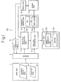
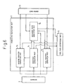
- Figure 1 is a block diagram showing a control apparatus 100 for a machine tool according to an embodiment of the present invention.
- the control apparatus 100 includes, as main components thereof, an input unit 1, a database 3, a tool path determining unit 5 and a predictive calculation unit 7. Though not shown in detail, the control apparatus 100 can be configured of a CPU, a RAM, a ROM, an input/output interface, a data memory and a bidirectional bus for connecting these component elements.
- the operator inputs the machining profile data 1a of a product to be machined from an input unit 1.
- This machining profile data 1a can be, for example, electronic pattern information such as CAD data.
- the machining profile data 1a includes data on the machining accuracy and the surface roughness.
- the input unit 1 is further supplied with workpiece data 1b providing data on the profile and the material of the workpiece to be machined for making the product.
- the workpiece data 1b include data on the dimensions and profiles of the fittings, jigs such as pallets, etc. for mounting and fixing the work on the machine tool 11, the mounting position on the machine tool 11 and the mounting position of the workpiece to be machined on a jig.
- the input unit 1 includes not only a keyboard but also such information media as a floppy disk and a magneto-optical disk, driving units thereof and an interface to a network which stores the data.
- the data input by way of the input unit 1 are stored in the database 3 functioning as a data storage means.
- the database 3 includes a machine database 3a, a tool/holder database 3b, a machining conditions database 3c, a material database 3d, a NC/servo database 3e and an input database 3f.
- the database 3 can be configured of a data storage unit such as a hard disk drive or an optical disk device.
- the machine database 3a, the tool/holder database 3b, the machining conditions database 3c, the material database 3d, the NC/servo database 3e and the input database 3f in the database 3 can be configured either as different data storage units or can be incorporated in a single data storage unit partitioned into a plurality of areas assigned the databases 3a to 3f, respectively.
- the data stored in the machine database 3a include those on the stroke of each feed shaft, the maximum rotational speed of the main spindle, and the maximum feed rate of the machine tool 11, and the deformation characteristic of the machine tool 11 with respect to temperature and the deformation characteristic of the machine tool 11 due to the weight of the work.
- the data stored in the tool/holder database 3b includes serial numbers of the tools, dimensions and the shape of the tool holder, material and life of the tools, the trip characteristic and the run-out characteristic of the tools under load, and the dimensions and shape of the forward end of the main spindle.
- the data stored in the machining conditions database 3c include the amount of feed and the amount of cut per blade, the pick feed amount, whether coolant is used or not, the machining pattern, the partitioning data for dividing the machining surface into a plurality of machining areas, and fundamental data for selecting an optimum tool for machining a given machining surface.
- the data stored in the material database 3d include the type, hardness, tensile strength, modulus of elasticity, etc. of a material.
- the data stored in the NC/servo database 3e include specifications, setup parameters, time constant of the servo, and the gain of the numerical control unit.
- the input database 3f has stored therein the machining profile data 1a and the workpiece data 1b input from the input unit 1.
- the data stored in the database 3 are at least one of the data input arbitrarily by the operator, the data registered in the machine tool 11 and the data stored in a predetermined memory.
- the tool path determining unit 5 will be described with reference to Figures 3 and 4.
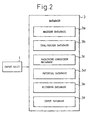
- the tool path determining unit 5 includes a machining process determining unit 5a, a tool path generating unit 5b, a machining conditions determining unit 5c and a correction unit 5d described in detail below.
- the machining profile data 1a and the workpiece data 1b stored in the input database 3f are sent to the machining process determining unit 5a (step S11). Based on these data, the machining process determining unit 5a recognizes the profile of the machining surface of the workpiece to be machined and the work to be finished. Then, the machining process determining unit 5a partitions the machining surface into a plurality of machining areas with the curvature, the inclination and depth of the surface to be machined as surface parameters based on the surface partitioning data stored in the machining conditions database 3 and the recognized profile of the machining surface (step S13).
- the machining process determining unit 5a selects an optimum tool and an optimum machining pattern for machining each machining area in accordance with each surface parameter thereof (step S15).
- the tool would be overloaded or develop a shimmy.
- a machining path along a contour is selected for a steep slope.
- the data on whether a cooling is required to be supplied or not is introduced from the machining conditions database 3c. Then, the order of machining the respective machining areas is determined (step S17).
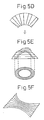
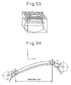
- Figures 5A to 5H Examples of machining patterns are shown in Figures 5A to 5H.
- Figure 5A shows a scan machining path
- Figure 5B a contour machining path.
- Figure 5C shows a scan machining path, i.e. what is called the character line machining path, intended to improve the cutting efficiency by setting only the portion having a work as a machining area
- Figure 5D is a radiation machining path centered at about a point O.
- Figure 5E shows a contour machining path for a work having a substantially predetermined stock allowance from a final profile of a material such as cast iron which is cutting a predetermined amount each time along the direction of the normal to the final profile by progressively offsetting the work
- Figure 5F shows a scan machining path for a work having a substantially predetermined stock allowance from a final profile of a material such as cast iron which is cut a predetermined amount each time progressively along the direction of the normal to the final profile thereof.
- Figure 5G shows a contour machining path intended to improve the cutting efficiency by defining a machining area only at the portion covered by a work, and starting the machining operation with the portion covered by a work or decreasing the pick feed rate when the work approaches a final profile, for example.
- Figure 5H shows a machining path, in which the boundary of a machining area is overlapped automatically with an adjacent machining area, and the tool is retracted over the overlapped portion smoothly thereby to prevent a misalignment at the boundary.
- the tool begins to be moved along the normal from a relief point a predetermined distance off the tool path associated with the size of the particular tool toward the machining area, within which the tool is moved along the tool path corresponding to the size of the particular tool to cut the machining area.
- machining patterns are stored in the database 3 in a form reflecting the accumulated know-how in such a manner that a desired machining pattern can be selected for a corresponding surface parameter such as the curvature, inclination and depth of each machining area.
- the shown machining patterns represent only several examples to which the present invention is not limited.
- the data determined in the machining process determining unit 5a on the machining area, the tool, the machining pattern and the machining sequence are sent to the tool path generating unit 5b.
- the tool path generating unit 5b determines optimum values of the feed rate per blade, the depth of cut and the pick feed length for machining a particular work from various amounts of these parameters stored in the machining conditions database 3c in correspondence with the data on the machining area, the tool, the machining pattern, the workpiece data 1b, in particular, the data on the material of the workpiece to be machined, stored in the input database 3f, and the data on the type, tensile strength and modulus of elasticity of the material stored in the material database 3d, while at the same time generating a tool path and a pick feed path.
- the tool path and the pick feed path are generated according to the formula stored in the machining conditions database 3c.
- the operator can arbitrarily input the data on the tool, the machining pattern and the machining process.
- the machining conditions determining unit 5c determines the rotational speed of the main spindle and the feed rate of the machine tool 11 from the feed rate, the cut rate and the pick feed rate per blade based on the result of the calculation input from the tool path generating unit 5b, while at the same time applying a tool change command for each step of the process and a command for inserting a step of measurement by a sensor unit 13 described later to a numerical control unit 9.
- the correction unit 5d issues a correction command to the tool path generating unit 5b or the machining process determining unit 5a based on the result of the predictive calculation input from the predictive calculation unit 7 described later.
- the machining conditions arbitrarily input by the operator or the machining conditions stored in a predetermined memory can be used with equal effect.
- the numerical control unit 9 generally includes a well-known NC unit 9a and a servo system 9b having a servo motor and an amplifier for controlling the revolutions of the main spindle of the machine tool 11.
- the NC unit 9a generates a command for moving each of the X, Y and Z feed shafts based on the tool path data and the machining conditions data, as is well known, while at the same time issuing commands for starting/stopping the main spindle, turning on/off the coolant, automatically changing the tool and automatically changing the pallet, etc. of the machine tool 11.
- the servo system 9b in response to a move command from the NC unit 41, controls the servo motor of the feed shaft. In this way, the machine tool 11 is controlled by the numerical control unit 9.
- the machine tool 11 is well-known equipment such as a machining center having an automatic tool changer, for example.
- the machine tool 11 comprises a sensor unit 13 including machine sensors having a temperature sensor such as thermistord for measuring the temperature of various parts of the machine such as the column and the bed, the coolant and the environment in which the machine tool 11 is installed, and an ampere meter for measuring the current value supplied to the motor of the machine tool 11, a tool sensor for measuring the length, diameter and the profile of the forward end of the tool mounted on the machine tool 11, and a work sensor for measuring the profile of the work being machined.
- the values detected by the sensor unit 13 are sent to the predictive calculation unit 7 described later. Further, the tool length, the tool diameter, the wobble of the tool in rotation, the off-center, etc. measured by the tool sensor of the sensor unit 13 are sent through the data correction unit 15 to the tool/holder database 3b of the database 3.
- the contents of the database 3, especially, the friction characteristic, the service life and the wobble characteristic of the tool are corrected and updated
- the temperature of various parts of the machine body, the coolant temperature, the temperature of the environment, etc. measured by the temperature sensor included in the mechanical sensor of the sensor unit 13 are applied through the data correction unit 15 to the machine database 3a of the database 3, so that the related portion of the machine database 3a is corrected and updated.
- the positioning error of the machine tool 11 in operation is calculated from the machining error measured by the work sensor of the sensor unit 13, and applied through the data correction unit 15 to the machine database 3a of the database 3, so that the corresponding portion of the machine database 3a is corrected and updated.
- the predictive calculation unit includes, as main component elements thereof, a machining state simulation unit 7a, a machine behavior simulation unit 7b, a workpiece simulation unit 7c and a tool behavior simulation unit 7d.
- the machining state simulation unit 7a receives the machining profile data 1a and the workpiece data 1b from the input database 3f, and the dimensions and the profile of the tool, the tool holder and the forward end of the main spindle determined by the machining process determining means 5a from the tool/holder database 3b. Further, the machining state simulation unit 7a receives the feed rate, the cut rate, the pick feed rate, the tool path and the pick feed path per blade determined and calculated by the tool path generating unit 5b and also receives the rotational speed of the main spindle and the feed rate determined by the machining conditions determining unit 5c.
- the machining state simulation unit 7a before starting the machining process, i.e. when the tool path determining unit 5 first generates a tool path or the like, predicts whether the tool, the tool holder or the forward end of the main spindle interferes with the work during the machining operation based on the machining profile data 1a, the workpiece data 1b, and the profile and dimensions of the tool, the tool holder and the forward end of the main spindle, the tool path and the pick feed path. In the case where interference is predicted during the machining operation in a given machining area, the machining state simulation unit 7a instructs the machining process determining unit 5a to define the same machining area as a no-machining area.
- the machining process determining unit 5a changes the tool or the machining pattern, as the case may be, determines the machining area, the tool, the machining pattern and the machining sequence afresh, and sends the result to the tool path determining unit 5. Then, this process is executed again. In the case where the tool or the machining pattern cannot be changed, on the other hand, the machining process determining unit 5a sends the machining sequence with the no-machining area removed from the machining process to the tool path determining unit 5.
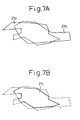
- the machining process determining unit 5a can alternatively define a range to be machined as a portion overlapped between the machining area determined by checking for interference between the tool and the work as in the method shown in Figures 7A, 7B, the machining area arbitrarily determined by checking the machining profile data 1a input from the input unit 1 for any interference between the work and the tool and the machining area determined according to the surface inclination, the surface curvature and the depth included in the machining profile data 1a input from the input unit 1.
- the machining state simulation unit 7a further checks, in real time, for a similar interference also after the machining process has started. In the case where interference between the tool and the work is predicted as a result of the check, a data indicating it is applied to the tool path generating unit 5b. The tool path generating unit 5b calculates and generates a machining route avoiding the interference such as along the Z-axis.
- the machining state simulation unit 7a predicts an internal-angle portion of the work being machined, based on the machining profile data 1, the workpiece data 1b, the machining pattern and the tool path while the actual machining work is going on. The result of prediction is applied to the machining conditions determining unit 5c, which generates machining conditions for decelerating the tool feed rate at the internal-angle portion.
- the machining state simulation unit 7a predicts by calculation a machining load from the workpiece data 1b, the feed rate, the cut rate, the pick feed rate and the tool path per bite determined and calculated by the tool path generating unit 5b, and the rotational speed of the main spindle and the feed rate determined by the machining conditions determining unit 5c.
- the machining state simulation unit 7a predicts the current profile or the work being machined, the contact point between the tool and the work and the weight of the work, from the machining profile data 1a, the workpiece data 1b, the profile and dimensions of the tool, the tool holder and the forward end of the main spindle determined by the machining process determining unit 5a, and the pick feed rate and the tool path determined and calculated by the tool path generating unit 5b.
- the machining state simulation unit 7a predicts the load inertia of the work based on the predicted work weight change and the machining conditions determined by the machining conditions determining unit 5c.
- the predicted load inertia is applied to the numerical control unit 9 for correcting the parameters of the servo system 9b of the numerical control unit 9.
- the machining state simulation unit 7a sends data informing the machining conditions determining unit 5c of the fact.
- the machining conditions determining unit 5c can give a command to the numerical control unit 9 to move the tool along the tool path at a maximum feed rate through the air-cut predicted area.
- the machine behavior simulation unit 7b predicts the thermal deformation of the machine tool 11 based on the data on the thermal deformation characteristic of the machine against the temperature stored in the machine database 3a and the temperature data supplied from the temperature sensor of the sensor unit 13. Also, the machine behavior simulation unit 7b predicts the deformation of the machine tool 11 due to the work weight based on the work weight data predicted by calculation in the machining state simulation unit 7a and the deformation characteristic data of the machine under the weight of the work stored in the machine database 3a.
- the workpiece simulation unit 7c receives the machining profile data 1a and the workpiece data 1b from the input database 3f, and receives, from the tool/holder database 3b, the dimensions and profile of the tool, the tool holder, and the forward end of the main spindle determined by the machining process determining unit 5a. Further, the workpiece simulation unit 7c receives the feed rate, the cut rate, the pick feed rate, the tool path and the pick feed path per blade determined and calculated by the tool path determining unit 5b, and also receives the rotational speed of the main spindle and the feed rate determined by the machining conditions determining unit 5c. The workpiece simulation unit 7c predicts by calculation an intermediate profile of the work being machined at each moment based on the data received from the database, and applies the result of predictive calculation to the machining state simulation unit 7a and the machine behavior simulation unit 7b.
- the tool behavior simulation unit 7d predicts the trip and the run-out of the tool from the data on the machining load predicted by the machining state simulation unit 7a and the data on the trip and the run-out characteristics with respect to the tool load stored in the tool/holder database 3b. Also, the tool behavior simulation unit 7d predicts by calculation the wear and the wear distribution of the tool from the data on the tool life stored in the tool/holder database 3b and the machining load, the machining contact point, the cut rate and the machining time predicted by the machining state simulation unit 7a.
- the wear distribution is defined as a prediction, for a ball end mill, for example, as to whether the forward end of the mill wears, and at which position the forward end wears, the straight portion or other portions.
- the expiry of the service life of the tool is judged from the predictive calculation of the wear. Further, the tool sensor of the sensor unit 13 corrects the prediction value based on the change in the tool profile (diameter, length, center position, orientation, etc. of the tool) while turning.
- the trip predictively calculated in the tool behavior simulation unit 7d is sent to the correction unit 5d of the tool path determining unit 5.
- the tool generating unit 5b generates a tool path taking the tool trip into account.
- the feed rate is required to be corrected in such a manner that the forward end of the tool on the main spindle moves to a predetermined machining position in order to permit the required machining operation. A high-precision machining operation thus becomes possible.
- the display unit 17 includes an image processing unit 17a and a monitor 17b such as a CRT.
- the display unit 17 can display the machining area, the machining pattern, the profile and the serial number of the tool, etc. determined in the machining process determining unit 5a of the tool path determining unit 5.
- the image processing unit 17a receives the data on the curvature, the inclination and the depth of the machining area from the machining process determining unit 5a and can generate the data for displaying each area three-dimensionally in different colors.
- the image processing unit 17a is connected to the database 3, the predictive calculation unit 7, the numerical control unit 9 and the sensor unit 13 and thus can display the information from each of these component parts graphically or as a text.
- the display unit 17 can graphically display, for example, the result of the check for the work-tool interference based on the data from the predictive calculation unit 7. Further, the data on the machining accuracy included in the machining profile data 1a input to the input database 3f and the work profile measurement data obtained in the sensor unit 13 can be displayed in comparison with each other. Also, as described already, it is possible to graphically display the portion of the work remaining uncut by a machining path avoiding the work-tool interference.
- the operator inputs the machining profile data 1a and the workpiece data 1b from the input unit 1 into the database 3.
- the tool path determining unit 5 selects and determines a machining area, a tool, a machining pattern and a machining process.
- a tool path is determined by the tool path generating unit 5b of the tool path determining unit 5, and machining conditions by the machining conditions determining unit 5c.
- the machine tool 11 is driven under the control of the numerical control unit 9 according to the machine drive data including the tool path and the machining conditions generated and determined. In this way, the work is machined and a product is finished.
- the predictive calculation unit 7 makes various calculations for predicting the machining load and the work-tool interference based on the machining profile data 1a and the workpiece data 1b input by the operator from the input unit 1 and the various data stored in the database 3.
- the result of predictive calculation is applied to the machining process determining unit 5a of the tool path determining unit 5.
- a tool, a machining pattern and a machining process are thus determined in the predictive calculation unit 7 according to the result of predictive calculation.
- a tool path is determined by the tool path generating unit 5b of the tool path determining unit 5 and machining conditions by the machining conditions determining unit 5c.
- the predictive calculation unit 7 for predicting the machining load, the interference between the work and the tool, etc. based on the machining profile data 1a and the workpiece data 1b input from the input unit 1 and the data stored in the database 3.
- the method according to the present invention starts with predictive calculations, and the result of the predictive calculations is fed forward and used for machining the work. Also, the detected machining requirement is fed back for further improving the accuracy of the feedforward control. Consequently, the operation is optimized and the work can be machined with high accuracy and move quickly than in the prior art.
- the operator inputs only the profile data on the product to be machined and the data on the profile and material of the work to be loaded and machined.
- the operation of machining a work meeting the precision requirement can be automatically performed within a shorter length of time as a process meeting the required accuracy is executed automatically with a proper tool, along a proper tool path and under proper machining conditions.
- FIGs 8A, 8B An example comparison between the prior art and the present invention is shown in Figures 8A, 8B.
- the feed rate of the tool is kept so high that the work is machined at 6 m/min, for example, in performing the machining operation. Corners are often undesirably dulled as shown by one-dot chain in Figure 8B (the portions designated by reference numerals 23a, 23b) and the radius of curvature is shortened (the portion designated by numeral 23c).
Landscapes
- Engineering & Computer Science (AREA)
- Physics & Mathematics (AREA)
- General Physics & Mathematics (AREA)
- Geometry (AREA)
- Human Computer Interaction (AREA)
- Manufacturing & Machinery (AREA)
- Automation & Control Theory (AREA)
- Mechanical Engineering (AREA)
- Numerical Control (AREA)
- Electrical Discharge Machining, Electrochemical Machining, And Combined Machining (AREA)
- Exchange Systems With Centralized Control (AREA)
- Turning (AREA)
- Finish Polishing, Edge Sharpening, And Grinding By Specific Grinding Devices (AREA)
- Automatic Tool Replacement In Machine Tools (AREA)
- Constituent Portions Of Griding Lathes, Driving, Sensing And Control (AREA)
Claims (44)
- Steuervorrichtung für eine Werkzeugmaschine (100) mit einer Formgeburigspiofildateneingabe, um ein Erzeugnis zu bearbeiten, umfassend:Eingabemittel (1) zum Eingeben von Formgebungsprofildaten (1a) über das Endprofil eines Erzeugnisses und Werkstückdaten (1b) über das Material und das Profil des Erzeugnisses bevor es bearbeitet wird; Datenspeichermittel (3) zum Speichern von Maschinendaten, die Maschinenspezifikationen der Werkzeugmaschine (11) zum Bearbeiten des Erzeugnisses und/oder Spezifikationen der Schneidewerkzeuge in der Werkzeugmaschine darstellen, und Werkzeugwegerfassungsmittel (5) zum Erzeugen eines Werkzeugwegs zum Bearbeiten des Erzeugnisses, basierend auf den Eingabedaten von dem Eingabemittel (1) und den in dem Datenspeichermittel (3) gespeicherten Daten und Bestimmen der Bedingungen, einschließlich der Drehzahl der Hauptspindel und der Zuführgeschwindigkeit der Werkzeugmaschine (11) zum Bearbeiten des Erzeugnisses, und gekennzeichnet durch Vorhersageberechnungsmittel (7) zum Vorhersagen durch Berechnung mindestens eines ausgewählt ist unter einer Maschinenbelastung und einer Störung zwischen einem Werkzeug und einem Erzeugnis, basierend auf der Dateneingabe von dem Eingabemittel (1) und der in dem Datenspeichermittel (3) gespeicherten Daten.
- Steuervorrichtung für eine Werkzeugmaschine (100) nach Anspruch 1, worin die in dem Datenspeichermittel (3) gespeicherten Daten mindestens einen durch den Bediener willkürlich eingegebenen ausgewählten Datensatz umfassen, die in der Werkzeugmaschine (11) eingetragenen Daten und die vorher in einem bestimmten Speichermittel gespeicherten Daten.
- Steuervorrichtung für eine Werkzeugmaschine (100) nach Anspruch 1, worin das Erfassungsmittel für einen Werkzeugweg (5) ein Werkzeug und ein Formgebungsmuster auswählt und Bestimmungsmittel für ein Formgebungsverfahren (5a) zum Bestimmen eines Formgebungsverfahrens umfasst.
- Steuervorrichtung für eine Werkzeugmaschine (100) nach Anspruch 3, worin das durch das Bestimmungsmittel für ein Formgebungsverfahren (5a) ausgewählte und bestimmte Werkzeug, Formgebungsmuster und Bearbeitungsverfahren, die durch den Operator willkürlich eingegebenen Daten darstellen.
- Steuervorrichtung für eine Werkzeugmaschine (100) nach Anspruch 1, worin das Bestimmungsmittel für einen Werkzeugweg (5) ein Werkzeug und ein Formgebungsmuster auswählt und Bestimmungsmittel für ein Formgebungsverfahren (5a) zum Bestimmen eines Formgebungsverfahrens umfasst und worin das Bestimmungsmittel für ein Fonngebungsverfahren (5a) ein Werkzeug, ein Formgebungsmuster und ein Formgebungsverfahren auswählt und bestimmt, basierend auf der Dateneingabe aus dem Eingabemittel (1), den in dem Datenspeichermittel (3) gespeicherten Daten und dem Ergebnis einer Vorhersageberechnung durch das Vorhersageberechungsmittel (7).
- Steuervorrichtung für eine Werkzeugmaschine (100) nach Anspruch 1, worin die Formgebungsbedingungen, die durch das Bestimmungsmittel für einen Werkzeugweg (5) bestimmt werden, mindestens bestehen aus einem der durch den Operator willkürlich eingegebenen ausgewählten Datensätze und den vorher in einem bestimmten Speichermittel gespeicherten Daten.
- Steuervorrichtung für eine Werkzeugmaschine (100) nach Anspruch 5, worin das Bestimmungsmittel für einen Werkzeugweg (5) die Formgebungsbedingungen basierend auf den in dem Datenspeichermittel (3) gespeicherten Daten, dem erzeugten Werkzeugweg, dem Ergebnis der vorsagbaren Berechnung durch das Vorhersageberechnungsmittel (7) bestimmt und das Werkzeug, das Formgebungsmuster und das Formgebungsverfahren durch das Bestimmungsmittel für einen Formgebungsverfahren (5a) ausgewählt und bestimmt werden.
- Steuervorrichtung für eine Werkzeugmaschine (100) nach Anspruch 1, weiter umfassend ein Erfassungsmittel für ein Formgebungsprofil zum Erfassen des Profils eines bearbeiteten Produktes, worin das Ergebnis der Erfassung dem Bestimmungsmittel für einen Werkzeugweg (5) zurückgemeldet wird, wodurch zum Verbessern der Formgebungsgenauigkeit der genaue Werkzeugweg korrigiert wird.
- Steuervorrichtung für eine Werkzeugmaschine (100) nach Anspruch 8, worin die Inhalte der in dem Datenspeichermittel (3) gespeicherten Maschinendaten basierend auf dem Ergebnis einer Erfassung durch das Erfassungsmittel für ein Formgebungsprofil aktualisiert werden, wodurch die Genauigkeit der Vorhersageberechnung in dem Vorhersageberechnungsmittel (7) verbessert wird.
- Steuervorrichtung für eine Werkzeugmaschine (100) nach Anspruch 1, weiter umfassend einen Maschinensensor (13) zum Erfassen der Temperatur oder dergleichen des Körpers der Werkzeugmaschine (11) und zurückmelden des Erfassungsergebnisses an das Vorhersageberechnungsmittel (7).
- Steuervorrichtung für eine Werkzeugmaschine (100) nach Anspruch 1 weiter umfassend einen Werkzeugsensor (13) zum Erfassen der Abmessungen und des Profils eines in der Werkzeugmaschine (11) angebrachten Schneidewerkzeugs und Zurückmelden des Erfassungsergebnisses an die Vorhersageberechnungsmittel (7).
- Steuervorrichtung für eine Werkzeugmaschine (100) nach Anspruch 1 weiter umfassend einen Maschinensensor (13) zum Erfassen des in einem Motor fließenden Stroms, der Temperatur des Körpers des Werkzeugmaschine (11), etc. und einen Werkzeugsensor (13) zum Erfassen der Abmessungen und des Profils eines in der Werkzeugmaschine (11) angebrachten Schneidewerkzeugs, worin das Erfassungsergebnis an das Vorhersageberechnungsmittel (7). zurückgemeldet wird.
- Steuervorrichtung für eine Werkzeugmaschine (100) nach Anspruch 12, worin die Inhalte, ausgewählt aus einem, der in dem Datenspeichermittel (3) gespeicherten Maschinendaten und Werkzeugdaten, basierend auf den Erfassungsdaten ausgewählt aus einem des Maschinensensors (13) und des Werkzeugsensors (13) aktualisiert werden, wodurch die Genauigkeit der Vorhersageberechnung in dem Vorhersageberechnungsmittel (7) verbessert wird.
- Steuervorrichtung für eine Werkzeugmaschine (100) nach Anspruch 1, worin das Vorhersageberechnungsmittel (7) ein Erzeugnissimulationsmittel (7c) zum Vorhersagen des Profils des bearbeiteten Erzeugnisses umfasst, basierend auf den Werkstückdateneingabe aus dem Eingabemittel (1), den in dem Datenspeichermittel (3) gespeicherten Daten und dem Werkzeugweg und den in dem Bestimmungsmittel für einen Werkzeugweg (5) erzeugten und bestimmten Formgebungsbedingungen.
- Steuervorrichtung für eine Werkzeugmaschine (100) nach Anspruch 1, worin das Vorhersageberechnungsmittel (7) ein Simulationsmittel für ein Maschinenverhalten (7b) zum Vorhersagen der Änderung bei der Werkzeugmaschinenposition aufgrund der Temperatur umfasst, der Beschleunigung des Zuführschafts, der Beladungsverschiebung, etc. basierend auf den in dem Datenspeichermittel (3) und den Erfassungsdaten des Maschinensensor (13).
- Steuervorrichtung für eine Werkzeugmaschine (100) nach Anspruch 15, worin das Simulationsmittel für ein Maschinenverhalten (7b) des Vorhersageberechnungsmittels (7), die während des Formgebungsbetriebs aktuell erfasste ausgewählt aus einem der thermischen Deformationsmenge der Werkzeugmaschine und der durch Berechnung vorhergesagten thermischen Deformationsmenge, basierend auf den Erfassungsdaten des Maschinensensors (13) an das Bestimmungsmittel für einen Werkzeugweg (5) ausgibt, wodurch das Bestimmungsmittel für einen Werkzeugweg (5) angewiesen wird einen Werkzeugweg zu erzeugen, der die Formgebungsgenauigkeit nicht schädigt, was andererseits durch die thermische Deformation der Werkzeugmaschine verursacht werden könnte.
- Steuervorrichtung für eine Werkzeugmaschine (100) nach Anspruch 1, worin das Vorhersageberechnungsmittel (7) ein Simulationsmittel für ein Werkzeugverhalten (7d) umfasst, basierend auf den in dem Datenspeichermittel (3) gespeicherten Daten und den Erfassungsdaten des Werkzeugsensors (13) zum Vorhersagen der Länge, des Durchmessers, Arbeitsspiels, Blattposition, Abnutzung, etc. des Werkzeugs bei Drehung.
- Steuervorrichtung für eine Werkzeugmaschine (100) nach Anspruch 17, worin das Bestimmungsmittel für ein Werkzeugverhalten (7d) des Vorhersageberechnungsmittels (7) das Arbeitsspiels, die Abnutzung, etc. des Werkzeugs vorhersagt und das Ergebnis der Vorhersageberechnung an das Bestimmungsmittel für einen Werkzeugweg (5) ausgibt, wodurch das Bestimmungsmittel für einen Werkzeugweg (5) angewiesen wird einen Werkzeugweg zu erzeugen, der die Formgebungsgenauigkeit nicht schädigt, was andererseits durch Arbeitsspiel oder Abnutzung des Werkzeugs verursacht werden könnte.
- Steuervorrichtung für eine Werkzeugmaschine (100) nach Anspruch 12, worin das Vorhersageberechnungsmittel (7) umfasst:Erzeugnissimulationsmittel (7c) zum Vorhersagen des Profils eines bearbeiteten Erzeugnisses, basierend auf den in das Eingabemittel (1) eingegebenen Werkstückdaten, den in dem Speichermittel (3) gespeicherten Daten und dem Werkzeugweg und den durch das Bestimmungsmittel für einen Werkzeugweg (5) erzeugten und bestimmten Formgebungsbedingungen: Simulationsmittel für ein Maschinenverhalten (7b) zum Vorhersagen der Änderung in der Werkzengmaschinenposition aufgrund der Temperatur, der Beschleunigung des Zuführschafts und der Verschiebung der Last, etc., basierend auf den in dem Speichermittel gespeicherten Daten und den Erfassungsdaten des Maschinensensors, und Simulationsmittel für ein Werkzeugverhalten (7d) zum Vorhersagen der Länge, des Durchmessers, Arbeitsspiel, Klingenposition, Abnutzung, etc. des in Drehung befindlichen Werkzeugs, basierend auf den in den in dem Speichermittel (3) gespeicherten Daten und den Erfassungsdaten des Werkzeugsensors (13), worin das Ergebnis einer Vorhersageberechnung in jedem der Simulationsmittel auf das Erfassungsmittel für einen Werkzeugweg (5) angewendet wird, und worin das Erfassungsmittel für einen Werkzeugweg (5) einen Werkzeugweg erzeugt und bestimmt und Formgebungsbedingungen mit dem Ergebnis der Vorhersageberechnung anpasst.
- Steuervorrichtung für eine Werkzeugmaschine (100) nach Anspruch 1, worin das Vorhersageberechnungsrnittel (7) durch Berechnung eine Formgebungsbelastung vorhersagt und das Ergebnis der Vorhersageberechnung auf das Erzeugungsmittel für einen Werkzeugweg (5b) anwendet, wodurch ein Werkzeugweg zur Verringerung der Werkzeugdeformation aufgrund der Formgebungsbelastung erzeugt wird, die durch das Bestimmungsmittel für einen Werkzeugweg (5) vorhergesagt wird,.
- Steuervorrichtung für eine Werkzeugmaschine (100) nach Anspruch 1, worin das Vorhersageberechnungsmittel (7) einen Luftschneidebereich vorhersagt, in dem das Werkzeug das Erzeugnis nicht schneiden kann, basierend auf den Formgebungsprofildaten und den in das Eingabemittel (1) eingegebenen Werkstückdaten, und worin das Erfassungsmittel für einen Werkzeugweg (5) die Formgebungsbedingungen zur Bewegung des Werkzeugs bei einer maximalen Zuführgeschwindigkeit in dem Luftschneidebereich bestimmt.
- Steuervorrichtung für eine Werkzeugmaschine (100) nach Anspruch 1, worin das Vorhersageberechnungsmittel (7) einen Luftschneidebereich vorhersagt, in dem das Werkzeug das Erzeugnis nicht schneiden kann, basierend auf den Formgebungsprofildaten und den in das Eingabemittel (1) eingegebene Werkstückdaten, und worin das Erzeugungsmittel für einen Werkzeugweg (5b) einen Werkzeugweg erzeugt, der die Luftschneideroute auslässt.
- Steuervorrichtung für eine Werkzeugmaschine (100) nach Anspruch 1, worin das Vorhersageberechnungsmittel (7) einen Innenwinkelabschnitt des bearbeiteten Erzeugnisses vorhersagt, basierend auf den Fornngebungsprofildaten und den in das Eingabemittel (1) eingegebenen Werkstückdaten und das Ergebnis der Vorhersage auf das Erfassungsmittel für einen Werkzeugweg (5) anwendet und die Formgebungsbedingungen zur Verlangsamung der Zuiuhrgeschwindigkeit bei dem Innenwinkelabschnitt bestimmt.
- Steuervorrichtung für eine Werkzeugmaschine (100) nach Anspruch 14, worin das Maschinenmittel (11) numerische Steuermittel (9) umfasst und die Datenspeichermittel (3) weiter darin gespeichertes Datenmaterial aufweisen einschließlich der Härte, Zugfestigkeit und Elastizitätsmodul verschiedener Materialien des Erzeugnisses, worin das Vorhersageberechnungsmittel (7) die Gewichtsänderung des Erzeugnisses vorhersagt, basierend auf den Profildaten des bearbeiteten Erzeugnisses und der in dem Datenspeichermittel gespeicherten Materialdaten und weiter eine Belasiungsträgheit vorhersagt, basierend auf der vorhergesagten Erzeugüisgewichtsänderung und der Formgebuagsbedingungen, die durch das Erfassungsmittel für einen Werkzeugweg (5) bestimmt werden, und worin die vorhergesagte Belastungsträgheit auf das numerische Steuermittel (9) angewendet wird, das wiederum die Parameter korrigiert.
- Steuervorrichtung für eine Werkzeugmaschine (100) nach Anspruch 24, worin das Vorhersageberechnungsmittel (7) das gegenwärtige Formgebungsverfahren und die erforderliche Genauigkeit erkennt, das erkannte Formgebungsverfahren und die erforderliche Genauigkeit auf das numerische Steuerminel (9) anwendet, und das numerische Steuermittel (9) anweist die Parameter zu korrigieren.
- Steuervorrichtung für eine Werkzeugmaschine (100) nach Anspruch 14, worin das Vorhersageberechnungsmittel (7), basierend auf dem Vorhersageprofil des in dem Erzeugnissimulationsmittel (7c) bearbeiteten Erzeugnisses prüft, ob eine Störung zwischen einem Werkzeug und einem Erzeugnis vorliegt.
- Steuervorrichtung für eine Werkzeugmaschine (100) nach Anspruch 1, worin nach dem Bestimmen des ausgewählten Fonngebungsbereichs, basierend auf den Werkstückdaten und den in das Eingabemittel (1) eingegebenen Erzeugnisprofildaten und ein Werkzeugs zur Formgebung des Formgebungsbereichs, wobei das Vorhersageberechnungsmittel (7) prüft, ob eine Störung zwischen dem Werkzeug und dem Erzeugnis in dem Formgebungsbereich vorliegt und worin das Bestimmungsmittel für ein Formgebungsverfahren (5a) den Formgebungsbereich als einen Bereich bestimmt, der in Abwesenheit einer Störung bearbeitet werden kann und den Formgebungsbereich als einen Bereich bestimmt, der in Gegenwart einer Störung nicht bearbeitet werden kann, wie durch die Berechnung einer Störungsvorhersage bestimmt wird.
- Steuervorrichtung für eine Werkzeugmaschine (100) nach Anspruch 1, worin Vorhersageberechnungsmittel (7) die in das Eingabemittel (1) eingegebenen Formgebungsprofildaten prüft, ob eine willkürlich bestimmte Störung zwischen einem Werkzeug und einem Erzeugnis vorliegt, bestimmt einen Bereich, der, wo keine Störung vorliegt bearbeitet werden kann und einen Bereich, in dem eine Störung vorliegt nicht bearbeitet werden kann und bestimmt den Bereich, der bearbeitet werden kann als einen zu bearbeitenden Bereich.
- Steuervorrichtung für eine Werkzeugmaschine (100) nach Anspruch 3, worin das Bestimmungsmittel für ein Formgebungsverfahren (5a) die Oberflächenneigung in den in dem Eingabemittel (1) eingegebenen Forrngebungsprofildaten erkennt und den Formgebungsbereich basierend auf dem Unterschied der Oberflächenneigung unterscheidet.
- Steuervorrichtung für eine Werkzeugmaschine (100) nach Anspruch 29, weiter umfassend ein Anzeigemittel (17) zum Anzeigen unterschiedlicher Formgebungsbereiche in unterschiedlichen Farben.
- Steuervorrichtung für eine Werkzeugmaschine (100) nach Anspruch 3, worin das Bestimmungsmittel für ein Formgebungsverfahren (5a) die Oberflächenkrümmung in den in dem Eingabemittel (1) eingegebenen Formgebungsprofildaten erkennt und den Formgebungsbereich gemäß dem Unterschied in der Krümmung unterscheidet.
- Steuervorrichtung für eine Werkzeugmaschine (100) nach Anspruch 31 weiter umfassend ein Anzeigemittel (17) zum Anzeigen unterschiedlicher Formgebungsbereiche in unterschiedlichen Farben.
- Steuervorrichtung für eine Werkzeugmaschine (100) nach Anspruch 3, worin das Bestimmungsmittel für ein Formgebungsverfahren (5a) die Tiefe der in den in dem Eingabemittel (1) eingegebenen Formgebungsprofildaten erkennt und jeden Formgebungsbereich gemäß der unterschiedlichen Tiefe unterscheidet.
- Steuervorrichtung für eine Werkzeugmaschine (100) nach Anspruch 33, weiter umfassend ein Anzeigemittel (17) zum Anzeigen unterschiedlicher Formgebungsbereiche in unterschiedlichen Farben.
- Steuervorrichtung für eine Werkzeugmaschine (100) nach Anspruch 1, worin das Vorhersageberechnungsmittel (7) einerseits den überlappenden Anteil zwischen einem Formgebungsbereich, der durch das Überprüfen, ob eine Störung zwischen dem Werkzeug und dem Erzeugnis besteht, bestimmt wird oder einem willkürlich bestimmten Formgebungsbereich, der durch Prüfen der in das Eingabemittel (1) eingegebenen Formgebungsprofildaten bestimmt, ob eine Störung zwischen dem Werkzeug und dem Erzeugnis besteht als einen zu bearbeitenden Bereich bestimmt und andererseits einen Formgebungsbereich, basierend auf der Oberflächenneigung, der Oberflächenkrümmung und der Tiefe in den in dem Eingabemittel (1) eingegebenen Formgebungsprofildaten, bestimmt.
- Steuervorrichtung für eine Werkzeugmaschine (100) nach Anspruch 5, worin das Bestimmungsmittel für ein Formgebungsverfahren (5a) das Anzeigemittel (17) anweist einen Bereich, dort wo das Erzeugnis gestört wird, anzuzeigen, der nicht bearbeitet werden kann, wie durch die Werkzeugerzeugnisstörungsüberprüfung bestimmt, die durch das Vorhersageberechnungsmittel (7) ausgeführt wird.
- Steuervorrichtung für eine Werkzeugmaschine (100) nach Anspruch 5, worin das Bestimmungsmittel für ein Formgebungsverfahren (5a) einen Formgebungsbereich in dem Bereich willkürlich einstellt, der bearbeitet werden kann, wie durch die Formgebungserzeugnisstörungsprüfung in dem Vorhersageberechnungsmittel (7) bestimmt wird und das Anzeigemittel (17) anweist den eingestellten Bereich anzuzeigen.
- Steuervorrichtung für eine Werkzeugmaschine (100) nach Anspruch 1, worin das Bestimmungsmittel für einen Werkzeugweg (5) die in dem Eingabemittel (1) eingegebenen Formgebungsprofildaten und die Werkstückdaten erkennt und einen Werkzeugweg erzeugt, der dort einen Formgebungsbereich aufweist, der lediglich in einem ausgewählten Konturformgebungsmuster besteht, wo das Erzeugnis vorkommt.
- Steuervorrichtung für eine Werkzeugmaschine (100) nach Anspruch 1, worin das Bestimmungsmitiel für ein Formgebungsverfahren (5a) die in das Eingabemittel (1) eingegebenen Formgebungsprofildaten und die Werkstückdaten erkennt und einen Werkzeugweg erzeugt, der einen Satz ausgewählter Konturformgebungsmuster umfasst, wobei ein Werkzeug entlang einer der Konturformgebungsmuster zugeführt wird und nach dem vorhergehenden Konturformgebungsmuster dann in der normalen Richtung relativ zu dem Werkstück dem nächsten Konturformgebungsmuster zugeführt wird.
- Steuervorrichtung für eine Werkzeugmaschine (100) nach Anspruch 1, worin das Bestimmungsmittel für einen Werkzeugweg (5) die in das Eingabemittel (1) eingegebenen Formgebungsprofildaten und die Werkstückdaten erkennt und einen Werkzeugweg erzeugt, der dort einen Formgebungsbereich aufweist, der lediglich in einem ausgewählten Abtastformgebungsmuster besteht, wo das Erzeugnis vorkommt.
- Steuervorrichtung für eine Werkzeugmaschine (100) nach Anspruch 1, worin das Bestimmungsmittel für einen Werkzeugweg (5) die in das Eingabemittel (1) eingegebenen Formgebungsprofildaten und die Werkstückdaten erkennt und einen Werkzeugweg erzeugt, der einen Satz ausgewählter Abtastformgebungsmuster umfasst, wobei ein Werkzeug entlang einem der Abtastformgebungsmuster zugeführt wird und nachdem vorhergehenden Abtastformgebungsmuster dann in normaler Richtung relativ zu dem Werkstück dem nächsten Abtastformgebungsmuster zugeführt wird.
- Steuervorrichtung für eine Werkzeugmaschine (100) nach Anspruch 1,worin das Bestimmungsmittel für einen Werkzeugweg (5) die in das Eingabemittel eingegebenen Formgebungsprofildaten und die Werkstückdaten erkennt und einen Werkzeugweg erzeugt, um die Werkzeugverlangsamung bei einem Innenwinkelabschnitt des Erzeugnisses in einem ausgewählten Konturformgebungsmuster zu verhindern.
- Steuervorrichtung für eine Werkzeugmaschine (100) nach Anspruch 1, worin das Bestiramungsmittel für einen Werkzeugweg (5) die in das Eingabemittel (1) eingegebenen Formgebungsprofildaren und die Werkstückdaten erkennt und einen Werkzeugweg erzeugt, um die Werkzeugverlangsamung bei einem Innenwinkelabschnitt des Erzeugnisses in einem ausgewählten Abtastformgebungsmuster zu verhindern.
- Steuervorrichtung für eine Werkzeugmaschine (100) nach Anspruch 1, worin das Bestimmungsmittel für einen Werkzeugweg (5) die in das Eingabemittel (1) eingegebenen Formgebungsprofildaren und die Werkstückdaten erkennt, beginnt das Werkzeug von einem Entlastungspunkt in einer Entfernung von einem Werkzeugweg, der mit der Größe des Werkzeugs verbunden ist, aus dem Formgebungsbereich in die Richtung entlang der normalen auf den Formgebungsbereich zu hinzubewegen, bewegt das Werkzeug entlang eines Werkzeugwegs, der mit der Werkzeuggröße in dem Formgebungsbereich verbunden ist und erzeugt dadurch einen Werkzeugweg, der den Formgebungsvorgang in dem Formgebungsbereich ausführt.
Applications Claiming Priority (4)
| Application Number | Priority Date | Filing Date | Title |
|---|---|---|---|
| JP8219497 | 1997-03-15 | ||
| JP8219497 | 1997-03-15 | ||
| JP82194/97 | 1997-03-15 | ||
| PCT/JP1998/001074 WO1998041357A1 (en) | 1997-03-15 | 1998-03-13 | Machining processor |
Publications (3)
| Publication Number | Publication Date |
|---|---|
| EP0913229A1 EP0913229A1 (de) | 1999-05-06 |
| EP0913229A4 EP0913229A4 (de) | 2001-12-12 |
| EP0913229B1 true EP0913229B1 (de) | 2005-01-19 |
Family
ID=13767629
Family Applications (1)
| Application Number | Title | Priority Date | Filing Date |
|---|---|---|---|
| EP98907226A Expired - Lifetime EP0913229B1 (de) | 1997-03-15 | 1998-03-13 | Prozessor für maschinelle bearbeitung |
Country Status (9)
| Country | Link |
|---|---|
| US (1) | US6438445B1 (de) |
| EP (1) | EP0913229B1 (de) |
| JP (1) | JP3916260B2 (de) |
| KR (1) | KR100299412B1 (de) |
| AT (1) | ATE287317T1 (de) |
| CA (1) | CA2255915A1 (de) |
| DE (1) | DE69828671T2 (de) |
| IL (1) | IL126752A0 (de) |
| WO (1) | WO1998041357A1 (de) |
Cited By (2)
| Publication number | Priority date | Publication date | Assignee | Title |
|---|---|---|---|---|
| TWI675718B (zh) * | 2019-01-03 | 2019-11-01 | 財團法人工業技術研究院 | 工具機的加工件負載特性判斷及加速度調整方法 |
| EP4697104A1 (de) * | 2024-08-12 | 2026-02-18 | Makino Milling Machine Co., Ltd. | Erzeugung einer lokalen werkzeugnutzungsfunktion |
Families Citing this family (86)
| Publication number | Priority date | Publication date | Assignee | Title |
|---|---|---|---|---|
| EP1018397A1 (de) * | 1998-08-24 | 2000-07-12 | Okuma Corporation | Verfahren und geraet zur versammlung von betriebsereigniserfassung in nc bearbeitung |
| JP3998846B2 (ja) * | 1999-02-15 | 2007-10-31 | 東芝機械株式会社 | 加工情報を用いた数値制御装置 |
| DE19930859A1 (de) * | 1999-07-05 | 2001-01-18 | Sirona Dental Systems Gmbh | Verfahren zur Erstellung von medizinischen, insbesondere zahnmedizinischen Paßkörpern |
| JP2001195111A (ja) * | 2000-01-13 | 2001-07-19 | Mori Seiki Co Ltd | 加工シミュレーションにおける素材・製品形状の表示方法 |
| US6992682B1 (en) * | 2000-02-07 | 2006-01-31 | Hewlett-Packard Development Company, L.P. | Method for color management on a display device |
| JP3435117B2 (ja) * | 2000-03-09 | 2003-08-11 | 義昭 垣野 | 加工制御システム |
| AU2001249724A1 (en) * | 2000-04-03 | 2001-10-15 | Speed-Fam-Ipec Corporation | System and method for predicting software models using material-centric process instrumentation |
| US6591158B1 (en) * | 2000-06-09 | 2003-07-08 | The Boeing Company | Methods and apparatus for defining a low-curvature tool path |
| KR100383942B1 (ko) * | 2000-11-24 | 2003-05-14 | 현대자동차주식회사 | 차량용 도어실의 최적설계시스템과 그 방법 |
| JP2002189510A (ja) * | 2000-12-22 | 2002-07-05 | Mori Seiki Co Ltd | 加工関連情報生成装置、及びこれを備えた数値制御装置 |
| US6597967B2 (en) * | 2001-02-28 | 2003-07-22 | Board Of Trustees Operating Michigan State University | System and method for planning a tool path along a contoured surface |
| JP2003058215A (ja) * | 2001-08-09 | 2003-02-28 | Mori Seiki Co Ltd | 類似加工データ検索装置及び自動プログラミング装置 |
| US20030033044A1 (en) * | 2001-08-09 | 2003-02-13 | David Bilyeu | Optimized process for producing tissue products |
| KR100501319B1 (ko) * | 2002-01-22 | 2005-07-18 | 현대중공업 주식회사 | 쵸그라이너 가공 방법 |
| JP2003263208A (ja) * | 2002-03-11 | 2003-09-19 | Yoshiaki Kakino | Ncプログラムの作成方法、nc装置及びコンピュータプログラム |
| JP2004021516A (ja) * | 2002-06-14 | 2004-01-22 | Mori Seiki Co Ltd | データ通信可能な制御装置及びこれを備えたデータ伝送システム |
| JP4284491B2 (ja) * | 2002-07-16 | 2009-06-24 | 豊和工業株式会社 | ピストン外形の加工データ生成装置 |
| US20080255684A1 (en) * | 2002-11-18 | 2008-10-16 | Universiti Putra Malaysia | Artificial intelligence device and corresponding methods for selecting machinability data |
| US6895298B2 (en) * | 2003-01-17 | 2005-05-17 | The Boeing Company | Multi-axis cutter diameter compensation for numeric control machine tools |
| JP2004284002A (ja) | 2003-01-31 | 2004-10-14 | Fujitsu Ltd | 加工制御装置 |
| US7062351B2 (en) * | 2003-09-25 | 2006-06-13 | The Boeing Company | Clamp avoidance cutter path regeneration |
| JP4272206B2 (ja) * | 2003-10-23 | 2009-06-03 | 富士通株式会社 | 加工情報作成装置、プログラム及び加工情報作成方法 |
| US7451013B2 (en) * | 2004-04-29 | 2008-11-11 | Surfware, Inc. | Engagement milling |
| US7792604B2 (en) * | 2005-03-23 | 2010-09-07 | Hurco Companies, Inc. | Method of performing additive lookahead for adaptive cutting feedrate control |
| JP4737668B2 (ja) * | 2005-05-30 | 2011-08-03 | コニカミノルタセンシング株式会社 | 3次元計測方法および3次元計測システム |
| JP5013699B2 (ja) * | 2005-10-21 | 2012-08-29 | 株式会社キーエンス | 3次元加工データ設定装置、3次元加工データ設定方法、3次元加工データ設定プログラム、コンピュータで読み取り可能な記録媒体及び記録した機器並びにレーザ加工装置 |
| JP5132900B2 (ja) * | 2006-06-28 | 2013-01-30 | 株式会社キーエンス | レーザ加工条件設定装置、レーザ加工装置、レーザ加工条件設定方法、レーザ加工条件設定プログラム |
| JP4958489B2 (ja) * | 2006-06-30 | 2012-06-20 | 株式会社キーエンス | レーザ加工装置、レーザ加工条件設定装置、レーザ加工条件設定方法、レーザ加工条件設定プログラム |
| JP2008027045A (ja) * | 2006-07-19 | 2008-02-07 | Fanuc Ltd | 干渉チェック機能を備える数値制御装置 |
| JP4795886B2 (ja) * | 2006-07-27 | 2011-10-19 | 株式会社キーエンス | レーザ加工装置、レーザ加工条件設定装置、レーザ加工条件設定方法、レーザ加工条件設定プログラム |
| US8725283B2 (en) * | 2006-08-04 | 2014-05-13 | Hurco Companies, Inc. | Generalized kinematics system |
| US8024068B2 (en) | 2006-08-04 | 2011-09-20 | Hurco Companies, Inc. | Machine tool control system |
| US7933677B2 (en) * | 2006-08-04 | 2011-04-26 | Hurco Companies, Inc. | System and method for surface finish management |
| TWI353496B (en) * | 2006-08-04 | 2011-12-01 | Hurco Co Inc | System and method and computer readable medium for |
| JP4956107B2 (ja) * | 2006-09-15 | 2012-06-20 | 株式会社キーエンス | レーザ加工データ生成装置、レーザ加工データ生成方法、コンピュータプログラム及びレーザマーキングシステム |
| US20080134857A1 (en) * | 2006-12-08 | 2008-06-12 | Roach William A | Cutting head |
| KR100898034B1 (ko) * | 2007-07-11 | 2009-05-19 | (주) 엔씨비 | 공구경로 수정 방법 |
| KR100898035B1 (ko) * | 2007-07-11 | 2009-05-19 | (주) 엔씨비 | 공구경로 수정 방법 |
| JP5142880B2 (ja) * | 2008-08-06 | 2013-02-13 | 株式会社豊田中央研究所 | 加工パラメータ最適化装置、加工パラメータ最適化方法およびプログラム |
| WO2010032284A1 (ja) * | 2008-09-16 | 2010-03-25 | 新日本工機株式会社 | 数値制御装置 |
| US8295972B2 (en) * | 2008-10-07 | 2012-10-23 | Celeritive Technologies, Inc. | High performance milling |
| DE102008052592A1 (de) * | 2008-10-21 | 2010-04-22 | Trumpf Werkzeugmaschinen Gmbh + Co. Kg | Vorrichtung und Verfahren zur Steuerung einer Bearbeitungsanlage |
| JP2010108495A (ja) * | 2008-10-30 | 2010-05-13 | Mori Seiki Co Ltd | プログラミング装置 |
| JP5351550B2 (ja) * | 2009-02-20 | 2013-11-27 | 三菱重工業株式会社 | 工作機械および加工方法 |
| KR101575910B1 (ko) * | 2009-12-18 | 2015-12-08 | 두산인프라코어 주식회사 | 오차 자동 보정 기능을 가진 수치 제어 시스템 및 이를 이용한 오차 자동 보정 방법 |
| KR101776956B1 (ko) * | 2010-12-09 | 2017-09-19 | 두산공작기계 주식회사 | 공작기계의 공구 손상 탐지장치 및 공구손상 탐지방법 |
| DE102010054855B4 (de) * | 2010-12-17 | 2015-06-11 | Deckel Maho Pfronten Gmbh | Werkzeugmaschine, insbesondere programmgesteuerte Fräs- und Bohrmaschine |
| US10222781B2 (en) | 2010-12-17 | 2019-03-05 | Deckel Maho Pfronten Gmbh | Apparatus for monitoring and providing visual representations of the operating conditions of machine tool parameters |
| EP2479630A1 (de) * | 2011-01-25 | 2012-07-25 | Siemens Aktiengesellschaft | Verfahren zur kollisionsfreien Überführung einer Anlage aus einem Scheinausmodus in einen Betriebsmodus |
| US9690282B2 (en) * | 2011-02-28 | 2017-06-27 | Solidcam Ltd. | Computerized tool path generation |
| JP5792649B2 (ja) * | 2011-03-17 | 2015-10-14 | 株式会社日立製作所 | Ncプログラム生成方法 |
| US9946245B2 (en) | 2011-07-25 | 2018-04-17 | Celeritive Technologies, Inc. | Non-concentric milling |
| US8781982B1 (en) | 2011-09-23 | 2014-07-15 | Lockheed Martin Corporation | System and method for estimating remaining useful life |
| KR101302991B1 (ko) * | 2011-12-23 | 2013-09-03 | 삼성중공업 주식회사 | 절단 장비 및 그 제어 방법 |
| US10022833B2 (en) | 2012-05-03 | 2018-07-17 | Celeritive Technologies, Inc. | High performance multi-axis milling |
| JP5997577B2 (ja) | 2012-10-18 | 2016-09-28 | オークマ株式会社 | びびり振動抑制方法および工作機械 |
| US9292626B2 (en) * | 2012-12-10 | 2016-03-22 | Palo Alto Research Center Incorporated | Computer numerical control (CNC) machining tool and method for controlling a CNC machining tool |
| US9817387B2 (en) * | 2013-07-08 | 2017-11-14 | Kennametal Inc | System and method for selecting a tool assembly |
| KR101539266B1 (ko) * | 2014-07-02 | 2015-07-24 | 원시스템주식회사 | 지능형 복합 절삭가공시스템 |
| JP2016064497A (ja) * | 2014-09-16 | 2016-04-28 | 株式会社東芝 | データ補正装置、データ補正方法、及び、加工装置 |
| JP6847035B2 (ja) * | 2014-11-07 | 2021-03-24 | ヌオーヴォ ピニォーネ ソチエタ レスポンサビリタ リミタータNuovo Pignone S.R.L. | 機械加工プログラムを生成するための方法及びマシンツール |
| DE102015108531A1 (de) * | 2015-05-29 | 2016-12-01 | Kaltenbach Gmbh + Co. Kg | Werkzeugmaschine und Verfahren zur Steuerung einer Werkzeugmaschine |
| JP2017068586A (ja) * | 2015-09-30 | 2017-04-06 | ファナック株式会社 | 工具のカッタチップと被削材の衝突位置を制御する数値制御装置 |
| WO2018011990A1 (ja) * | 2016-07-15 | 2018-01-18 | 株式会社牧野フライス製作所 | 加工プログラム生成装置及び加工方法 |
| KR101878975B1 (ko) * | 2016-10-17 | 2018-07-16 | 최영일 | 저장된 가공 좌표 패턴을 이용한 부스 바 체결 홀 가공방법 및 그 가공장치 |
| GB2557952B (en) | 2016-12-16 | 2022-06-15 | Zeeko Innovations Ltd | Methods and apparatus for shaping workpieces |
| CN110100213B (zh) * | 2016-12-26 | 2022-06-24 | 三菱电机株式会社 | 加工工序生成装置及加工工序生成方法 |
| JP6470251B2 (ja) * | 2016-12-26 | 2019-02-13 | ファナック株式会社 | 数値制御装置及び機械学習装置 |
| JP6557285B2 (ja) * | 2017-05-26 | 2019-08-07 | ファナック株式会社 | 制御装置及び機械学習装置 |
| JP6781242B2 (ja) * | 2018-02-19 | 2020-11-04 | ファナック株式会社 | 制御装置、機械学習装置及びシステム |
| JP7126360B2 (ja) * | 2018-03-01 | 2022-08-26 | 株式会社牧野フライス製作所 | 工具経路を生成するための方法及び装置 |
| US11340138B1 (en) * | 2018-06-08 | 2022-05-24 | Paul Mulville | Tooling audit platform |
| IT201900004617A1 (it) * | 2019-03-27 | 2020-09-27 | Milano Politecnico | Apparato di monitoraggio per identificazione di anomalie e percorsi di degrado in una macchina utensile |
| JP7346949B2 (ja) * | 2019-07-08 | 2023-09-20 | ヤマハ株式会社 | 鍵盤、鍵盤用部品 |
| JP6999623B2 (ja) * | 2019-10-18 | 2022-01-18 | 株式会社牧野フライス製作所 | 工作機械および生産システム |
| JP7473321B2 (ja) * | 2019-10-31 | 2024-04-23 | ファナック株式会社 | シミュレーション装置、数値制御装置、及びシミュレーション方法 |
| JP7486115B2 (ja) * | 2020-03-12 | 2024-05-17 | 三菱重工業株式会社 | 低靱性加工物切削装置、低靱性加工物製造方法および低靱性加工物製造プログラム |
| CN114137908B (zh) * | 2020-09-03 | 2025-04-25 | 上海电气电站设备有限公司 | 一种车削数控编程方法、装置及数控加工系统 |
| KR102503868B1 (ko) * | 2020-11-25 | 2023-02-27 | 연세대학교 산학협력단 | 공작기계의 요소단위 에너지 소모량 예측을 위한 수치제어장치 및 방법 |
| DE102021106116A1 (de) * | 2021-03-12 | 2022-09-15 | Fraunhofer-Gesellschaft zur Förderung der angewandten Forschung eingetragener Verein | Verfahren zur Erzeugung einer virtuellen Geometrie und System zur Datenverarbeitung |
| JP7741367B2 (ja) * | 2021-07-14 | 2025-09-18 | スター精密株式会社 | 工作機械システム |
| KR102641382B1 (ko) * | 2021-09-10 | 2024-02-27 | 한국생산기술연구원 | 기상 측정을 활용한 형상 오차 보정 장치 및 그 방법 |
| WO2024122056A1 (ja) * | 2022-12-09 | 2024-06-13 | ファナック株式会社 | 処理装置及びプログラム |
| WO2024166291A1 (ja) * | 2023-02-09 | 2024-08-15 | 株式会社ニコン | 情報処理方法、情報処理装置、加工装置及び加工方法 |
| CN116165968A (zh) * | 2023-04-24 | 2023-05-26 | 成都航利航空科技有限责任公司 | 一种数控工序加工参数记录方法 |
| CN121165624B (zh) * | 2025-11-21 | 2026-02-24 | 霖鼎光学(上海)有限公司 | 一种车削刀具路径后处理方法、电子设备及存储介质 |
Family Cites Families (23)
| Publication number | Priority date | Publication date | Assignee | Title |
|---|---|---|---|---|
| KR880001305B1 (ko) * | 1982-10-12 | 1988-07-22 | 미쓰비시뎅기 가부시기가이샤 | 수치 제어 가공 방법 |
| JPS62140741A (ja) | 1985-12-13 | 1987-06-24 | Hitachi Seiki Co Ltd | 自動加工機における加工領域分割処理装置 |
| JP2514795B2 (ja) | 1986-04-12 | 1996-07-10 | 日立精機株式会社 | 工作機械における追加工処理装置 |
| JPH0766290B2 (ja) * | 1986-06-26 | 1995-07-19 | 東芝機械株式会社 | 工具経路生成方法 |
| JPH01205954A (ja) | 1988-02-08 | 1989-08-18 | Toyoda Mach Works Ltd | 工作機械の工具径路自動決定装置 |
| JPH0760336B2 (ja) | 1988-12-28 | 1995-06-28 | オ−クマ株式会社 | 数値制御装置 |
| JP2753365B2 (ja) | 1990-02-28 | 1998-05-20 | オ−クマ株式会社 | 数値制御情報作成方法 |
| JP2836633B2 (ja) | 1990-04-13 | 1998-12-14 | オ−クマ株式会社 | 数値制御情報作成機能における加工工程決定装置 |
| JP3119308B2 (ja) | 1991-03-12 | 2000-12-18 | ヤマザキマザック株式会社 | マシニングセンタ |
| JPH04284507A (ja) | 1991-03-14 | 1992-10-09 | Okuma Mach Works Ltd | 数値制御情報作成装置における加工工程データ表示方法 |
| JP2566345B2 (ja) * | 1991-05-27 | 1996-12-25 | 洋太郎 畑村 | 加工機械 |
| JPH058604U (ja) * | 1991-07-16 | 1993-02-05 | 三菱重工業株式会社 | 干渉チエツク装置 |
| JPH0577138A (ja) | 1991-09-20 | 1993-03-30 | Toyoda Mach Works Ltd | Nc面加工機のツールパス決定装置 |
| JPH05282021A (ja) * | 1992-03-31 | 1993-10-29 | Fanuc Ltd | Nc工作機械の加工条件生成方式 |
| JPH06102923A (ja) | 1992-09-18 | 1994-04-15 | Honda Motor Co Ltd | Nc加工におけるカッター送り速度制御方法 |
| JPH06114679A (ja) * | 1992-10-06 | 1994-04-26 | Fanuc Ltd | 数値制御装置の加工プログラムチェック方法 |
| JPH06119029A (ja) | 1992-10-07 | 1994-04-28 | Honda Motor Co Ltd | Nc加工におけるアプローチ経路およびリトラクト経路作成方法 |
| US5796618A (en) * | 1992-10-09 | 1998-08-18 | Omron Corporation | CAD system, method and medium for creating and encoding NC data based before and after workpiece models |
| JPH06138929A (ja) | 1992-10-29 | 1994-05-20 | Okuma Mach Works Ltd | 数値制御情報作成装置 |
| JPH08132332A (ja) | 1994-11-04 | 1996-05-28 | Fanuc Ltd | 工作機械における位置ずれ補正方法 |
| JP3702496B2 (ja) * | 1995-07-10 | 2005-10-05 | 三菱電機株式会社 | 数値制御装置を用いた加工方法 |
| JP3294146B2 (ja) | 1997-03-21 | 2002-06-24 | 早川ゴム株式会社 | 金属被覆微粒子及び導電性材料 |
| JP3251907B2 (ja) | 1998-10-19 | 2002-01-28 | オーウエル株式会社 | 減圧塗装装置 |
-
1998
- 1998-03-13 AT AT98907226T patent/ATE287317T1/de not_active IP Right Cessation
- 1998-03-13 IL IL12675298A patent/IL126752A0/xx unknown
- 1998-03-13 CA CA002255915A patent/CA2255915A1/en not_active Abandoned
- 1998-03-13 US US09/155,883 patent/US6438445B1/en not_active Expired - Lifetime
- 1998-03-13 DE DE69828671T patent/DE69828671T2/de not_active Expired - Lifetime
- 1998-03-13 JP JP54034998A patent/JP3916260B2/ja not_active Expired - Fee Related
- 1998-03-13 EP EP98907226A patent/EP0913229B1/de not_active Expired - Lifetime
- 1998-03-13 KR KR1019980709079A patent/KR100299412B1/ko not_active Expired - Fee Related
- 1998-03-13 WO PCT/JP1998/001074 patent/WO1998041357A1/ja not_active Ceased
Cited By (3)
| Publication number | Priority date | Publication date | Assignee | Title |
|---|---|---|---|---|
| TWI675718B (zh) * | 2019-01-03 | 2019-11-01 | 財團法人工業技術研究院 | 工具機的加工件負載特性判斷及加速度調整方法 |
| US10698383B1 (en) | 2019-01-03 | 2020-06-30 | Industrial Technology Research Institute | Method of load characteristic identification and acceleration adjustment for machine tool |
| EP4697104A1 (de) * | 2024-08-12 | 2026-02-18 | Makino Milling Machine Co., Ltd. | Erzeugung einer lokalen werkzeugnutzungsfunktion |
Also Published As
| Publication number | Publication date |
|---|---|
| DE69828671D1 (de) | 2005-02-24 |
| WO1998041357A1 (en) | 1998-09-24 |
| CA2255915A1 (en) | 1998-09-24 |
| ATE287317T1 (de) | 2005-02-15 |
| EP0913229A4 (de) | 2001-12-12 |
| KR20000010931A (ko) | 2000-02-25 |
| US6438445B1 (en) | 2002-08-20 |
| DE69828671T2 (de) | 2006-05-11 |
| EP0913229A1 (de) | 1999-05-06 |
| IL126752A0 (en) | 1999-08-17 |
| JP3916260B2 (ja) | 2007-05-16 |
| KR100299412B1 (ko) | 2001-10-29 |
Similar Documents
| Publication | Publication Date | Title |
|---|---|---|
| EP0913229B1 (de) | Prozessor für maschinelle bearbeitung | |
| JPWO1998041357A1 (ja) | 加工処理装置 | |
| US6535788B1 (en) | Machining apparatus | |
| US6501997B1 (en) | Numerical controlling device and tooling apparatus having thereof | |
| EP0879675A1 (de) | Verfahren und vorrichtung zur nc-bearbeitungssimulation | |
| US6662073B1 (en) | Apparatus and method for machining simulation for NC machining | |
| CN1053505C (zh) | 用于校正数控机床上刀具切削刃位置的方法和装置 | |
| US5808263A (en) | Method and apparatus for electroerosive machining | |
| US6428252B1 (en) | Method for machining | |
| JP2006068901A (ja) | 工作機械の制御装置 | |
| EP1298507A2 (de) | Verfahren zum Bestimmen des Vorschubs eines Werkzeugs und Werkzeugmaschine dafür | |
| US20200290207A1 (en) | Real-time identification of burr size and location for robotic deburring process | |
| CN116088426B (zh) | 一种带视觉装置的加工中心运动定位保护系统 | |
| Vavruska et al. | Automated feed rate optimization with consideration of angular velocity according to workpiece shape | |
| KR100600648B1 (ko) | 자동공작장치용 최적가공 컨트롤러와 상기 컨트롤러가설치된 자동공작장치 | |
| KR100439055B1 (ko) | 수치제어장치 및 캠시스템 | |
| CN110647109A (zh) | 数值控制装置 | |
| Uddin et al. | Constant engagement tool path generation to enhance machining accuracy in end milling | |
| JP3118748B2 (ja) | Nc工作機械の送り速度制御方法および装置 | |
| JP4982170B2 (ja) | 加工制御装置および加工制御プログラム | |
| US20240033873A1 (en) | Device and method for machining a workpiece | |
| US20020025758A1 (en) | Tool path preparing method and machining method | |
| JP2020160830A (ja) | 数値制御装置、工作機械、制御プログラム、及び記憶媒体 | |
| JP7829684B2 (ja) | 工作機械の操作方法 | |
| WO2024236764A1 (ja) | 異常負荷検出装置、異常負荷検出方法および異常負荷検出プログラム |
Legal Events
| Date | Code | Title | Description |
|---|---|---|---|
| PUAI | Public reference made under article 153(3) epc to a published international application that has entered the european phase |
Free format text: ORIGINAL CODE: 0009012 |
|
| 17P | Request for examination filed |
Effective date: 19981104 |
|
| AK | Designated contracting states |
Kind code of ref document: A1 Designated state(s): AT CH DE FR GB IT LI SE |
|
| A4 | Supplementary search report drawn up and despatched |
Effective date: 20011030 |
|
| AK | Designated contracting states |
Kind code of ref document: A4 Designated state(s): AT CH DE FR GB IT LI SE |
|
| 17Q | First examination report despatched |
Effective date: 20031223 |
|
| GRAP | Despatch of communication of intention to grant a patent |
Free format text: ORIGINAL CODE: EPIDOSNIGR1 |
|
| RIN1 | Information on inventor provided before grant (corrected) |
Inventor name: HISAKI, TATSUYAMAKINO MILLING MACHINE CO., LTD. Inventor name: INOUE, SHINICHIMAKINO MILLING MACHINE CO., LTD. Inventor name: KAWANA, AKIRAMAKINO MILLING MACHINE CO., LTD. Inventor name: YOSHIDA, JUN-MAKINOMILLING MACHINE CO., LTD. |
|
| GRAS | Grant fee paid |
Free format text: ORIGINAL CODE: EPIDOSNIGR3 |
|
| GRAA | (expected) grant |
Free format text: ORIGINAL CODE: 0009210 |
|
| AK | Designated contracting states |
Kind code of ref document: B1 Designated state(s): AT CH DE FR GB IT LI SE |
|
| PG25 | Lapsed in a contracting state [announced via postgrant information from national office to epo] |
Ref country code: LI Free format text: LAPSE BECAUSE OF FAILURE TO SUBMIT A TRANSLATION OF THE DESCRIPTION OR TO PAY THE FEE WITHIN THE PRESCRIBED TIME-LIMIT Effective date: 20050119 Ref country code: CH Free format text: LAPSE BECAUSE OF FAILURE TO SUBMIT A TRANSLATION OF THE DESCRIPTION OR TO PAY THE FEE WITHIN THE PRESCRIBED TIME-LIMIT Effective date: 20050119 Ref country code: AT Free format text: LAPSE BECAUSE OF FAILURE TO SUBMIT A TRANSLATION OF THE DESCRIPTION OR TO PAY THE FEE WITHIN THE PRESCRIBED TIME-LIMIT Effective date: 20050119 |
|
| REG | Reference to a national code |
Ref country code: GB Ref legal event code: FG4D |
|
| REG | Reference to a national code |
Ref country code: CH Ref legal event code: EP |
|
| REF | Corresponds to: |
Ref document number: 69828671 Country of ref document: DE Date of ref document: 20050224 Kind code of ref document: P |
|
| PG25 | Lapsed in a contracting state [announced via postgrant information from national office to epo] |
Ref country code: SE Free format text: LAPSE BECAUSE OF FAILURE TO SUBMIT A TRANSLATION OF THE DESCRIPTION OR TO PAY THE FEE WITHIN THE PRESCRIBED TIME-LIMIT Effective date: 20050419 |
|
| REG | Reference to a national code |
Ref country code: CH Ref legal event code: PL |
|
| ET | Fr: translation filed | ||
| PLBE | No opposition filed within time limit |
Free format text: ORIGINAL CODE: 0009261 |
|
| STAA | Information on the status of an ep patent application or granted ep patent |
Free format text: STATUS: NO OPPOSITION FILED WITHIN TIME LIMIT |
|
| 26N | No opposition filed |
Effective date: 20051020 |
|
| REG | Reference to a national code |
Ref country code: FR Ref legal event code: PLFP Year of fee payment: 19 |
|
| REG | Reference to a national code |
Ref country code: FR Ref legal event code: PLFP Year of fee payment: 20 |
|
| PGFP | Annual fee paid to national office [announced via postgrant information from national office to epo] |
Ref country code: FR Payment date: 20170130 Year of fee payment: 20 |
|
| PGFP | Annual fee paid to national office [announced via postgrant information from national office to epo] |
Ref country code: GB Payment date: 20170131 Year of fee payment: 20 |
|
| PGFP | Annual fee paid to national office [announced via postgrant information from national office to epo] |
Ref country code: IT Payment date: 20170310 Year of fee payment: 20 |
|
| PGFP | Annual fee paid to national office [announced via postgrant information from national office to epo] |
Ref country code: DE Payment date: 20170330 Year of fee payment: 20 |
|
| REG | Reference to a national code |
Ref country code: DE Ref legal event code: R071 Ref document number: 69828671 Country of ref document: DE |
|
| REG | Reference to a national code |
Ref country code: GB Ref legal event code: PE20 Expiry date: 20180312 |
|
| PG25 | Lapsed in a contracting state [announced via postgrant information from national office to epo] |
Ref country code: GB Free format text: LAPSE BECAUSE OF EXPIRATION OF PROTECTION Effective date: 20180312 |