EP0913666A2 - Interferenzmessapparat und - Probe - Google Patents
Interferenzmessapparat und - Probe Download PDFInfo
- Publication number
- EP0913666A2 EP0913666A2 EP98203527A EP98203527A EP0913666A2 EP 0913666 A2 EP0913666 A2 EP 0913666A2 EP 98203527 A EP98203527 A EP 98203527A EP 98203527 A EP98203527 A EP 98203527A EP 0913666 A2 EP0913666 A2 EP 0913666A2
- Authority
- EP
- European Patent Office
- Prior art keywords
- section
- optical waveguide
- substrate
- phase modulation
- luminous flux
- Prior art date
- Legal status (The legal status is an assumption and is not a legal conclusion. Google has not performed a legal analysis and makes no representation as to the accuracy of the status listed.)
- Withdrawn
Links
Images


Classifications
-
- G—PHYSICS
- G01—MEASURING; TESTING
- G01B—MEASURING LENGTH, THICKNESS OR SIMILAR LINEAR DIMENSIONS; MEASURING ANGLES; MEASURING AREAS; MEASURING IRREGULARITIES OF SURFACES OR CONTOURS
- G01B9/00—Measuring instruments characterised by the use of optical techniques
- G01B9/02—Interferometers
- G01B9/02001—Interferometers characterised by controlling or generating intrinsic radiation properties
- G01B9/0201—Interferometers characterised by controlling or generating intrinsic radiation properties using temporal phase variation
-
- G—PHYSICS
- G01—MEASURING; TESTING
- G01B—MEASURING LENGTH, THICKNESS OR SIMILAR LINEAR DIMENSIONS; MEASURING ANGLES; MEASURING AREAS; MEASURING IRREGULARITIES OF SURFACES OR CONTOURS
- G01B2290/00—Aspects of interferometers not specifically covered by any group under G01B9/02
- G01B2290/70—Using polarization in the interferometer
Definitions
- the present invention relates to an interference measurement apparatus and a probe used for an interference measurement apparatus, more particularly, to an interference measurement apparatus and a probe used for an interference measurement apparatus which utilize a phase modulation method.
- Fig. 11 shows a constitutional view of a conventional interference measurement apparatus (see the Publication of Unexamined Japanese Patent Application No. 64-88202).
- This interference measurement apparatus comprises a light source instrument 111, a half mirror 113, a movement corner cube 114, a reference corner cube 115, a polarization beam splitter 116, a detectors 117 and 118, and a signal processing circuit.
- a luminous flux P emitted from the light source instrument 111 is divided into the measurement luminous fluxes P1 and P2 by the half mirror 113 as a beam splitter.
- the measurement luminous flux P1 is reflected by the movement corner cube 114 serving as a reflection means disposed at a measurement position on the measurement optical path.
- the reference light P2 is reflected by the reference corner cube 115 disposed on the reference optical path.
- the interference light P3 of both luminous fluxes is guided to the polarization beam splitter 116 and is separated into the P and S components by the polarization beam splitter 116.
- the interference light of the P component is guided to the detector 117, and the interference light of the S component is guided to the detector 118.
- the interference signals Q1 and Q2 shifted by 90° from each other are inputted to the signal processing circuit from the detectors 117 and 118, and subjected to a predetermined signal processing by the signal processing circuit , so that the distance to the movement corner cube 114 is measured.
- Fig. 12 shows a conventional bulk type phase modulation interference measurement apparatus (see the Publication of Unexamined Japanese Patent Application No. 64-12205).
- the coherent light P emitted from a laser light source 121 is split into a reference light P1 and a measurement light P2, and the reference light P1 is reflected by a reference prism 123.
- the measurement light P2 is reflected by a measurement prism 126, and the returned reference light P1 and the returned measurement light P2 are allowed to interfere with each other and the interfered light is guided to a photodetector 125.
- a measurement prism 124 is moved to the arrow direction or to opposite direction to the arrow, and the reference prism 123 is vibrated with a predetermined period as shown by the arrow.
- the difference of the optical distance of the reference light P1 from that of the measurement light P2 is relatively changed with the predetermined period, and the interference signal based on the interference light which changes in response to the change of that difference is obtained by the photodetector 125.
- the direction of the phase change of the measurement light (movement direction of the measurement prism 124) can be obtained, the movement amount of the measurement prism 124 can be obtained without an influence of the DC bias component based on the light amount or the like.
- the structure of the optical system is complicated.
- a driving section for mechanically driving the reference prism is necessary, so, the structure of the control system is complicated.
- the prism is used as the reflection mirror, the range of use is limited by the size of the prism itself and an axial shift may occur, and it is hard to handle it.
- the object of the present invention is, by adopting a phase modulating method, to make an optical system simplified and to perform signal processing for a direction discrimination function and a high resolving detection function by one light receiving section.
- the present invention achieves a phase modulation system having no mechanical driving section by adopting phase modulation method in a waveguide device type. Moreover, the object of the present invention is to simplify a waveguide pattern so as to fit to mass production, by forming two signals having different phase only with one waveguide.
- Another object of the present invention is, by adopting a push-pull type phase modulation method, to reduce a applied voltage to approximately half and to make a voltage amplitude at the time of modulation small, thereby achieving a low power consumption type apparatus. Moreover, the object of the present invention is to provide an apparatus In which a detection precision of the displacement is not influenced by a manufacturing error of a wave plate.
- the object of the present invention is to make it easy to handle an apparatus by adopting a plane mirror as a reflection mirror and to lessen an axis shift. Moreover, the object of the present invention is to provide an interference measurement apparatus which can be easily applied to a bi-axial displacement positioning sensing system by a L-character mirror.
- an interference measurement apparatus comprising:
- a probe used for an interference measurement apparatus comprising an optical waveguide module, the optical waveguide module including:
- Fig. 1 a constitutional view of a first embodiment of an interference measurement apparatus of the present invention is shown.
- the interference measurement apparatus con,prises , a light source section 1, a connection section 2, an optical waveguide section (optical waveguide module) 3, an irradiation section 4, a polarization beam splitter section 5, a light receiving section 6, a displacement measurement section 7, a reference reflection section 8 and a measurement reflection section 9.
- this interference measurement apparatus further comprises first and second 1/4 wave plates 10 and 11 and a polarization member 12.
- the light source section 1 is composed of, for example, a laser diode or the like, which supplies a coherent light.
- the light source section I can be provided so as to separate from the optical waveguide section (optical waveguide module) 3.
- the optical waveguide 3 is disposed in a small space and the light source section 1 is disposed in another wide place, whereby measurement at a small space is possible.
- the connection section 2 is composed of means for allowing a laser light from the light source section 1 to be directly input to the optical waveguide section 3, for example, by a fiber for maintaining a polarization surface such as a polarization surface retention type single mode fiber and by a collective lens and a polarizer.
- the fiber for maintaining a polarization surface there are a single polarization fiber keeping a linear polarization surface, a coil type fiber polarizer using a coil fiber, and a bulk type fiber polarizer combined with a rod lens and a polarizer.
- Means for inputting the laser light from the light source section 1 to the optical fiber via a rod lens etc. may be provided.
- the connection section 2 supplies the laser light emitted from the light source section 1 to the optical waveguide section 3, and the laser light is incident into the optical waveguide section 3 so that the polarization direction of the linearly polarized light is approximately 45° relative to the surface of the substrate.
- a laser emitting a random polarized light is used as the light source section 1, it can also be constituted by converting the random polarized light to a linearly polarized light with a polarizer etc..
- the optical waveguide section 3 is constituted of a substrate exhibiting an electro-optic effect such as a lithium niobate crystal substrate or a lithium tantalate crystal substrate.
- a substrate exhibiting an electro-optic effect such as a lithium niobate crystal substrate or a lithium tantalate crystal substrate.
- one straight optical waveguide of X-cut type or Z-propagation type is formed, and a pair of electrodes for modulating in the Y-direction is disposed close to this optical waveguide as the phase modulation section.
- a phase modulation signal such as a sine wave signal of a predetermined frequency is applied to the electrodes, and a phase changes of approximately opposite sign is given to the TM and TE modes of the incidence luminous flux.
- the irradiation section 4 is composed of a collimator lens or the like.
- the luminous flux emitted from the optical waveguide section 3 is converted to a parallel luminous flux having an appropriate beam diameter by the irradiation section 4.
- the polarization beam splitter 5 is composed of a polarization beam splitter or the like, which allows the P and S waves to pass therethrough or reflect therefrom.
- the light receiving section 6 is constituted by appropriately using a collective lens, a ferrule, an optical fiber and the photodetector etc..
- the light receiving section 6 may be constructed in a constitution in which, in accordance with the amount of the received light, the collective lens is omitted or the optical fiber is omitted.
- the displacement measurement section 7 is constituted by a signal processing processor or the like, which obtains the displacement of the objective to be measured based on the signal received by the light receiving section 6.
- the reference reflection section 8 and the measurement reflection section 9 are constituted by, for example, a plane mirror.
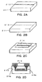
- a metal 212 for example, Ti
- the single crystal substrate 211 for example, LiNbO 3
- the single crystal substrate 211 is heated by an electric furnace or the like, whereby the metal 212 is thermally diffused into the substrate 211.
- the buried type waveguide 213 having a pattern shape is formed.
- the optical control electrode 214 is formed at a desired position.
- a metal material exhibiting a good electrical conductivity is employed as the material of the optical control electrode 214, and generally, for example, gold (Au) exhibiting stability with time is used by deposition.
- the waveguide 215 and the modulation section 216 which performs a phase modulation in the waveguide 215 can be formed.
- a coherent light from the light source section 1 is incident into the waveguide 215 from the incidence terminal 215a thereof. After the coherent light is modulated, and emitted from the emission terminal 215b of the waveguide 215.
- Fig. 3 an explanatory view of an operation of a probe used for the interference measurement apparatus is shown.
- the modulation electrodes provided in the straight waveguide have a length of l and an interval of d.
- the phase modulation signal V M is applied to the electrodes.
- the luminous flux emitted travels through the collimator lens of the irradiation section 4 and has components of the TM and TE modes, each having a polarization surface which intersects with another.
- the x, y and z-directions are as described in Fig. 3.
- Figs. 4A to 4C a view of an operational principle of superposition and interference of the TM and TE modes.
- Figs. 4A 4B and 4C a behavior of a polarized light in the sections taken on lines IV-IV, IV'- IV' and IV''-IV'' of Fig. 1, respectively.
- the TM and TE modes emitted from the optical waveguide 3 are shown as illustrated in Fig. 4A. Since the TE mode emitted from the optical waveguide 3 is the component of a P waveform for the polarization beam splitter section 5, it passes through the splitter 5 and is guided to the measurement optical path. Since the TM mode emitted from the optical waveguide is the component of a S wave for the polarization beam splitter 5, it is reflected by the splitter 5 and is guided to the reference optical path.
- the first and second 1/4 wave plates 10 and 11 are inserted between the beam splitter section 5 and the reflection plane mirror, and each polarization light passes through these 1/4 wave plates twice forward and backward, so that the first and second 1/4 wave plates 10 and 11 act on each polarization light as a 1/2 wave plate. Consequently, the reference light (TM mode) is reflected by the reference reflection section 8, and the reference light becomes the P component (TE mode) from the S component and returns to the polarization beam splitter section 5, thereby passing through the polarization beam splitter section 5.
- the measurement light (TE mode) is reflected by the measurement reflection section 9, and becomes the S component (TM mode) from the P component and then returns to the polarization beam splitter 5 again, so that it is reflected by the polarization beam splitter section 5.
- the two polarized lights are guided to the light receiving section 6 without returning to the incidence direction.
- the polarization surfaces of the polarized lights however do not interfere each other.
- the polarization direction of the polarization member 12 is set to the direction in which both components of the TM and TE modes are included, for example, the intermediate direction between the TM and TE modes.
- both polarization lights interfere for the first time after passing through the polarization member 12.
- Fig. 5 a constitutional view of a modification of the first embodiment of the interference measurement apparatus according to the present invention is shown.
- Fig. 6 an explanatory view for the interference of a push-pull type phase modulation method is shown. The operation principle will be described with reference to this drawing.
- the modulation operation of the optical waveguide section 3 is performed by utilizing a Pockels effect of the LiNbO 3 single crystal substrate.
- a change of a refractive index in the case where a voltage is applied to the Y-direction is expressed by the following expression.
- n x ⁇ n o + ⁇ n x n o -(1/2) ⁇ n o 3 ⁇ r 22 ( V d )
- n y ⁇ n o + ⁇ n y n o +(1/2) ⁇ n o 3 ⁇ r 22 ( V d )
- r 22 is a Pockels effect of the LiNbO 3 single crystal substrate
- d is the interval between the electrodes of the waveguide
- ⁇ is the modulation angular frequency
- V the applied voltage
- l is the electrode length of the waveguide.
- l is the electrode length of waveguide.
- phase changes f the polarized lights in the X and Y-directions are expressed by the following expression.
- ⁇ x - 1 2 2 ⁇ ⁇ l ⁇ n o 3 r 22 ( 1 d ) ⁇ V 0 sin( ⁇ t) ⁇ - ⁇ sin( ⁇ t)
- ⁇ y + 1 2 2 ⁇ ⁇ l ⁇ n o 3 r 22 ( 1 d ) ⁇ V 0 sin( ⁇ t) ⁇ + ⁇ sin( ⁇ t)
- the feature of the push-pull type phase modulation method is that the phases of the polarized lights in the X and Y-directions change taking an opposite sign with the same amplitude.
- the interference light I obtained by allowing these two polarized lights to superpose upon another and to interfere with each other is obtained as expressed by the following expression.
- I ⁇ U R +U M ⁇ U R +U M ⁇ *
- the fundamental wave component I( ⁇ ) and the double wave component I(2 ⁇ ) are expressed by the following expression.
- the phase difference for the displacement amount of the mirror is ⁇ /2, thereby enabling a direction discrimination function.
- the displacement is measured based on the fundamental wave component I( ⁇ ) and the double wave component I(2 ⁇ ).
- the displacement measurement section 7 comprises a signal extraction section 71 and a displacement calculation section 72.
- the Lissajous circle is formed by the amplitude of the voltage applied to the phase modulation section. In this case, it is implied that the phase amplitude adjustment was done.
- the Lassajous circle is formed. J 0 ( ⁇ )J 1 ( ⁇ ) ⁇ J 0 ( ⁇ )J 2 ( ⁇ )+J 1 ( ⁇ ) 2
- the intensities of both lights are equal.
- the intensities of both of the reference and measurement lights can be made equal by setting the direction of the polarization member to obliquely about 45° .
- the intensities of both lights can appropriately be adjusted.
- the TM and TE modes of the phase modulation luminous flux modulated (or, the polarized light on the substrate surface and polarized light on the surface perpendicular to the substrate surface) have approximately the same amplitude.
- the adjustment is possible.
- Fig. 9 a constitutional view of a second embodiment of the interference apparatus according to the present invention is shown.
- the interference measurement apparatus comprises a light source section 21, a connection section 22, an optical waveguide section 23, an irradiation section 24, a polarization beam splitter section 25, a light receiving section 26, a displacement measurement section 27, a reference reflection section 28, a measurement reflection section 29 and a polarization member 30.
- the light source section 21, the connection section 22, the optical waveguide section 23; and the irradiation section 24 are provided, similar to the first embodiment.
- the constitutions of the polarization beam splitter section 25, the light receiving section 26, the displacement measurement section 27 and the polarization member 30 are similar to those of the first embodiment.
- the reference reflection section 28 and the measurement reflection section 29 are constituted by a corner cube, a cube corner prism (CCP) or the like, and a 1/4 wave plate is not provided.
- the light receiving section 26 and the polarization member 30 are disposed as is shown in Fig. 9.
- the TE and TM modes are emitted from the optical waveguide section 23 via the irradiation section 24. Since the TE mode emitted from the optical waveguide section 23 is the P waveform component for the polarization beam splitter section 25, it transmits through the polarization beam splitter 25 and is guided to the measurement optical path. Since the TM mode emitted from the optical waveguide section 23 is the S wave component for the polarization beam splitter section 25, it is reflected and guided to the reference optical path. Next, the reference light (TM mode) is reflected by the reference reflection section 28, and returns to the polarization beam splitter section 25 while keeping its state of the S wave component intact, so that the reference light is reflected by the polarization beam splitter 25. On the other hand, the measurement light (TE mode) is reflected by the measurement reflection section 29, and returns to the polarization beam splitter section 25 while keeping its state of the P component intact, so that the measurement light transmits through the polarization beam splitter section 25.
- the reference reflection section 28 and the measurement reflection section 29 are constituted by the corner cube or the like, the returned reference and measurement lights shift from each other in parallel while traveling back and forth, so that these two polarized lights never return toward the incidence direction and are guided the light receiving section 26. Noted that since the polarization surfaces of both polarized lights intersect at a right angle, the two polarized lights do not interfere.
- the polarization direction of the polarization member 30 By setting the polarization direction of the polarization member 30 to approximately the intermediate direction between the TM and TE modes, the direction component of the polarization member 30 is extracted from the TM and TE modes.
- the two polarized lights are arranged in the same polarization direction, so that the both waves interfere for the first time after passing through the polarization member 30.
- An operation principle of the second embodiment is similar to that of the first embodiment. Moreover, the optical waveguide section 23 can be also disposed as the modification of the first embodiment.
- FIG. 10 An example of a system constitutional view of the interference measurement apparatus is shown in Fig. 10.
- a light source section 101 In this system, provided are a light source section 101, a waveguide module 102, an interference section 103, a measurement reflection section 104, a control section 105, a driving section 106, a stage 107 and an objective 108.
- double lines and one thick lines are an electrical signal line and an optical fiber line, respectively.
- the light source section 101 is constituted by a laser diode or the like, which emits a coherent light. Moreover, in the light source section 101, a lens and an isolator can be properly provided for making a connection with an optical fiber.
- the waveguide module 102 comprises an optical waveguide section and an irradiation section. The waveguide module 102 is applied with a modulation voltage, receives a coherent light from the light source section 101 and emits the irradiation luminous flux.
- the interference section 103 comprises a polarization beam splitter section, a reference reflection section, 1/4 wave plates on a reference optical path and a measurement optical path, and a polarization member. Moreover, a connector section for making a connection with the optical fiber is included therein.
- the measurement reflection section 104 is provided in a portion for measuring the displacement of the objective 108.
- the control section 105 has a constitution which controls the driving section 106 as well as the light receiving section and the displacement measurement section.
- the driving section 106 can allow the stage 107 to change its position in accordance with an input signal.
- the objective 108 is mounted or placed.
- the displacement of the objective can be measured only by placing the measurement reflection section 104 on the stage in such a system.
- Application examples of the system are, for example, a semiconductor manufacturing apparatus, a precision measurement/positioning system which can be mounted on precision measurement instruments.
- a resolving power was about 0.1 nm
- a measurement precision was below about 1 ppm
- a maximum response speed was about 200 mm/sec.
- this embodiment is not limited to these values. Noted that the second embodiment of the present invention can be applied to this system.
Landscapes
- Physics & Mathematics (AREA)
- General Physics & Mathematics (AREA)
- Instruments For Measurement Of Length By Optical Means (AREA)
- Length Measuring Devices By Optical Means (AREA)
Applications Claiming Priority (3)
| Application Number | Priority Date | Filing Date | Title |
|---|---|---|---|
| JP31458697 | 1997-10-31 | ||
| JP314586/97 | 1997-10-31 | ||
| JP9314586A JPH11132718A (ja) | 1997-10-31 | 1997-10-31 | 干渉計測装置及び干渉計測装置用プローブ |
Publications (2)
| Publication Number | Publication Date |
|---|---|
| EP0913666A2 true EP0913666A2 (de) | 1999-05-06 |
| EP0913666A3 EP0913666A3 (de) | 2000-12-06 |
Family
ID=18055086
Family Applications (1)
| Application Number | Title | Priority Date | Filing Date |
|---|---|---|---|
| EP98203527A Withdrawn EP0913666A3 (de) | 1997-10-31 | 1998-10-19 | Interferenzmessapparat und - Probe |
Country Status (3)
| Country | Link |
|---|---|
| US (2) | US6233370B1 (de) |
| EP (1) | EP0913666A3 (de) |
| JP (1) | JPH11132718A (de) |
Cited By (1)
| Publication number | Priority date | Publication date | Assignee | Title |
|---|---|---|---|---|
| CN104799801A (zh) * | 2015-03-25 | 2015-07-29 | 清华大学深圳研究生院 | 一种内窥镜及光信息处理方法 |
Families Citing this family (5)
| Publication number | Priority date | Publication date | Assignee | Title |
|---|---|---|---|---|
| JP2006112903A (ja) * | 2004-10-14 | 2006-04-27 | Olympus Corp | 紫外光光源ユニット及びこれを用いた干渉計並びに干渉計の調整方法 |
| JP5733910B2 (ja) * | 2010-05-19 | 2015-06-10 | 国立大学法人 新潟大学 | 表面形状の測定方法及び測定装置 |
| JP7557261B2 (ja) * | 2019-02-01 | 2024-09-27 | 株式会社ニデック | Oct装置 |
| JP7335598B2 (ja) * | 2019-09-20 | 2023-08-30 | 国立大学法人東京農工大学 | レーザー干渉型変位計及び変位測定方法 |
| US20240410741A1 (en) * | 2021-10-28 | 2024-12-12 | Nippon Telegraph And Telephone Corporation | Sound measurement apparatus, sound measurement method, and program |
Family Cites Families (10)
| Publication number | Priority date | Publication date | Assignee | Title |
|---|---|---|---|---|
| CH659131A5 (it) * | 1983-07-28 | 1986-12-31 | Cise Spa | Rivelatore di tipo interferometrico con sensore a fibra ottica. |
| US4691984A (en) * | 1985-09-26 | 1987-09-08 | Trw Inc. | Wavelength-independent polarization converter |
| JP2655647B2 (ja) | 1987-07-07 | 1997-09-24 | 株式会社トプコン | 光集積回路型干渉計 |
| US4909629A (en) * | 1987-07-07 | 1990-03-20 | Kabushiki Kaisha Topcon | Light interferometer |
| JPS6412204A (en) * | 1987-07-07 | 1989-01-17 | Topcon Corp | Optical ic interferometer |
| JP2691899B2 (ja) | 1987-09-30 | 1997-12-17 | 株式会社トプコン | 干渉計 |
| JPH04331333A (ja) * | 1991-05-02 | 1992-11-19 | Canon Inc | 波長変化測定装置 |
| US5504722A (en) * | 1993-01-27 | 1996-04-02 | Nippon Telegraph And Telephone Corporation | Magneto-optic information storage system utilizing a TE/TM mode controlling laser diode |
| DE4336318A1 (de) * | 1993-10-25 | 1995-04-27 | Zeiss Carl Jena Gmbh | Anordnung zur Frequenzverschiebung von Licht, insbesondere in einem interferometrischen Meßsystem |
| US5867615A (en) * | 1997-07-22 | 1999-02-02 | The United States Of America As Represented By The Secretary Of The Air Force | Compact straight channel fiber optic intensity modular |
-
1997
- 1997-10-31 JP JP9314586A patent/JPH11132718A/ja active Pending
-
1998
- 1998-10-19 EP EP98203527A patent/EP0913666A3/de not_active Withdrawn
- 1998-10-30 US US09/182,504 patent/US6233370B1/en not_active Expired - Lifetime
-
2001
- 2001-02-23 US US09/790,708 patent/US20010014191A1/en not_active Abandoned
Cited By (1)
| Publication number | Priority date | Publication date | Assignee | Title |
|---|---|---|---|---|
| CN104799801A (zh) * | 2015-03-25 | 2015-07-29 | 清华大学深圳研究生院 | 一种内窥镜及光信息处理方法 |
Also Published As
| Publication number | Publication date |
|---|---|
| US20010014191A1 (en) | 2001-08-16 |
| US6233370B1 (en) | 2001-05-15 |
| EP0913666A3 (de) | 2000-12-06 |
| JPH11132718A (ja) | 1999-05-21 |
Similar Documents
| Publication | Publication Date | Title |
|---|---|---|
| US9810964B2 (en) | Electro-optic modulator having identical forward and backward electro-optic response | |
| JPH0827193B2 (ja) | 改善されたバイアス安定度と再現性を有する光ファイバジャイロスコープ及びその製造方法 | |
| JPS63233583A (ja) | 光信号の周波数を制御するための装置および方法 | |
| WO1995002192A1 (en) | Electric field sensor | |
| US7859666B2 (en) | Electric field sensor | |
| JP2526143B2 (ja) | 光ファイバ回転検出システム | |
| US5629793A (en) | Frequency shifter and optical displacement measurement apparatus using the same | |
| US6233370B1 (en) | Interference measurement apparatus and probe used for interference measurement apparatus | |
| JPH08304430A (ja) | 周波数シフタ及びそれを用いた光学式変位計測装置 | |
| JP2004245750A (ja) | 光スペクトル測定方法及びその装置 | |
| JP3428067B2 (ja) | 変位測定方法及びそれに用いる変位測定装置 | |
| US7291829B2 (en) | Light intensity detector | |
| JPH09236783A (ja) | 光強度変調器及び光波距離計 | |
| JPH0447214A (ja) | 光ファイバジャイロスコープ | |
| JP3063131B2 (ja) | 光集積型干渉計 | |
| JP3844688B2 (ja) | 全反射減衰を利用したセンサー | |
| JPH0354283B2 (de) | ||
| JP2509246B2 (ja) | 光波測距儀 | |
| JP3226046B2 (ja) | 位相シフター | |
| JPH0782036B2 (ja) | 光フアイバ型電圧センサ | |
| JP3301324B2 (ja) | 光電圧・電界センサ | |
| JPH05267408A (ja) | 電界検出装置 | |
| Chen et al. | Research and fabrication of integrated optical chip of hybrid-integrated optical acceleration seismic geophone | |
| JP3435584B2 (ja) | 電界センサヘッドおよび電界センサ | |
| JPH1137718A (ja) | 微小変位計測装置とその方法 |
Legal Events
| Date | Code | Title | Description |
|---|---|---|---|
| PUAI | Public reference made under article 153(3) epc to a published international application that has entered the european phase |
Free format text: ORIGINAL CODE: 0009012 |
|
| AK | Designated contracting states |
Kind code of ref document: A2 Designated state(s): CH DE FR GB IT LI NL |
|
| AX | Request for extension of the european patent |
Free format text: AL;LT;LV;MK;RO;SI |
|
| PUAL | Search report despatched |
Free format text: ORIGINAL CODE: 0009013 |
|
| AK | Designated contracting states |
Kind code of ref document: A3 Designated state(s): AT BE CH CY DE DK ES FI FR GB GR IE IT LI LU MC NL PT SE |
|
| AX | Request for extension of the european patent |
Free format text: AL;LT;LV;MK;RO;SI |
|
| 17P | Request for examination filed |
Effective date: 20010430 |
|
| AKX | Designation fees paid |
Free format text: CH DE FR GB IT LI NL |
|
| 17Q | First examination report despatched |
Effective date: 20030228 |
|
| GRAP | Despatch of communication of intention to grant a patent |
Free format text: ORIGINAL CODE: EPIDOSNIGR1 |
|
| STAA | Information on the status of an ep patent application or granted ep patent |
Free format text: STATUS: THE APPLICATION IS DEEMED TO BE WITHDRAWN |
|
| 18D | Application deemed to be withdrawn |
Effective date: 20060405 |