EP0914563B1 - Micro soupape a actionnement piezo-electrique - Google Patents
Micro soupape a actionnement piezo-electrique Download PDFInfo
- Publication number
- EP0914563B1 EP0914563B1 EP97951192A EP97951192A EP0914563B1 EP 0914563 B1 EP0914563 B1 EP 0914563B1 EP 97951192 A EP97951192 A EP 97951192A EP 97951192 A EP97951192 A EP 97951192A EP 0914563 B1 EP0914563 B1 EP 0914563B1
- Authority
- EP
- European Patent Office
- Prior art keywords
- tappet
- piezoelectric actuator
- passage opening
- chip
- suspension device
- Prior art date
- Legal status (The legal status is an assumption and is not a legal conclusion. Google has not performed a legal analysis and makes no representation as to the accuracy of the status listed.)
- Expired - Lifetime
Links
Images


Classifications
-
- F—MECHANICAL ENGINEERING; LIGHTING; HEATING; WEAPONS; BLASTING
- F16—ENGINEERING ELEMENTS AND UNITS; GENERAL MEASURES FOR PRODUCING AND MAINTAINING EFFECTIVE FUNCTIONING OF MACHINES OR INSTALLATIONS; THERMAL INSULATION IN GENERAL
- F16K—VALVES; TAPS; COCKS; ACTUATING-FLOATS; DEVICES FOR VENTING OR AERATING
- F16K99/00—Subject matter not provided for in other groups of this subclass
- F16K99/0001—Microvalves
-
- F—MECHANICAL ENGINEERING; LIGHTING; HEATING; WEAPONS; BLASTING
- F15—FLUID-PRESSURE ACTUATORS; HYDRAULICS OR PNEUMATICS IN GENERAL
- F15C—FLUID-CIRCUIT ELEMENTS PREDOMINANTLY USED FOR COMPUTING OR CONTROL PURPOSES
- F15C3/00—Circuit elements having moving parts
- F15C3/04—Circuit elements having moving parts using diaphragms
-
- F—MECHANICAL ENGINEERING; LIGHTING; HEATING; WEAPONS; BLASTING
- F15—FLUID-PRESSURE ACTUATORS; HYDRAULICS OR PNEUMATICS IN GENERAL
- F15C—FLUID-CIRCUIT ELEMENTS PREDOMINANTLY USED FOR COMPUTING OR CONTROL PURPOSES
- F15C5/00—Manufacture of fluid circuit elements; Manufacture of assemblages of such elements integrated circuits
-
- F—MECHANICAL ENGINEERING; LIGHTING; HEATING; WEAPONS; BLASTING
- F16—ENGINEERING ELEMENTS AND UNITS; GENERAL MEASURES FOR PRODUCING AND MAINTAINING EFFECTIVE FUNCTIONING OF MACHINES OR INSTALLATIONS; THERMAL INSULATION IN GENERAL
- F16K—VALVES; TAPS; COCKS; ACTUATING-FLOATS; DEVICES FOR VENTING OR AERATING
- F16K31/00—Actuating devices; Operating means; Releasing devices
- F16K31/004—Actuating devices; Operating means; Releasing devices actuated by piezoelectric means
-
- F—MECHANICAL ENGINEERING; LIGHTING; HEATING; WEAPONS; BLASTING
- F16—ENGINEERING ELEMENTS AND UNITS; GENERAL MEASURES FOR PRODUCING AND MAINTAINING EFFECTIVE FUNCTIONING OF MACHINES OR INSTALLATIONS; THERMAL INSULATION IN GENERAL
- F16K—VALVES; TAPS; COCKS; ACTUATING-FLOATS; DEVICES FOR VENTING OR AERATING
- F16K31/00—Actuating devices; Operating means; Releasing devices
- F16K31/004—Actuating devices; Operating means; Releasing devices actuated by piezoelectric means
- F16K31/005—Piezoelectric benders
-
- F—MECHANICAL ENGINEERING; LIGHTING; HEATING; WEAPONS; BLASTING
- F16—ENGINEERING ELEMENTS AND UNITS; GENERAL MEASURES FOR PRODUCING AND MAINTAINING EFFECTIVE FUNCTIONING OF MACHINES OR INSTALLATIONS; THERMAL INSULATION IN GENERAL
- F16K—VALVES; TAPS; COCKS; ACTUATING-FLOATS; DEVICES FOR VENTING OR AERATING
- F16K99/00—Subject matter not provided for in other groups of this subclass
- F16K99/0001—Microvalves
- F16K99/0003—Constructional types of microvalves; Details of the cutting-off member
- F16K99/0005—Lift valves
-
- F—MECHANICAL ENGINEERING; LIGHTING; HEATING; WEAPONS; BLASTING
- F16—ENGINEERING ELEMENTS AND UNITS; GENERAL MEASURES FOR PRODUCING AND MAINTAINING EFFECTIVE FUNCTIONING OF MACHINES OR INSTALLATIONS; THERMAL INSULATION IN GENERAL
- F16K—VALVES; TAPS; COCKS; ACTUATING-FLOATS; DEVICES FOR VENTING OR AERATING
- F16K99/00—Subject matter not provided for in other groups of this subclass
- F16K99/0001—Microvalves
- F16K99/0003—Constructional types of microvalves; Details of the cutting-off member
- F16K99/0005—Lift valves
- F16K99/0009—Lift valves the valve element held by multiple arms
-
- F—MECHANICAL ENGINEERING; LIGHTING; HEATING; WEAPONS; BLASTING
- F16—ENGINEERING ELEMENTS AND UNITS; GENERAL MEASURES FOR PRODUCING AND MAINTAINING EFFECTIVE FUNCTIONING OF MACHINES OR INSTALLATIONS; THERMAL INSULATION IN GENERAL
- F16K—VALVES; TAPS; COCKS; ACTUATING-FLOATS; DEVICES FOR VENTING OR AERATING
- F16K99/00—Subject matter not provided for in other groups of this subclass
- F16K99/0001—Microvalves
- F16K99/0034—Operating means specially adapted for microvalves
- F16K99/0042—Electric operating means therefor
- F16K99/0048—Electric operating means therefor using piezoelectric means
-
- F—MECHANICAL ENGINEERING; LIGHTING; HEATING; WEAPONS; BLASTING
- F16—ENGINEERING ELEMENTS AND UNITS; GENERAL MEASURES FOR PRODUCING AND MAINTAINING EFFECTIVE FUNCTIONING OF MACHINES OR INSTALLATIONS; THERMAL INSULATION IN GENERAL
- F16K—VALVES; TAPS; COCKS; ACTUATING-FLOATS; DEVICES FOR VENTING OR AERATING
- F16K99/00—Subject matter not provided for in other groups of this subclass
- F16K2099/0073—Fabrication methods specifically adapted for microvalves
- F16K2099/0074—Fabrication methods specifically adapted for microvalves using photolithography, e.g. etching
-
- F—MECHANICAL ENGINEERING; LIGHTING; HEATING; WEAPONS; BLASTING
- F16—ENGINEERING ELEMENTS AND UNITS; GENERAL MEASURES FOR PRODUCING AND MAINTAINING EFFECTIVE FUNCTIONING OF MACHINES OR INSTALLATIONS; THERMAL INSULATION IN GENERAL
- F16K—VALVES; TAPS; COCKS; ACTUATING-FLOATS; DEVICES FOR VENTING OR AERATING
- F16K99/00—Subject matter not provided for in other groups of this subclass
- F16K2099/0082—Microvalves adapted for a particular use
- F16K2099/009—Fluid power devices
-
- Y—GENERAL TAGGING OF NEW TECHNOLOGICAL DEVELOPMENTS; GENERAL TAGGING OF CROSS-SECTIONAL TECHNOLOGIES SPANNING OVER SEVERAL SECTIONS OF THE IPC; TECHNICAL SUBJECTS COVERED BY FORMER USPC CROSS-REFERENCE ART COLLECTIONS [XRACs] AND DIGESTS
- Y10—TECHNICAL SUBJECTS COVERED BY FORMER USPC
- Y10T—TECHNICAL SUBJECTS COVERED BY FORMER US CLASSIFICATION
- Y10T137/00—Fluid handling
- Y10T137/206—Flow affected by fluid contact, energy field or coanda effect [e.g., pure fluid device or system]
- Y10T137/218—Means to regulate or vary operation of device
- Y10T137/2202—By movable element
- Y10T137/2213—Electrically-actuated element [e.g., electro-mechanical transducer]
Definitions
- the present invention relates to micromechanical manufactured valves and in particular piezoelectrically operated Micro valves.
- Microvalves can be used generally in pneumatics and fluidics in the control of gas and liquid flows, so Fluid flows can be used.
- a valve can either have the function of a pilot valve or directly controlling a volume flow or pressure serve in a working piston and the like.
- piezoelectrically operated micro valves which are based on the inverse piezoelectric effect a large piezoceramic, usually clamped on one side with which the fluid flow is regulated directly.
- Such a thing is piezoelectrically operated silicon microvalve in R. Roßberg, B. Schmidt, S. Büttgenbach: “Micro Liquid Dosing System”, Microsystem Technologies 2 (1995), page 11 to 16, Springer Verlag 1995.
- the piezoceramic can either be used as a valve lifter serve or it becomes a direct from the piezoceramic guided valve lifter inserted.
- micro valves described in the above document have a disadvantage in that for those for a large Flow required displacement of the valve lifter, which also can be referred to as a valve flap, above the valve seat a very long piezoceramic is required. To accommodate one Such piezoceramic is of course also a accordingly large housing required.
- the well-known piezo-operated Micro valves, such as those in the The above-mentioned document are described, so point in comparison a relatively small valve opening for your size, i.e. Nominal size, on.
- JP-A-07158757 discloses a microvalve a base body which has a passage opening, the closable by means of a thickening of a silicon membrane is. There is a piezoelectric actuator on the silicon membrane attached through which the silicon membrane to open and closing the passage opening can be moved.
- FR-A-2642812 describes a microvalve in which a Ram member by means of piezoelectric membrane-like members, which are provided with surface electrodes, stored in this way is that a passage opening by means of the tappet member can be opened and closed.
- the present invention provides a microvalve that has one Basic body with a passage opening, a plunger, a Suspension device through which the plunger opposite the Base body is feasible such that the passage opening can be closed or released by the plunger, and a piezoelectric actuator for actuation of the ram, its extension in the longitudinal direction by the application of an electrical voltage can be changed, having. Longitudinally spaced ends the piezoelectric actuator are with in Longitudinally spaced ends of the suspension device connected.
- the suspension device is on at least two spaced locations thereof on the base body in this way attached that a substantially tension-free rotary motion of the plunger chip is possible.
- the present invention also provides a microvalve a base body with a passage opening, a plunger and a suspension device through which the plunger faces the base body can be guided such that the passage opening closed or released by the plunger can be, the plunger closes the passage opening, if there is no voltage on the piezoelectric actuator abuts and leaves the through opening open, when a voltage on the piezoelectric actuator is present.
- the piezoelectric actuator is by means of a fastening device on the plunger and the suspension device facing away from the Base body attached, the piezoelectric actuator has at least one through hole that via the fastening device in fluid communication with the through hole in the base body.
- the pestle closes the through hole of the base body through the Closing the through hole of the actuator.
- Longitudinally spaced ends of the piezoelectric Actuators are in the longitudinal direction spaced ends of the suspension device connected, one by applying an electrical Voltage applied to the piezoelectric actuator Change the extension of the piezoelectric actuator in the longitudinal direction causes a movement the plunger essentially perpendicular to the longitudinal direction, to thereby open or close the passage opening.
- the present invention relates to a particular one Construction of microvalves, the inverse piezoelectric Use effect as a drive mechanism, and in particular to a special configuration of the piezoelectric Drive mechanism, one for a large flow required deflection with a reduced size of a enables piezoelectrically operated microvalve.
- This piezoelectric actuator also known as piezoceramic is for micro valves with a different Number of paths and switching states can be used.
- On 2/2 NO valve for example, has two ways and two Switching states, and is normally open, i.e. without putting on a voltage to the actuator is one way, i.e. a Passage opening, the valve through the valve tappet not locked.
- a 2/2-NG valve has two ways and two Switching states, with a passage opening in the idle state closed is. There are also three-way valves and two switching states or higher-order valves can be implemented.
- the size of piezoelectrically operated Valves can be significantly reduced.
- the leverage will have a relatively low lateral shrinkage, i.e. a change in the extension of the piezoceramic in Longitudinal direction, in a relatively high vertical deflection, i.e. a high deflection perpendicular to the extension of the Piezoceramic in the longitudinal direction, the valve lifter above the Valve seat converted. As a result, are in a small area large opening widths of the valve can be realized.
- Valves according to the invention described can also in Contrary to the previously known versions with a, in of semiconductor technology, full-wafer connection technology to be assembled. This means that on a substrate next to each other very many identical components can be produced. By separating at the end of the manufacturing process the individual valves are then manufactured. By using this so-called batch process the reproducibility of the component specifications increases. This production will save both costs, because the structures can be made at the same time, as well as a simplification, since a function test in Wafer composite can take place.
- the size of piezoelectrically operated micro valves, constructed in accordance with the present invention with constant flow compared to known micro valves be drastically reduced.
- This enables one higher packing density, for example with so-called valve terminals, making it possible, e.g. pneumatically controlled To downsize machines or to close them down at all realize.
- the use of microvalves in the The automotive sector is closely related to the size and the result resulting weight of the microvalves coupled. Besides can, if the previous size is maintained, higher Flows can be achieved. Thus faster switching times, can be achieved by working pistons, for example. Due to the reduced size required for a given Flow is also necessary, the cost of the housing reduced.
- the suspension device on at least two spaced locations thereof by means of at least one Swivel joint attached to the base body.
- the Suspension device, the plunger and the swivel-like Attachment of the suspension to the base body preferably formed in one piece from a micromechanically manufactured chip.
- the present invention enables stress-free Rotation of the plunger chip, although the Tappet chip with a sufficiently large area on the Base plate is attached.
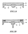
- An actuator consisting of a piezoceramic and one by means of a suspension device 12 on the piezoceramic 10 attached plunger 14, is in Figs. 1A and 1B shown.
- the piezoceramic 10 serves as the actual drive.
- At the piezoceramic 10 is in the usual way on electrodes (not shown) attached thereto a voltage can be created.
- a micromechanically structured is on the piezoceramic 10 Chip 16 attached.
- the chip is a preferred one Embodiment of the present invention, a semiconductor chip.
- the micromechanically structured chip 16 can manufactured using conventional etching techniques, for example his. Silicon, for example, can be used as the chip material his.
- the chip is firmly connected to the piezoceramic at all edges, while essentially in the middle of the micromechanical structured chips located on the elastic Suspensions 12 attached plunger 14 vertically movable is.
- Tappet is sufficient if the chip at least two of them spaced ends, preferably opposite each other Ends are connected to the piezoceramic, wherein the plunger in an area between those on the piezoceramic attached portions of the chip is arranged.
- the elastic suspensions 12 can consist of a membrane, in the bushings 18 for pressure equalization can be arranged.
- the elastic suspensions can however, also consist of individual strips that make up the plunger 14 with the part of the micromechanically attached to the piezoceramic connect structured chips 16.
- the micromechanically manufactured chip has one border 20 extending away from the piezoceramic 10, that for fastening the actuator to a valve body can serve.
- FIG. 1A shows the state of the actuator, if no voltage is applied to the piezoceramic 10 is. If an electrical voltage is applied to the piezoceramic, the piezoceramic 10 reduces its lateral extent. This is due to the parallel to the piezoceramic arrows in the figures, for example in Fig. 1B. The one along the edge of the piezoceramic 10 micromechanically structured connected to the same Chip 16 is compressed, the plunger 14 due to that occurring in the micromechanically structured chip 16 lateral compressive stress tends to become vertical Moving direction. This is indicated by the arrow in Fig. 1B displayed.
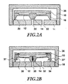
- 2A and 2B is a first embodiment of a Micro valve shown according to the present invention. It is a 2-2-NO microvalve that two ways, i.e. two openings, and two switching states has, the microvalve in the deactivated state is open.
- 2A and 2B Embodiment of the microvalve according to the invention are the valve openings 30 and 32 in one Base plate 34, which consists for example of ceramic. The Base plate 34 can also be used for electrical Serve contacting.
- Fluid connections (not shown) attached, for example a consumer connection and a pressure connection.
- a microstructured plunger chip is on the base plate 34 16, which corresponds to the chip in this exemplary embodiment, 1A and 1B, along its border, i.e. along the lip 20, attached, such that the plunger 14 in the middle of the micromechanical structured chips 16 is freely movable.
- On the micromechanical structured chip 16 is also as referenced 1A and 1B, a piezoceramic 10 attached.
- the side of the base plate 34 facing the Ram 14 is opposite the surface of the base plate 34 reset something. This will increase the height of the valve opening Are defined.
- FIGS. 2A and 2B is the chip edge facing the base plate 34, i.e. the surface of the lip 20 which is attached to the base plate 34 is very narrow, which is a tension-free Rotation of the plunger chip enables.
- On the base plate 34 is also a in the illustrated embodiment Housing cover 36 attached, which is an encapsulation for the The structure described above provides and also as a gas guide can be used.
- FIG. 2B The in Fig. Arrows 37 and 37 'shown in FIG. 2B also represent the near stress-free rotatability of the plunger chip, which is caused by the narrow mounting surface of the microstructured Tappet chips on the base plate 34 is guaranteed.
- the opening of the valve can be supported, or alternatively the closing of it, resulting in an improved Leakage rate behavior results.
- FIG. 3 is a second embodiment of the present Invention shown.
- it is a 2/2-NG valve that has two ways and two Has switching states and closed in the deactivated state is.
- Fig. 3 is in turn a micromechanically structured one Tappet chip 38 attached to a piezoceramic 40.
- the Tappet chip 38 in turn has a tappet 42 which over an elastic suspension 44 on one along the circumference of the plunger chip connected to the piezoceramic part 40 of the plunger chip 38 is attached.
- the assembly of the plunger chip in this case, the piezoceramic 40 takes place in such a way that the valve lifter 42 already with the assembly process a certain mechanical preload is applied, and rests on the valve seat, thereby the valve seat is closed.
- the embodiment shown in Fig. 3 again has a base plate made, for example, of ceramic 48, which has two valve openings 50 and 52, and one Housing cover 54 on.
- the piezoceramic 40 also has two passage openings 56 and 58 on.
- the piezoceramic 40 is via a fastening device, which, however, is a lateral expansion and contraction of the piezoceramic, with the base plate 48 in this way connected that the valve opening 50 of the base plate 48 with the passage opening 56 of the piezoceramic 40 fluidly connected and that the valve opening 52 of the base plate 48 connected to the passage opening 58 of the piezoceramic 40 is.
- FIG. 4 A third embodiment of a microvalve according to the present invention is shown in FIG.
- the elastic Suspensions through which the plunger 62 on the at Piezoceramic 40 attached part of the plunger chip 60 attached has fluid feedthroughs that are exemplary are shown as interruptions 64.
- the micromechanically structured plunger chip 60 in turn has an edge tab 66 on which in the third embodiment the present invention a further valve seat 68 is arranged.
- the valve seat 68 has one Feed-through opening 70.
- the through opening 70 is fluidly with a through opening 72 one of those described Structure encapsulating housing cover 74 connected.
- the arrows 75 and 75 'in Fig. 4 in turn is almost tension-free rotatability due to the narrow upper Area of the edge nose 66 is guaranteed to be displayed.
- the microvalve shown in Fig. 4 can be used as a 3/2-way valve be designated.
- a valve has 3 ways and 2 switching states. With such a valve naturally requires a second valve seat. This is with the illustrated embodiment from another Chip, for example ceramic, silicon or the like, educated.
- the plunger chip is complete along its entire circumference with both the piezoceramic and the second Valve seat connected because of the space between the chip and the piezoceramic and the space between the chip and the second valve seat fluid is guided.
- valve opening is 50 closed in the relaxed state of the piezoceramic 40. If a voltage is now applied to the piezoceramic 40 applied, the longitudinal extent of the same decreases, whereby causes a vertical movement of the plunger 62 upwards becomes. The plunger 62 thereby closes the passage opening 70 in the second valve seat 68 and thus the opening 72 in the Housing cover 74.
- 3/2-way valves are mostly used in the Normal-closed mode operated, so are without pending Energy supply closed. This is why it is advantageous in the assembly process on the valve lifter applied preload so high that the plunger remains on the valve seat even when pressurized from below and the valve remains closed.
- the present invention also includes microvalves, which differ in terms of their structure, the arrangement of the passage openings, etc. from the described embodiments distinguish, as long as with these micro valves actuation of the valve lifter according to the invention is used.
- the present invention thus provides microvalves that with a relatively small size, relatively large passage openings enable. Furthermore, the invention Micro valves manufacture the same using a Full wafer connection technology common in semiconductor technology. The microvalves according to the invention thus face each other known microvalves advantages in terms of simplicity the production as well as a cost saving at the same.
- FIGS. 5A, 5B and 6 are below a fifth and a sixth embodiment of a microvalve according to the present invention. there are the same for the same parts as in FIGS. 1 to 4 Reference numerals used, these parts not again be described separately.
- FIGS. 5A and 5B differs from that in Figs. 2A and 2B represented micro valve in that the micromechanically manufactured chip 100 now has a wider edge tab 102, in the surface facing away from the base body 34 a recess 104 is provided. Through this recess along with the recess created by the training the suspension device and the plunger is defined, a web 106 is defined which interacts with the edge nose 102, to define a swivel.
- Arrows 108 and 108 'in Fig. 5B show how this is provided a swivel at the attachment points of the suspension device 12 on the base body 34 a stress-free Rotation of the ram chip 100, i.e. the suspension device 12, and thus a tension-free opening and closing the opening 30 of the base plate.
- Swivel can be circumferential at a plurality of locations be provided around the plunger chip 100.
- the plunger chip 100 is not all around Connected to the circumference of the base plate 34 must only be guaranteed be that the opening 30 and 32 a fluidic connection have when the opening 30 is open.
- the Ram chip 100 can be made of silicon, for example, while the housing 36 consist of plastic, for example can.
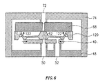
- FIG. 6 is a sixth embodiment of the present Invention shown, which is essentially referring to corresponds to the embodiment described in FIG. 4, where in turn the attachment of the plunger chip 120 on the base plate 68 is different. Again it is Tappet chip 120 attached to the base plate 68 like a hinge, the tension-free rotatability of the plunger chip 120 indicated by arrows 122 and 122 'in Fig. 6 is. The design of the swivel-like attachment again corresponds to that shown in FIGS. 5A and 5B.
Landscapes
- Engineering & Computer Science (AREA)
- General Engineering & Computer Science (AREA)
- Mechanical Engineering (AREA)
- Chemical & Material Sciences (AREA)
- Dispersion Chemistry (AREA)
- Theoretical Computer Science (AREA)
- Physics & Mathematics (AREA)
- Fluid Mechanics (AREA)
- Computer Hardware Design (AREA)
- Microelectronics & Electronic Packaging (AREA)
- Electrically Driven Valve-Operating Means (AREA)
Claims (16)
- Microsoupape, aux caractéristiques suivantes :un corps de base (34 ; 68) avec une ouverture de passage (30 ; 50);un poussoir (14 ; 42 ; 62) ;un dispositif de suspension (12 ; 44) par lequel le poussoir (14; 42; 62) peut être guidé par rapport au corps de base (34; 68) de telle sorte que l'ouverture de passage (30; 70) puisse être obturée ou dégagée par le poussoir (14 ; 42; 62); etun dispositif d'actionnement piézo-électrique (10; 40) destiné à actionner le poussoir (14; 42 ; 62), dont l'extension dans le sens longitudinal peut être modifiée par l'application d'une tension électrique,des extrémités du dispositif d'actionnement piézo-électrique (10; 40), distantes l'une de l'autre dans le sens longitudinal, étant reliées à des extrémités du dispositif de suspension (12; 44), distantes l'une de l'autre dans le sens longitudinal, de sorte que le dispositif de suspension (12; 44) constitue un moyen de fourniture d'une transmission mécanique entre le dispositif d'actionnement (10 ; 40) et le poussoir (14 ; 42 ; 62),une modification de l'extension du dispositif d'actionnement piézo-électrique (10; 40) dans le sens longitudinal provoquée par l'application d'une tension électrique sur le dispositif d'actionnement piézo-électrique (10; 40) étant convertie mécaniquement par le dispositif de suspension (12 ; 44) en un déplacement du poussoir (14; 42; 62) sensiblement perpendiculaire au sens longitudinal, afin de dégager ou d'obturer ainsi l'ouverture de passage (30 ; 70), etle dispositif de suspension (12; 44) étant, en au moins deux points de celui-ci distants l'un de l'autre, fixé au corps de base (34; 68) par des aménagements en forme d'articulation rotative.
- Microsoupape suivant la revendication 1, dans laquelle le dispositif de suspension (12; 44) et le poussoir (14; 42; 62) sont formés d'une seule pièce à partir d'une puce structurée par procédé micromécanique (16 ; 38 ; 60 ; 100; 120).
- Microsoupape suivant la revendication 2, dans laquelle la puce structurée par procédé micromécanique est une puce à semi-conducteur.
- Microsoupape suivant la revendication 2, dans laquelle la puce structurée par procédé micromécanique est réalisée en matière synthétique.
- Microsoupape suivant l'une des revendications 2 à 4, dans laquelle la puce structurée par procédé micromécanique (16 ; 38; 60; 100 ; 120) est assemblée sur son pourtour, sur au moins deux segments distants l'un de l'autre, avec le dispositif d'actionnement piézo-électrique (10 ; 40), présente une ou une pluralité de zones amincies (12 ; 44) représentant le dispositif de suspension, et présentant une zone épaissie (14 ; 42 ; 62) disposée entre les deux extrémités de la puce assemblées avec le dispositif d'actionnement piézo-électrique (10; 40) et constituant le poussoir.
- Microsoupape suivant l'une des revendications 2 à 5, dans laquelle la puce structurée par procédé micromécanique (16; 60) présente un rebord (20) faisant saillie, sur au moins deux segments distants l'un de l'autre sur le pourtour de cette dernière, par rapport au côté éloigné du dispositif d'actionnement piézo-électrique (10), la puce structurée par procédé micromécanique étant fixée au corps de base (34; 68) à l'aide du rebord (20).
- Microsoupape suivant l'une des revendications 1 à 5, dans laquelle le dispositif de suspension est placé sur le corps de base (34 ; 68) à l'aide d'au moins une articulation rotative (102, 106).
- Microsoupape suivant l'une des revendications 1 à 7, dans laquelle le poussoir (14) laisse l'ouverture de passage (30) ouverte lorsqu'il n'est pas appliqué de tension électrique sur le dispositif d'actionnement piézo-électrique (10), et obture l'ouverture de passage (30) lorsqu'une tension électrique est appliquée sur le dispositif d'actionnement piézo-électrique (10).
- Microsoupape suivant la revendication 6, dans laquelle le corps de base (34) présente une seconde ouverture de passage (32) disposée dans une zone du corps de base (34) déterminée par le rebord (20) de la puce structurée par procédé micromécanique (16).
- Microsoupape suivant l'une des revendications 1 à 7, dans laquelle le poussoir (42; 62) obture l'ouverture de passage (50) lorsqu'il n'est pas appliqué de tension électrique sur le dispositif d'actionnement piézo-électrique (40), et laisse l'ouverture de passage (50) ouverte lorsqu'une tension électrique est appliquée sur le dispositif d'actionnement piézo-électrique (40).
- Microsoupape suivant l'une des revendications 1 à 7, dans laquelle le dispositif d'actionnement piézo-électrique (40) est placé sur un élément du boítier (48), par un dispositif de fixation, du côté éloigné du poussoir (62) et du dispositif de suspension, le dispositif d'actionnement (40) présentant, par ailleurs, au moins un trou de passage (56) en communication de fluide, par l'intermédiaire du dispositif de fixation, avec un trou de passage (50) dans l'élément de boítier, le poussoir obturant, dans une première position extrême, le trou de passage (56) dans le dispositif d'actionnement piézo-électrique (40) et obturant, dans une seconde position extrême, le trou de passage (70) dans le corps de base (68), le poussoir (62) pouvant être déplacé, par l'application ou l'élimination d'une tension sur le dispositif d'actionnement piézo-électrique (40), à la première et la seconde position d'extrémité.
- Microsoupape, aux caractéristiques suivantes :un corps de base (48) avec une ouverture de passage (50);un poussoir (42) ;un dispositif de suspension (44) par lequel le poussoir (42) peut être guidé par rapport au corps de base (48) de telle sorte que l'ouverture de passage (50) puisse être obturée ou dégagée par le poussoir (42) ; etun dispositif d'actionnement piézo-électrique (40) destiné à actionner le poussoir (42), dont l'extension dans le sens longitudinal peut être modifiée par l'application d'une tension électrique,le poussoir (42) obturant l'ouverture de passage (50) lorsqu'il n'est pas appliqué de tension électrique sur le dispositif d'actionnement piézo-électrique (40), et laissant l'ouverture de passage (50) ouverte lorsqu'une tension électrique est appliquée sur le dispositif d'actionnement piézo-électrique (40),le dispositif d'actionnement piézo-électrique (40) étant placé, à l'aide d'un dispositif de fixation, sur le côté du corps de base (48) éloigné du poussoir (42) et du dispositif de suspension (44), le dispositif d'actionnement piézo-électrique (40) présentant au moins un trou de passage (56) en communication de fluide, par l'intermédiaire du dispositif de fixation, avec le trou de passage (50) dans le corps de base (48), et le poussoir (42) obturant le trou de passage (50) du corps de base (48) en obturant le trou de passage (58) du dispositif d'actionnement (40),des extrémités du dispositif d'actionnement piézo-électrique (40), distantes l'une de l'autre dans le sens longitudinal, étant reliées à des extrémités du dispositif de suspension (44), distantes l'une de l'autre dans le sens longitudinal, de sorte que le dispositif de suspension (44) constitue un moyen de fourniture d'une transmission mécanique entre le dispositif d'actionnement (40) et le poussoir (42),une modification de l'extension du dispositif d'actionnement piézo-électrique (40) dans le sens longitudinal provoquée par l'application d'une tension électrique sur le dispositif d'actionnement piézo-électrique (40) étant convertie mécaniquement par le dispositif de suspension (12 ; 44) en un déplacement du poussoir (42) sensiblement perpendiculaire au sens longitudinal, afin de dégager ou d'obturer ainsi l'ouverture de passage (50).
- Microsoupape suivant la revendication 12, dans laquelle le dispositif de suspension (44) et le poussoir (42) sont formés d'une seule pièce à partir d'une puce structurée par procédé micromécanique (38).
- Microsoupape suivant la revendication 12 ou 13, dans laquelle la puce structurée par procédé micromécanique est une puce à semi-conducteur.
- Microsoupape suivant la revendication 12 ou 13, dans laquelle la puce structurée par procédé micromécanique est réalisée en matière plastique.
- Microsoupape suivant l'une des revendications 13 à 15, dans laquelle la puce structurée par procédé micromécanique (16 ; 38; 60) est assemblée sur son pourtour, sur au moins deux segments distants l'un de l'autre, avec le dispositif d'actionnement piézo-électrique (10 ; 40), présente une ou une pluralité de zones amincies (12 ; 44) représentant le dispositif de suspension, et présentant une zone épaissie (14; 42; 62) disposée entre les deux extrémités de la puce (16; 38 ; 60) assemblées avec le dispositif d'actionnement piézo-électrique (10 ; 40) et constituant le poussoir.
Applications Claiming Priority (5)
| Application Number | Priority Date | Filing Date | Title |
|---|---|---|---|
| DE1996148730 DE19648730C2 (de) | 1996-11-25 | 1996-11-25 | Piezoelektrisch betätigtes Mikroventil |
| DE19648730 | 1996-11-25 | ||
| DE19735156 | 1997-08-13 | ||
| DE1997135156 DE19735156C1 (de) | 1996-11-25 | 1997-08-13 | Piezoelektrisch betätigtes Mikroventil |
| PCT/EP1997/006344 WO1998023868A1 (fr) | 1996-11-25 | 1997-11-13 | Micro soupape a actionnement piezo-electrique |
Publications (2)
| Publication Number | Publication Date |
|---|---|
| EP0914563A1 EP0914563A1 (fr) | 1999-05-12 |
| EP0914563B1 true EP0914563B1 (fr) | 2001-05-23 |
Family
ID=26031586
Family Applications (1)
| Application Number | Title | Priority Date | Filing Date |
|---|---|---|---|
| EP97951192A Expired - Lifetime EP0914563B1 (fr) | 1996-11-25 | 1997-11-13 | Micro soupape a actionnement piezo-electrique |
Country Status (5)
| Country | Link |
|---|---|
| US (1) | US6131879A (fr) |
| EP (1) | EP0914563B1 (fr) |
| JP (1) | JP2000507681A (fr) |
| DE (2) | DE19735156C1 (fr) |
| WO (1) | WO1998023868A1 (fr) |
Cited By (1)
| Publication number | Priority date | Publication date | Assignee | Title |
|---|---|---|---|---|
| WO2010122016A1 (fr) | 2009-04-24 | 2010-10-28 | Hubert Lachner | Entraînement piézo-électrique et microvalve dotée de ce dernier |
Families Citing this family (54)
| Publication number | Priority date | Publication date | Assignee | Title |
|---|---|---|---|---|
| DE19844518A1 (de) * | 1998-09-28 | 2000-04-06 | Sebastian Pobering | Hydraulischer Wegverstärker für Mikrosysteme |
| WO2000074532A1 (fr) * | 1999-06-07 | 2000-12-14 | Mccord Winn Textron Inc. | Module de commande d'une microsoupape destine a un support moulant le dos de facon pneumatique |
| US6836056B2 (en) | 2000-02-04 | 2004-12-28 | Viking Technologies, L.C. | Linear motor having piezo actuators |
| WO2001067431A1 (fr) | 2000-03-07 | 2001-09-13 | Viking Technologies, Inc. | Procede et systeme d'accord automatique d'un instrument a cordes |
| US6548938B2 (en) * | 2000-04-18 | 2003-04-15 | Viking Technologies, L.C. | Apparatus having a pair of opposing surfaces driven by a piezoelectric actuator |
| US6717332B2 (en) | 2000-04-18 | 2004-04-06 | Viking Technologies, L.C. | Apparatus having a support structure and actuator |
| US6494433B2 (en) * | 2000-06-06 | 2002-12-17 | The Regents Of The University Of Michigan | Thermally activated polymer device |
| DE10048376C2 (de) * | 2000-09-29 | 2002-09-19 | Fraunhofer Ges Forschung | Mikroventil mit einem normalerweise geschlossenen Zustand |
| US6879087B2 (en) | 2002-02-06 | 2005-04-12 | Viking Technologies, L.C. | Apparatus for moving a pair of opposing surfaces in response to an electrical activation |
| US6759790B1 (en) | 2001-01-29 | 2004-07-06 | Viking Technologies, L.C. | Apparatus for moving folded-back arms having a pair of opposing surfaces in response to an electrical activation |
| US6830229B2 (en) * | 2001-05-22 | 2004-12-14 | Lockheed Martin Corporation | Two-stage valve suitable as high-flow high-pressure microvalve |
| DE20116520U1 (de) | 2001-10-09 | 2001-12-20 | FESTO AG & Co., 73734 Esslingen | Ventilglied und damit ausgestattetes Mikroventil |
| DE20116898U1 (de) * | 2001-10-15 | 2002-01-17 | FESTO AG & Co., 73734 Esslingen | Mikroventil |
| US7025324B1 (en) * | 2002-01-04 | 2006-04-11 | Massachusetts Institute Of Technology | Gating apparatus and method of manufacture |
| DE10202996A1 (de) * | 2002-01-26 | 2003-08-14 | Eppendorf Ag | Piezoelektrisch steuerbare Mikrofluidaktorik |
| US6981518B2 (en) * | 2002-03-15 | 2006-01-03 | Cytonome, Inc. | Latching micro-regulator |
| DE10218280C1 (de) * | 2002-04-19 | 2003-11-20 | Fraunhofer Ges Forschung | Integriertes Misch- und Schaltsystem für die Mikroreaktionstechnik |
| USD483335S1 (en) | 2002-06-19 | 2003-12-09 | Viking Technologies, L.C. | Integral actuator with folded-back arms |
| USD493416S1 (en) | 2002-06-19 | 2004-07-27 | Viking Technologies, L.C. | Integral actuator with force transfer member |
| USD494923S1 (en) | 2002-06-19 | 2004-08-24 | Viking Technologies, L.C. | Integral force transfer member |
| US6924586B2 (en) * | 2002-06-21 | 2005-08-02 | Viking Technologies, L.C. | Uni-body piezoelectric motor |
| US6883774B2 (en) * | 2002-10-21 | 2005-04-26 | Lockheed Martin Corporation | Microelectromechanical high pressure gas microvalve |
| USD496330S1 (en) | 2002-12-10 | 2004-09-21 | Viking Technologies, L.C. | Integral actuator with hollowed out force transfer member |
| USD493417S1 (en) | 2002-12-10 | 2004-07-27 | Viking Technologies, L.C. | Folded back arm actuator |
| USD493135S1 (en) | 2002-12-10 | 2004-07-20 | Viking Technologies, L.C. | Integral actuator with folded back arms and hollowed out force transfer member |
| US7368856B2 (en) | 2003-04-04 | 2008-05-06 | Parker-Hannifin Corporation | Apparatus and process for optimizing work from a smart material actuator product |
| JP4344164B2 (ja) * | 2003-04-18 | 2009-10-14 | 株式会社サタケ | 圧電式エアバルブおよび複合圧電式エアバルブ |
| USD512085S1 (en) | 2003-06-06 | 2005-11-29 | Viking Technologies, L.C. | Folded back arm actuator with enlarged central anvil |
| SE0301637D0 (sv) * | 2003-06-06 | 2003-06-06 | Wouter Van Der Wijngaart Royal | a micromachined knife gate valve for high-flow pressure regulation applications |
| DE20313727U1 (de) * | 2003-09-04 | 2005-01-13 | Thinxxs Gmbh | Piezoaktor |
| ATE373795T1 (de) * | 2004-10-28 | 2007-10-15 | Fiat Ricerche | Ventil |
| US20080304979A1 (en) * | 2004-12-23 | 2008-12-11 | Submachine Corp. | Reaction Drive Energy Transfer Device |
| DE102005062554A1 (de) * | 2005-12-27 | 2007-07-05 | Robert Bosch Gmbh | Mikromechanisches Bauelement mit Kappe mit Verschluss |
| FI119708B (fi) | 2006-02-01 | 2009-02-13 | Viconsys Oy | Laite rainan tarkkailemiseksi |
| US7505110B2 (en) * | 2006-03-14 | 2009-03-17 | International Business Machines Corporation | Micro-electro-mechanical valves and pumps |
| WO2009000284A1 (fr) * | 2007-06-22 | 2008-12-31 | Siemens Aktiengesellschaft | Microvanne |
| US8016260B2 (en) * | 2007-07-19 | 2011-09-13 | Formulatrix, Inc. | Metering assembly and method of dispensing fluid |
| US7823436B2 (en) | 2008-01-18 | 2010-11-02 | Pivotal Systems Corporation | Method and apparatus for in situ testing of gas flow controllers |
| DE102008017963B4 (de) * | 2008-04-08 | 2016-10-06 | Airbus Defence and Space GmbH | Strömungssteuerungsbauelement |
| DE102009007317A1 (de) * | 2009-02-03 | 2010-08-12 | Continental Automotive Gmbh | Ventil |
| KR101638489B1 (ko) | 2009-06-04 | 2016-07-11 | 애버리 데니슨 코포레이션 | 열 및/또는 스팀 작동 밸브 및 그것을 위한 방법 |
| TWI435196B (zh) | 2009-10-15 | 2014-04-21 | 派伏塔系統公司 | 氣體流量控制方法及裝置 |
| KR20120015593A (ko) * | 2010-08-12 | 2012-02-22 | 삼성전자주식회사 | 마이크로 밸브를 갖는 미세 유체 소자 |
| US9400004B2 (en) | 2010-11-29 | 2016-07-26 | Pivotal Systems Corporation | Transient measurements of mass flow controllers |
| JP5764049B2 (ja) * | 2011-12-13 | 2015-08-12 | 株式会社サタケ | 圧電式バルブ及び該圧電式バルブを利用した噴風手段を備える光学式粒状物選別機 |
| WO2013157548A1 (fr) * | 2012-04-20 | 2013-10-24 | 株式会社サタケ | Soupape piézoélectrique, et trieur optique de matières particulaires doté d'un moyen de soufflage d'air qui utilise la soupape piézoélectrique |
| US9689508B2 (en) | 2012-08-09 | 2017-06-27 | Zhejiang Dunan Artificial Environment Co., Ltd. | Microvalve device and fluid flow control method |
| US20160046368A1 (en) * | 2013-03-25 | 2016-02-18 | Airi Re Srl Unipersonale | System for operating helicopter blades with compressed air |
| EP3320408A1 (fr) | 2015-07-10 | 2018-05-16 | Pivotal Systems Corporation | Procédé et appareil de contrôle d'écoulement gazeux |
| DE102016205620A1 (de) * | 2016-04-05 | 2017-10-05 | Airbus Defence and Space GmbH | Aktuator-Anordnung |
| US10502327B1 (en) * | 2016-09-23 | 2019-12-10 | Facebook Technologies, Llc | Co-casted fluidic devices |
| US10364909B2 (en) * | 2017-08-18 | 2019-07-30 | GM Global Technology Operations LLC | Fluid flow control device and system |
| TWI646261B (zh) * | 2017-09-15 | 2019-01-01 | 研能科技股份有限公司 | 氣體輸送裝置 |
| US11879567B2 (en) * | 2021-09-10 | 2024-01-23 | New Scale Technologies, Inc. | Microvalve using near-field-acoustic levitation and methods thereof |
Family Cites Families (13)
| Publication number | Priority date | Publication date | Assignee | Title |
|---|---|---|---|---|
| US3174716A (en) * | 1962-10-15 | 1965-03-23 | Salter Jack Nelson | Magnetostrictive multiplier device |
| US4450375A (en) * | 1982-11-12 | 1984-05-22 | Kiwi Coders Corporation | Piezoelectric fluid control device |
| US4581624A (en) * | 1984-03-01 | 1986-04-08 | Allied Corporation | Microminiature semiconductor valve |
| DE3570319D1 (en) * | 1984-07-24 | 1989-06-22 | Siemens Ag | Piezoelectric relay |
| FR2642812B1 (fr) * | 1989-02-08 | 1991-05-31 | Crouzet Sa | Dispositif de commutation de fluide, piezoelectrique a commande optique |
| JP2738054B2 (ja) * | 1989-09-18 | 1998-04-08 | 横河電機株式会社 | マイクロバルブ |
| US5333831A (en) * | 1993-02-19 | 1994-08-02 | Hewlett-Packard Company | High performance micromachined valve orifice and seat |
| US5340081A (en) * | 1993-06-07 | 1994-08-23 | The United States Of America As Represented By The United States Department Of Energy | Means for positively seating a piezoceramic element in a piezoelectric valve during inlet gas injection |
| JPH07158757A (ja) | 1993-12-06 | 1995-06-20 | Nippondenso Co Ltd | マイクロバルブ |
| DE4417251A1 (de) * | 1994-05-17 | 1995-11-23 | Bosch Gmbh Robert | Druckausgeglichenes Mikroventil |
| US5529279A (en) * | 1994-08-24 | 1996-06-25 | Hewlett-Packard Company | Thermal isolation structures for microactuators |
| EP0704916B1 (fr) * | 1994-09-29 | 1999-08-04 | Nec Corporation | Dispositif de serrage piézoélectrique à mouvement amplifié |
| US5927325A (en) * | 1996-10-25 | 1999-07-27 | Inpod, Inc. | Microelectromechanical machined array valve |
-
1997
- 1997-08-13 DE DE1997135156 patent/DE19735156C1/de not_active Expired - Lifetime
- 1997-11-13 US US09/308,543 patent/US6131879A/en not_active Expired - Fee Related
- 1997-11-13 DE DE59703609T patent/DE59703609D1/de not_active Expired - Fee Related
- 1997-11-13 EP EP97951192A patent/EP0914563B1/fr not_active Expired - Lifetime
- 1997-11-13 JP JP52421497A patent/JP2000507681A/ja active Pending
- 1997-11-13 WO PCT/EP1997/006344 patent/WO1998023868A1/fr not_active Ceased
Cited By (3)
| Publication number | Priority date | Publication date | Assignee | Title |
|---|---|---|---|---|
| WO2010122016A1 (fr) | 2009-04-24 | 2010-10-28 | Hubert Lachner | Entraînement piézo-électrique et microvalve dotée de ce dernier |
| DE102009002631A1 (de) | 2009-04-24 | 2010-11-04 | Michael Förg | Piezoelektrischer Antrieb und Mikroventil mit einem solchen |
| DE102009002631B4 (de) * | 2009-04-24 | 2015-08-20 | Michael Förg | Piezoelektrischer Antrieb und Mikroventil mit einem solchen |
Also Published As
| Publication number | Publication date |
|---|---|
| JP2000507681A (ja) | 2000-06-20 |
| EP0914563A1 (fr) | 1999-05-12 |
| US6131879A (en) | 2000-10-17 |
| DE19735156C1 (de) | 1999-04-29 |
| DE59703609D1 (de) | 2001-06-28 |
| WO1998023868A1 (fr) | 1998-06-04 |
Similar Documents
| Publication | Publication Date | Title |
|---|---|---|
| DE19735156C1 (de) | Piezoelektrisch betätigtes Mikroventil | |
| EP0914564B1 (fr) | Microsoupape a actionnement piezo-electrique | |
| EP0700485B1 (fr) | Microvanne | |
| EP0649501B1 (fr) | Micro-soupape | |
| DE4422942B4 (de) | Vorrichtung für den Antrieb eines Mikroventils | |
| EP0478565B1 (fr) | Micro-soupape | |
| EP0741248B1 (fr) | Elément de commande fluidique | |
| AT407432B (de) | Piezoelektrisches ventil | |
| DE10048376A1 (de) | Mikroventil mit einem normalerweise geschlossenen Zustand | |
| EP0686235A1 (fr) | Dispositif de dosage de fluides | |
| DE19546181A1 (de) | Mikroventil | |
| DE4138491A1 (de) | Mikromechanisches ventil fuer mikromechanische dosiereinrichtungen | |
| EP0829649B1 (fr) | Structure de clapet de soupape precontrainte pour une microsoupape | |
| WO1997014902A1 (fr) | Soupape de commande actionnee par un actionneur piezo-electrique | |
| EP1899634B1 (fr) | Dispositif a soupape | |
| EP1306598B1 (fr) | Microvalve | |
| EP1008765A2 (fr) | Actionneur à structure micromécanique et microsoupape | |
| DE102006006706A1 (de) | Mikroventil | |
| DE69918067T2 (de) | Piezo-ventil mit hohem ansprechverhalten | |
| DE102008001153A1 (de) | Absperrorgan | |
| DE102013105557B4 (de) | Piezoelektrischer Aktor | |
| DE4422945C2 (de) | Ventil | |
| DE102009033780B4 (de) | Pneumatikventil | |
| DE10115164C1 (de) | Kraftstoff-Injektor für Einspritzanlagen | |
| EP1357321A1 (fr) | Soupape piezo-électrique |
Legal Events
| Date | Code | Title | Description |
|---|---|---|---|
| PUAI | Public reference made under article 153(3) epc to a published international application that has entered the european phase |
Free format text: ORIGINAL CODE: 0009012 |
|
| 17P | Request for examination filed |
Effective date: 19990311 |
|
| AK | Designated contracting states |
Kind code of ref document: A1 Designated state(s): CH DE DK FR GB IT LI NL |
|
| GRAG | Despatch of communication of intention to grant |
Free format text: ORIGINAL CODE: EPIDOS AGRA |
|
| 17Q | First examination report despatched |
Effective date: 20000915 |
|
| GRAG | Despatch of communication of intention to grant |
Free format text: ORIGINAL CODE: EPIDOS AGRA |
|
| GRAG | Despatch of communication of intention to grant |
Free format text: ORIGINAL CODE: EPIDOS AGRA |
|
| GRAH | Despatch of communication of intention to grant a patent |
Free format text: ORIGINAL CODE: EPIDOS IGRA |
|
| GRAH | Despatch of communication of intention to grant a patent |
Free format text: ORIGINAL CODE: EPIDOS IGRA |
|
| GRAA | (expected) grant |
Free format text: ORIGINAL CODE: 0009210 |
|
| AK | Designated contracting states |
Kind code of ref document: B1 Designated state(s): CH DE DK FR GB IT LI NL |
|
| PG25 | Lapsed in a contracting state [announced via postgrant information from national office to epo] |
Ref country code: NL Free format text: LAPSE BECAUSE OF FAILURE TO SUBMIT A TRANSLATION OF THE DESCRIPTION OR TO PAY THE FEE WITHIN THE PRESCRIBED TIME-LIMIT Effective date: 20010523 Ref country code: IT Free format text: LAPSE BECAUSE OF FAILURE TO SUBMIT A TRANSLATION OF THE DESCRIPTION OR TO PAY THE FEE WITHIN THE PRESCRIBED TIME-LIMIT;WARNING: LAPSES OF ITALIAN PATENTS WITH EFFECTIVE DATE BEFORE 2007 MAY HAVE OCCURRED AT ANY TIME BEFORE 2007. THE CORRECT EFFECTIVE DATE MAY BE DIFFERENT FROM THE ONE RECORDED. Effective date: 20010523 Ref country code: GB Free format text: LAPSE BECAUSE OF FAILURE TO SUBMIT A TRANSLATION OF THE DESCRIPTION OR TO PAY THE FEE WITHIN THE PRESCRIBED TIME-LIMIT Effective date: 20010523 Ref country code: FR Free format text: LAPSE BECAUSE OF FAILURE TO SUBMIT A TRANSLATION OF THE DESCRIPTION OR TO PAY THE FEE WITHIN THE PRESCRIBED TIME-LIMIT Effective date: 20010523 |
|
| REG | Reference to a national code |
Ref country code: CH Ref legal event code: EP |
|
| REF | Corresponds to: |
Ref document number: 59703609 Country of ref document: DE Date of ref document: 20010628 |
|
| PG25 | Lapsed in a contracting state [announced via postgrant information from national office to epo] |
Ref country code: DK Free format text: LAPSE BECAUSE OF FAILURE TO SUBMIT A TRANSLATION OF THE DESCRIPTION OR TO PAY THE FEE WITHIN THE PRESCRIBED TIME-LIMIT Effective date: 20010823 |
|
| NLV1 | Nl: lapsed or annulled due to failure to fulfill the requirements of art. 29p and 29m of the patents act | ||
| GBV | Gb: ep patent (uk) treated as always having been void in accordance with gb section 77(7)/1977 [no translation filed] |
Effective date: 20010523 |
|
| PG25 | Lapsed in a contracting state [announced via postgrant information from national office to epo] |
Ref country code: LI Free format text: LAPSE BECAUSE OF NON-PAYMENT OF DUE FEES Effective date: 20011130 Ref country code: CH Free format text: LAPSE BECAUSE OF NON-PAYMENT OF DUE FEES Effective date: 20011130 |
|
| EN | Fr: translation not filed | ||
| PLBE | No opposition filed within time limit |
Free format text: ORIGINAL CODE: 0009261 |
|
| STAA | Information on the status of an ep patent application or granted ep patent |
Free format text: STATUS: NO OPPOSITION FILED WITHIN TIME LIMIT |
|
| 26N | No opposition filed | ||
| REG | Reference to a national code |
Ref country code: CH Ref legal event code: PL |
|
| PGFP | Annual fee paid to national office [announced via postgrant information from national office to epo] |
Ref country code: DE Payment date: 20040123 Year of fee payment: 7 |
|
| PG25 | Lapsed in a contracting state [announced via postgrant information from national office to epo] |
Ref country code: DE Free format text: LAPSE BECAUSE OF NON-PAYMENT OF DUE FEES Effective date: 20050601 |