EP0914909A2 - Greifvorrichtung. - Google Patents
Greifvorrichtung. Download PDFInfo
- Publication number
- EP0914909A2 EP0914909A2 EP98120412A EP98120412A EP0914909A2 EP 0914909 A2 EP0914909 A2 EP 0914909A2 EP 98120412 A EP98120412 A EP 98120412A EP 98120412 A EP98120412 A EP 98120412A EP 0914909 A2 EP0914909 A2 EP 0914909A2
- Authority
- EP
- European Patent Office
- Prior art keywords
- yoke
- anvil
- movable
- columns
- yokes
- Prior art date
- Legal status (The legal status is an assumption and is not a legal conclusion. Google has not performed a legal analysis and makes no representation as to the accuracy of the status listed.)
- Withdrawn
Links
Images


Classifications
-
- B—PERFORMING OPERATIONS; TRANSPORTING
- B25—HAND TOOLS; PORTABLE POWER-DRIVEN TOOLS; MANIPULATORS
- B25B—TOOLS OR BENCH DEVICES NOT OTHERWISE PROVIDED FOR, FOR FASTENING, CONNECTING, DISENGAGING, OR HOLDING
- B25B5/00—Clamps
- B25B5/16—Details, e.g. jaws, jaw attachments
- B25B5/163—Jaws or jaw attachments
-
- B—PERFORMING OPERATIONS; TRANSPORTING
- B25—HAND TOOLS; PORTABLE POWER-DRIVEN TOOLS; MANIPULATORS
- B25B—TOOLS OR BENCH DEVICES NOT OTHERWISE PROVIDED FOR, FOR FASTENING, CONNECTING, DISENGAGING, OR HOLDING
- B25B1/00—Vices
- B25B1/06—Arrangements for positively actuating jaws
- B25B1/10—Arrangements for positively actuating jaws using screws
- B25B1/103—Arrangements for positively actuating jaws using screws with one screw perpendicular to the jaw faces, e.g. a differential or telescopic screw
-
- B—PERFORMING OPERATIONS; TRANSPORTING
- B25—HAND TOOLS; PORTABLE POWER-DRIVEN TOOLS; MANIPULATORS
- B25B—TOOLS OR BENCH DEVICES NOT OTHERWISE PROVIDED FOR, FOR FASTENING, CONNECTING, DISENGAGING, OR HOLDING
- B25B3/00—Hand vices, i.e. vices intended to be held by hand; Pin vices
-
- B—PERFORMING OPERATIONS; TRANSPORTING
- B25—HAND TOOLS; PORTABLE POWER-DRIVEN TOOLS; MANIPULATORS
- B25B—TOOLS OR BENCH DEVICES NOT OTHERWISE PROVIDED FOR, FOR FASTENING, CONNECTING, DISENGAGING, OR HOLDING
- B25B5/00—Clamps
- B25B5/06—Arrangements for positively actuating jaws
- B25B5/10—Arrangements for positively actuating jaws using screws
- B25B5/102—Arrangements for positively actuating jaws using screws with at least one jaw sliding along a bar
-
- Y—GENERAL TAGGING OF NEW TECHNOLOGICAL DEVELOPMENTS; GENERAL TAGGING OF CROSS-SECTIONAL TECHNOLOGIES SPANNING OVER SEVERAL SECTIONS OF THE IPC; TECHNICAL SUBJECTS COVERED BY FORMER USPC CROSS-REFERENCE ART COLLECTIONS [XRACs] AND DIGESTS
- Y10—TECHNICAL SUBJECTS COVERED BY FORMER USPC
- Y10S—TECHNICAL SUBJECTS COVERED BY FORMER USPC CROSS-REFERENCE ART COLLECTIONS [XRACs] AND DIGESTS
- Y10S269/00—Work holders
- Y10S269/902—Work holder member with v-shaped notch or groove
-
- Y—GENERAL TAGGING OF NEW TECHNOLOGICAL DEVELOPMENTS; GENERAL TAGGING OF CROSS-SECTIONAL TECHNOLOGIES SPANNING OVER SEVERAL SECTIONS OF THE IPC; TECHNICAL SUBJECTS COVERED BY FORMER USPC CROSS-REFERENCE ART COLLECTIONS [XRACs] AND DIGESTS
- Y10—TECHNICAL SUBJECTS COVERED BY FORMER USPC
- Y10S—TECHNICAL SUBJECTS COVERED BY FORMER USPC CROSS-REFERENCE ART COLLECTIONS [XRACs] AND DIGESTS
- Y10S294/00—Handling: hand and hoist-line implements
- Y10S294/902—Gripping element
Definitions
- This invention relates to a gripping or chucking device for accurately, reliably and quickly gripping or chucking small workpieces having irregular shapes to work them.
- chucking surfaces had to be worked so as to be complementary to the contour of the workpiece, or V blocks or liners were used in combination.
- An object of this invention is to provide a gripping device which can reliably grip small articles having different shapes with a single gripping device without the need to work its chucking surfaces to a special shape complementary to the contour of each article or without the need to use in blocks or liners in combination, and which can position articles in parallel to or perpendicularly to an X-Y table of a machine tool.
- a gripping device for gripping small articles having different shapes, comprising a fixed yoke, a movable yoke, an anvil-side yoke and two columns, said two columns extending from said movable yoke to at least one of said fixed yoke and said anvil-side yoke and pivotably coupled thereto by pins rotatably provided at both ends thereof to form a parallel crank mechanism, said fixed yoke having a means for pushing and pulling said movable yoke, said movable yoke and said anvil-side yoke having opposed portions formed with V grooves perpendicularly to said yokes, wherein a plurality of cuts are formed parallel to said yokes at the portion of said V grooves, whereby plate-shaped V-grooved gripping portions mesh with each other.
- a threaded hole 2 is formed in the center of a fixed yoke 1.
- a threaded shaft 6 (having a knob 5 for turning the shaft) threads into the threaded hole 2 to move a movable yoke 3 toward and away from an anvil-side yoke 4.
- a column 8 is pivotally mounted to each end of the fixed yoke 1 by a pin 7.
- Pins 10, 11 extend through the yokes 3 and 4, respectively, at their opposed ends.
- the columns 8 are slidably inserted through holes 9 in the pins 10, 11 formed perpendicularly to their axes.
- the movable yoke 3 for pressing an article to be gripped and the anvil-side yoke 4 for supporting the article are pivotally coupled together by the columns 8 and the pins 10 and 11.
- the distance between the pins 7 of the fixed yoke 1, the distance between the pins 10 of the movable yoke 3, and the distance between the pins 11 of the anvil-side yoke 4 are equal to each other.
- Split pins 12 are inserted in the free ends of the columns 8 to prevent the anvil-side yoke 4 from slipping out of the columns 8.
- V grooves 13 for gripping the article to be gripped are formed in the movable yoke 3 and the anvil-side yoke 4 at their portions facing each other.
- a plurality of cuts 14 (Fig. 1) are formed in the movable yoke 3 and the anvil-side yoke 4 so as to be parallel to each other.
- the cuts 14 define a plurality of plate portions 15 having V-grooved gripping portions 13c.
- the plate portions 15 of the movable yoke 3 are adapted to mesh with those of the anvil-side yoke 4.
- elongate holes 16 and 17 are formed that extend parallel to and perpendicularly to the axes of the pins 10 at both ends of the yoke 3, respectively.
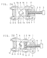
- the tip of the threaded shaft 6 engages in the elongate hole 17 and coupled to the yoke 3 by a snap washer 18 so as to be pivotable within the range permitted by the elongate holes 16, 17.
- the movable yoke 3 is moved toward the anvil-side yoke 4 by turning the threaded shaft 6 to grip the article between two yokes as shown in Fig. 2A.
- the entire device moves parallelogrammatically so that the V-grooved gripping portions 13c define a rectangle as shown in Fig. 2B. The article is thus firmly gripped with its reference surfaces along the surfaces of the V-grooved gripping portions.
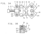
- a block 19 for fixing the gripping device of this embodiment on a machine tool or the like has a substantially L-shaped section formed by cutting a hexahedral block at its one corner in a V shape as shown at 30 (on Fig. 3A), and has knocks 20 embedded in its top surface.
- the gripping device is fixed in position with the bisector of the V-grooved gripping portions aligned with the bisector of the V-shaped cutout in the block 19.
- the block 19 By fixing the block 19 to an X-Y table in this state, the article to be gripped is automatically positioned with its reference surface parallel to the reference surface of the X-Y table.
- the bottom of the V-grooved gripping portion is adapted to protrude from the cut surface. This makes it easier to grip a long article and prevents damage to the block and the cutting tool while a through hole is formed in the workpiece.
- FIG. 3 the second embodiment is described.
- this embodiment is substantially the same as the first embodiment. Thus, only what differs from the first embodiment is described.
- the threaded shaft 6 is pivotally coupled to the movable yoke 3 by the elongate holes 16, 17 formed in the movable yoke 3.
- the threaded shaft 6 is coupled to the movable yoke 3 so as to be rotatable but not pivotable relative to the yoke 3.
- the threaded shaft 6 is rotatably coupled to the yoke 3 by a pin 24 inserted in a cutout 23 formed at its tip.
- the fixed yoke 1 is formed with an elongate hole 28 in which is slidably fitted a female threaded bushing 29 in which the threaded shaft 6 engages.
- a female threaded bushing 29 in which the threaded shaft 6 engages.
- the pins 11 mounted in the anvil-side yoke have holes 9 (see Fig. 2) extending perpendicularly to the pin axes.
- the columns 8 extend through the holes 9.
- a hexagonal screw 22 is screwed into the center of each pin 11 so that a protrusion at its tip engages in a hole 27 formed in each column 8 (Fig. 3B), thus preventing separation.
- the fixed yoke 1 and the columns 8 are also coupled together in a similar manner.
- the gripping device of this embodiment is mounted to the block 19 and positioned by the knocks 20 as in the first embodiment (see Fig. 1).
- a hexagonal screw 25 extends through a hole formed in the center of the anvil-side yoke 4 and into an internally threaded hole formed in the block 19.
- the cut portion 30 is positioned under the V-grooved portion 13c, so that a long article can be gripped easily. This prevents damage to the block and the cutting tool when forming a through hole in the workkpiece.
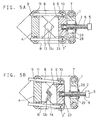
- Fig. 4 is the third embodiment, which is basically the same as the second embodiment except that the positions of the movable yoke 3 and the anvil-side yoke 4 are reversed.
- the anvil-side yoke 4 is movable relative to the columns 8.
- the anvil-side yoke 4 is at the center of the entire gripping device and is mounted to the block 19. This ensures mounting with good balance.
- Fig. 5 shows the fourth embodiment, which is the same as the previous embodiments in that small articles of various shapes are gripped by meshing plate-shaped V-grooved gripping portions 13c defined by a plurality of cuts 14. Thus, only the difference is described below.
- An anvil-side yoke 4 and a fixed yoke 1 are fixed to a base B.
- An elongate hole 28 is formed in the center of the fixed yoke 1.
- a bushing 29 having female threads 2 slidably fits in the elongate hole 28.
- a cut 23 is formed at its tip. It is received in the center of the movable yoke 3 and coupled thereto by an unillustrated pin so as to be pivotable but not to come off.
- the movable yoke 3, the anvil-side yoke 4 and the columns 8 connecting them together constitute a parallel crank mechanism through the pins 10 and 11.
- the threaded shaft 6 By turning the threaded shaft 6, the V-grooved gripping portions 13c of the yokes 3 and 4 are moved toward and away from each other. Small articles having irregular shapes can be gripped efficiently and reliably by the parallelogrammatic movement of the device as shown in Fig. 5B.
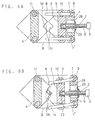
- Fig. 6 shows the fifth embodiment, which is structurally the same as the fourth embodiment except that columns 8 forming a parallel crank mechanism extend from the fixed yoke 1 to the movable yoke 3 and are pivotably coupled to the yokes 1 and 3 by pins 7 and 10, respectively, rotatably provided on both ends of the yokes 1 and 3.
- the fixed yoke 1, movable yoke 3 and columns 8 are parallelogrammatically moved so that the movable yoke 3 is moved toward the anvil side yoke 4 along the columns 8 as shown in Fig. 6B.
- the article can thus be gripped efficiently and reliably.
- Fig. 7 shows the sixth embodiment, which is basically the same as the fifth embodiment except that the columns 8 extend from the movable yoke 3 to the fixed yoke 1.
- the fixed yoke 1, movable yoke 3 and columns 8 are parallelogrammatically moved so that the columns 8 slide in the holes 9 formed in the pins 7 rotatably provided at both ends of the fixed yoke 1. The article can thus be gripped efficiently and reliably.
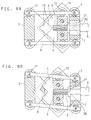
- Fig. 8 shows the seventh embodiment, which is basically the same as the third embodiment except that the anvil-side yoke 4 is formed with a threaded hole 2 into which is threaded a threaded shaft 6 received in an elongated hole 28 formed in the fixed yoke 1 so that the threaded shaft 6 and the fixed yoke 1 are pivotable relative to each other.
- the threaded shaft 6 has a flange 31 and a knob 5 that abut both ends of the fixed yoke 1 to prevent axial movement of the yoke 1 relative to the shaft 6.
- the thrust of the threaded shaft 6 is applied directly on the anvil-side yoke 4 to push and pull it.
- the arrangement of this embodiment is applicable to any of the first to sixth embodiments.
- the threaded shaft 6 is used to push and pull the movable yoke 3.
- the yoke 3 may be pushed and pulled by a cam means, an electromagnetic suction mechanism or a fluid pressure means such as an air cylinder (not shown).
- articles having different shapes can be gripped easily and reliably without working the chucking surfaces or without using V blocks or liners. Further, it is possible to grip a workpiece vertically or with its reference surface aligned with the moving direction of an X-Y table of a machine tool.
Landscapes
- Engineering & Computer Science (AREA)
- Mechanical Engineering (AREA)
- Jigs For Machine Tools (AREA)
- Gripping Jigs, Holding Jigs, And Positioning Jigs (AREA)
- Manipulator (AREA)
- Toys (AREA)
Applications Claiming Priority (9)
| Application Number | Priority Date | Filing Date | Title |
|---|---|---|---|
| JP304517/97 | 1997-11-06 | ||
| JP30451797 | 1997-11-06 | ||
| JP30451797 | 1997-11-06 | ||
| JP50980/98 | 1998-03-03 | ||
| JP5098098 | 1998-03-03 | ||
| JP5098098 | 1998-03-03 | ||
| JP282213/98 | 1998-10-05 | ||
| JP10282213A JP3037665B2 (ja) | 1997-11-06 | 1998-10-05 | 小形異形物の掴持装置 |
| JP28221398 | 1998-10-05 |
Publications (2)
| Publication Number | Publication Date |
|---|---|
| EP0914909A2 true EP0914909A2 (de) | 1999-05-12 |
| EP0914909A3 EP0914909A3 (de) | 2005-05-18 |
Family
ID=27294149
Family Applications (1)
| Application Number | Title | Priority Date | Filing Date |
|---|---|---|---|
| EP98120412A Withdrawn EP0914909A3 (de) | 1997-11-06 | 1998-10-28 | Greifvorrichtung. |
Country Status (4)
| Country | Link |
|---|---|
| US (1) | US6099058A (de) |
| EP (1) | EP0914909A3 (de) |
| JP (1) | JP3037665B2 (de) |
| TW (1) | TW393362B (de) |
Cited By (9)
| Publication number | Priority date | Publication date | Assignee | Title |
|---|---|---|---|---|
| EP0950471A3 (de) * | 1998-04-07 | 2002-11-13 | Kabushiki Kaisha Asai Tekkosho | Greifvorrichtung |
| CN102699703A (zh) * | 2012-06-07 | 2012-10-03 | 珠海格力电器股份有限公司 | 一种钻孔夹具 |
| CN102896510A (zh) * | 2012-09-27 | 2013-01-30 | 苏州市意可机电有限公司 | 一种加工铣削定位装置用加工辅具 |
| US9922458B2 (en) | 2013-11-04 | 2018-03-20 | The University Of British Columbia | Methods and systems for generating polycube segmentations from input meshes of objects |
| US9972128B2 (en) | 2012-07-20 | 2018-05-15 | The University Of British Columbia | Methods and systems for generating polycubes and all-hexahedral meshes of an object |
| US10210657B2 (en) | 2015-07-24 | 2019-02-19 | The University Of British Columbia | Methods and systems for hex-mesh optimization via edge-cone rectification |
| CN110877211A (zh) * | 2019-11-22 | 2020-03-13 | 成都凯天电子股份有限公司 | 装夹薄片工件的多工位浮动夹持器 |
| CN112171329A (zh) * | 2020-09-24 | 2021-01-05 | 侯仕仙 | 一种异形零件机械加工装夹定位装置 |
| CN112677067A (zh) * | 2020-12-09 | 2021-04-20 | 安徽中富磁电有限公司 | 一种用于磁芯固定的可调节夹紧装置 |
Families Citing this family (12)
| Publication number | Priority date | Publication date | Assignee | Title |
|---|---|---|---|---|
| AU2006219107B2 (en) * | 2005-03-02 | 2011-05-12 | Epiroc Rock Drills Aktiebolag | Drill rod support, and drill rod support half |
| ITPD20050216A1 (it) * | 2005-07-12 | 2007-01-13 | Ritmo Spa | Morsa di bloccaggio per tubazioni |
| CN102785177A (zh) * | 2012-09-05 | 2012-11-21 | 苏州天盛电线电缆有限公司 | 电动管子台虎钳 |
| CN103639424B (zh) * | 2013-11-25 | 2016-08-17 | 宁波轴瓦厂 | 一种翻边轴套的精车无边端端面及倒角装置 |
| CN107053044A (zh) * | 2017-03-23 | 2017-08-18 | 无锡市明骥智能机械有限公司 | 适用于活塞杆的实用型夹具 |
| US11548119B2 (en) * | 2018-09-26 | 2023-01-10 | Gerardo Molina | Systems and methods for a dual sided clamp |
| CN111843868B (zh) * | 2020-06-22 | 2021-12-10 | 长沙嘉百精密机械有限公司 | 一种使用并联臂实现异形工件夹持的虎钳 |
| CN113319335A (zh) * | 2021-05-13 | 2021-08-31 | 广州和之诚金属制品有限公司 | 一种加工小孔径内孔的工艺及其设备 |
| CN113460630B (zh) * | 2021-06-16 | 2025-06-24 | 珠海达明科技有限公司 | 一种小型杯状产品翻转搬运装置 |
| WO2023084731A1 (ja) * | 2021-11-12 | 2023-05-19 | 株式会社Braing | ワーククランプ装置 |
| US11925524B1 (en) * | 2023-06-07 | 2024-03-12 | King Faisal University | Dental tooth grasper |
| CN121061390A (zh) * | 2025-11-10 | 2025-12-05 | 南通环球光学仪器有限公司 | 一种光学镜片激光切割机床 |
Family Cites Families (12)
| Publication number | Priority date | Publication date | Assignee | Title |
|---|---|---|---|---|
| FR1006062A (fr) * | 1947-11-06 | 1952-04-18 | Mandrin perfectionné | |
| US2484339A (en) * | 1948-01-02 | 1949-10-11 | Fuhr Henry | Screw-operated vise having vertically adjustable and guided nutblock mounting and guiding a horizontally movable vise jaw |
| US2615682A (en) * | 1951-03-24 | 1952-10-28 | Standard Oil Dev Co | Power-operated slidable jaw pipe tong |
| US3829077A (en) * | 1972-03-27 | 1974-08-13 | Imp Eastman Corp | Adjustable clamping means |
| US4223937A (en) * | 1978-03-17 | 1980-09-23 | Outboard Marine Corporation | Connecting rod cap alignment fixture |
| US4146214A (en) * | 1978-04-18 | 1979-03-27 | Gamble Dansby L | Pipe-gripping vise accessory |
| GB2101506B (en) * | 1981-06-18 | 1985-05-30 | Tekron Licensing Bv | Workbench vices |
| DE3244022C2 (de) | 1982-11-27 | 1985-04-11 | Bessey & Sohn Gmbh & Co, 7000 Stuttgart | Spannvorrichtung zum Fixieren von im Winkel zueinander verlaufenden Werkstücken |
| CH668733A5 (de) * | 1986-02-07 | 1989-01-31 | Buechler B Set Ag | Vorrichtung zur halterung und handhabung eines flachen gegenstandes. |
| US4819978A (en) * | 1986-06-27 | 1989-04-11 | California Institute Of Technology | Grasp force sensor for robotic hands |
| EP0355079B1 (de) * | 1988-08-17 | 1993-02-24 | Gregorio Caceres Serrano | Befestigungswerkzeug |
| DE3831375A1 (de) * | 1988-09-15 | 1990-03-22 | Bessey & Sohn | Spanneinrichtung |
-
1998
- 1998-10-05 JP JP10282213A patent/JP3037665B2/ja not_active Expired - Fee Related
- 1998-10-28 EP EP98120412A patent/EP0914909A3/de not_active Withdrawn
- 1998-11-04 US US09/185,728 patent/US6099058A/en not_active Expired - Fee Related
- 1998-12-03 TW TW087120053A patent/TW393362B/zh not_active IP Right Cessation
Cited By (10)
| Publication number | Priority date | Publication date | Assignee | Title |
|---|---|---|---|---|
| EP0950471A3 (de) * | 1998-04-07 | 2002-11-13 | Kabushiki Kaisha Asai Tekkosho | Greifvorrichtung |
| CN102699703A (zh) * | 2012-06-07 | 2012-10-03 | 珠海格力电器股份有限公司 | 一种钻孔夹具 |
| CN102699703B (zh) * | 2012-06-07 | 2015-11-25 | 珠海格力电器股份有限公司 | 一种钻孔夹具 |
| US9972128B2 (en) | 2012-07-20 | 2018-05-15 | The University Of British Columbia | Methods and systems for generating polycubes and all-hexahedral meshes of an object |
| CN102896510A (zh) * | 2012-09-27 | 2013-01-30 | 苏州市意可机电有限公司 | 一种加工铣削定位装置用加工辅具 |
| US9922458B2 (en) | 2013-11-04 | 2018-03-20 | The University Of British Columbia | Methods and systems for generating polycube segmentations from input meshes of objects |
| US10210657B2 (en) | 2015-07-24 | 2019-02-19 | The University Of British Columbia | Methods and systems for hex-mesh optimization via edge-cone rectification |
| CN110877211A (zh) * | 2019-11-22 | 2020-03-13 | 成都凯天电子股份有限公司 | 装夹薄片工件的多工位浮动夹持器 |
| CN112171329A (zh) * | 2020-09-24 | 2021-01-05 | 侯仕仙 | 一种异形零件机械加工装夹定位装置 |
| CN112677067A (zh) * | 2020-12-09 | 2021-04-20 | 安徽中富磁电有限公司 | 一种用于磁芯固定的可调节夹紧装置 |
Also Published As
| Publication number | Publication date |
|---|---|
| US6099058A (en) | 2000-08-08 |
| JPH11320428A (ja) | 1999-11-24 |
| TW393362B (en) | 2000-06-11 |
| JP3037665B2 (ja) | 2000-04-24 |
| EP0914909A3 (de) | 2005-05-18 |
Similar Documents
| Publication | Publication Date | Title |
|---|---|---|
| US6099058A (en) | Gripping device | |
| US6179279B1 (en) | Gripping device | |
| US5149071A (en) | Double-jaw vice for holding workpieces | |
| CN215036639U (zh) | 柔性工装夹具 | |
| US5623754A (en) | Apparatus for facilitating the detachment of an element from an object | |
| WO2018211868A1 (en) | Workpiece gripping device | |
| US8905691B2 (en) | Arc surface milling assistant processing device | |
| CN112025584A (zh) | 一种用于机械制造的多功能夹具 | |
| JP2001138154A (ja) | バイス | |
| US20070063405A1 (en) | Clamping apparatus with a clamping holder | |
| CN115741529A (zh) | 夹持工装 | |
| US5551676A (en) | Dual clamping vise | |
| KR200320307Y1 (ko) | 공작물의 고정장치 | |
| CN210866145U (zh) | 晶圆定位机构 | |
| KR100560050B1 (ko) | 공작물의 고정장치 | |
| CN216576688U (zh) | 自定心工装夹具 | |
| CN218556754U (zh) | 一种夹持装置 | |
| CN214686073U (zh) | 一种夹持装置 | |
| AU2021221026B2 (en) | Device for mounting a tooling board in a flat bed die-cutting, stripping or blanking machine | |
| WO2022238316A1 (en) | Adaptive and modular fixture and clamping arrangement | |
| CN114670234A (zh) | 定位机构、轴类零件的夹取装置以及安装方法 | |
| CN223589181U (zh) | 一种夹持稳定且夹持快速的工装夹具 | |
| CN211102234U (zh) | 激光切割夹持装置及激光切割机 | |
| CN219684596U (zh) | 夹紧工装 | |
| CN222222428U (zh) | 安装治具 |
Legal Events
| Date | Code | Title | Description |
|---|---|---|---|
| PUAI | Public reference made under article 153(3) epc to a published international application that has entered the european phase |
Free format text: ORIGINAL CODE: 0009012 |
|
| AK | Designated contracting states |
Kind code of ref document: A2 Designated state(s): AT BE CH CY DE DK ES FI FR GB GR IE IT LI LU MC NL PT SE |
|
| AX | Request for extension of the european patent |
Free format text: AL;LT;LV;MK;RO;SI |
|
| 17P | Request for examination filed |
Effective date: 19991103 |
|
| PUAL | Search report despatched |
Free format text: ORIGINAL CODE: 0009013 |
|
| AK | Designated contracting states |
Kind code of ref document: A3 Designated state(s): AT BE CH CY DE DK ES FI FR GB GR IE IT LI LU MC NL PT SE |
|
| AX | Request for extension of the european patent |
Extension state: AL LT LV MK RO SI |
|
| RIC1 | Information provided on ipc code assigned before grant |
Ipc: 7B 25B 5/16 B Ipc: 7B 25B 5/10 A |
|
| AKX | Designation fees paid |
Designated state(s): CH DE FR GB LI SE |
|
| STAA | Information on the status of an ep patent application or granted ep patent |
Free format text: STATUS: THE APPLICATION HAS BEEN WITHDRAWN |
|
| 18W | Application withdrawn |
Effective date: 20060828 |