EP0915252A2 - Système d'injection par alimentation commune des injecteurs - Google Patents
Système d'injection par alimentation commune des injecteurs Download PDFInfo
- Publication number
- EP0915252A2 EP0915252A2 EP98117887A EP98117887A EP0915252A2 EP 0915252 A2 EP0915252 A2 EP 0915252A2 EP 98117887 A EP98117887 A EP 98117887A EP 98117887 A EP98117887 A EP 98117887A EP 0915252 A2 EP0915252 A2 EP 0915252A2
- Authority
- EP
- European Patent Office
- Prior art keywords
- rail
- housing
- injection system
- injectors
- openings
- Prior art date
- Legal status (The legal status is an assumption and is not a legal conclusion. Google has not performed a legal analysis and makes no representation as to the accuracy of the status listed.)
- Withdrawn
Links
- 238000002347 injection Methods 0.000 title claims description 33
- 239000007924 injection Substances 0.000 title claims description 33
- 239000000446 fuel Substances 0.000 title description 5
- 238000002485 combustion reaction Methods 0.000 claims description 31
- 230000004308 accommodation Effects 0.000 abstract description 2
- 238000010276 construction Methods 0.000 description 5
- 230000005540 biological transmission Effects 0.000 description 4
- 230000001105 regulatory effect Effects 0.000 description 4
- 238000003780 insertion Methods 0.000 description 3
- 230000037431 insertion Effects 0.000 description 3
- 230000006835 compression Effects 0.000 description 2
- 238000007906 compression Methods 0.000 description 2
- 238000000034 method Methods 0.000 description 2
- 230000001960 triggered effect Effects 0.000 description 2
- 230000001419 dependent effect Effects 0.000 description 1
- 230000000694 effects Effects 0.000 description 1
- 238000009434 installation Methods 0.000 description 1
- 238000004519 manufacturing process Methods 0.000 description 1
- 239000000463 material Substances 0.000 description 1
- 230000001404 mediated effect Effects 0.000 description 1
- 230000008439 repair process Effects 0.000 description 1
- 238000005096 rolling process Methods 0.000 description 1
- 238000007493 shaping process Methods 0.000 description 1
Images

Classifications
-
- F—MECHANICAL ENGINEERING; LIGHTING; HEATING; WEAPONS; BLASTING
- F02—COMBUSTION ENGINES; HOT-GAS OR COMBUSTION-PRODUCT ENGINE PLANTS
- F02M—SUPPLYING COMBUSTION ENGINES IN GENERAL WITH COMBUSTIBLE MIXTURES OR CONSTITUENTS THEREOF
- F02M39/00—Arrangements of fuel-injection apparatus with respect to engines; Pump drives adapted to such arrangements
-
- F—MECHANICAL ENGINEERING; LIGHTING; HEATING; WEAPONS; BLASTING
- F02—COMBUSTION ENGINES; HOT-GAS OR COMBUSTION-PRODUCT ENGINE PLANTS
- F02M—SUPPLYING COMBUSTION ENGINES IN GENERAL WITH COMBUSTIBLE MIXTURES OR CONSTITUENTS THEREOF
- F02M39/00—Arrangements of fuel-injection apparatus with respect to engines; Pump drives adapted to such arrangements
- F02M39/02—Arrangements of fuel-injection apparatus to facilitate the driving of pumps; Arrangements of fuel-injection pumps; Pump drives
-
- F—MECHANICAL ENGINEERING; LIGHTING; HEATING; WEAPONS; BLASTING
- F02—COMBUSTION ENGINES; HOT-GAS OR COMBUSTION-PRODUCT ENGINE PLANTS
- F02M—SUPPLYING COMBUSTION ENGINES IN GENERAL WITH COMBUSTIBLE MIXTURES OR CONSTITUENTS THEREOF
- F02M55/00—Fuel-injection apparatus characterised by their fuel conduits or their venting means; Arrangements of conduits between fuel tank and pump F02M37/00
- F02M55/02—Conduits between injection pumps and injectors, e.g. conduits between pump and common-rail or conduits between common-rail and injectors
- F02M55/025—Common rails
-
- F—MECHANICAL ENGINEERING; LIGHTING; HEATING; WEAPONS; BLASTING
- F02—COMBUSTION ENGINES; HOT-GAS OR COMBUSTION-PRODUCT ENGINE PLANTS
- F02M—SUPPLYING COMBUSTION ENGINES IN GENERAL WITH COMBUSTIBLE MIXTURES OR CONSTITUENTS THEREOF
- F02M61/00—Fuel-injectors not provided for in groups F02M39/00 - F02M57/00 or F02M67/00
- F02M61/14—Arrangements of injectors with respect to engines; Mounting of injectors
-
- F—MECHANICAL ENGINEERING; LIGHTING; HEATING; WEAPONS; BLASTING
- F02—COMBUSTION ENGINES; HOT-GAS OR COMBUSTION-PRODUCT ENGINE PLANTS
- F02M—SUPPLYING COMBUSTION ENGINES IN GENERAL WITH COMBUSTIBLE MIXTURES OR CONSTITUENTS THEREOF
- F02M63/00—Other fuel-injection apparatus having pertinent characteristics not provided for in groups F02M39/00 - F02M57/00 or F02M67/00; Details, component parts, or accessories of fuel-injection apparatus, not provided for in, or of interest apart from, the apparatus of groups F02M39/00 - F02M61/00 or F02M67/00; Combination of fuel pump with other devices, e.g. lubricating oil pump
- F02M63/02—Fuel-injection apparatus having several injectors fed by a common pumping element, or having several pumping elements feeding a common injector; Fuel-injection apparatus having provisions for cutting-out pumps, pumping elements, or injectors; Fuel-injection apparatus having provisions for variably interconnecting pumping elements and injectors alternatively
- F02M63/0225—Fuel-injection apparatus having a common rail feeding several injectors ; Means for varying pressure in common rails; Pumps feeding common rails
-
- F—MECHANICAL ENGINEERING; LIGHTING; HEATING; WEAPONS; BLASTING
- F02—COMBUSTION ENGINES; HOT-GAS OR COMBUSTION-PRODUCT ENGINE PLANTS
- F02B—INTERNAL-COMBUSTION PISTON ENGINES; COMBUSTION ENGINES IN GENERAL
- F02B3/00—Engines characterised by air compression and subsequent fuel addition
- F02B3/06—Engines characterised by air compression and subsequent fuel addition with compression ignition
Definitions
- the invention relates to a common rail injection system for internal combustion engines.
- Common rail injection systems are used in internal combustion engines, where the combustion medium is used to optimize the combustion performance in the combustion chambers of the individual cylinders should be atomized.
- the combustion medium is in a High pressure pump compressed and on a rail on the injectors of the individual cylinder distributed.
- the electrical signal is transmitted Injection process of the combustion medium into the combustion chamber triggered, with the combustion medium under high pressure through the injectors of the injectors at high speed finely distributed in the combustion chambers of the engine.
- a pump housing High pressure pump is a flange on a motor housing Internal combustion engine attached.
- the high pressure pump works with one Plunger cylinder which, together with a plunger, creates a delivery chamber limited.
- the delivery chamber is with a line for the inflow of the pressure medium connected, which is regulated by a pressure-controlled inlet valve and the plunger cylinder has a passage for the outflow of the pressure medium, which is also controlled by a pressure-controlled valve is regulated on.
- the plunger cylinder is surrounded by a pressure body, whose flow channels follow the passage opening of the plunger cylinder connect outside.
- JP-A-09 060562 discloses an internal combustion engine with direct injection, where a high pressure fuel pump with the cylinder head connected is.
- the cylinder head has a channel inside through which the fuel is pumped away from the high pressure fuel pump becomes.
- the common rail placed on the injection valves is included connected to the cylinder head and has a passage in its interior to distribute the fuel to the injectors.
- a pump housing is created from a plunger cylinder and a piston guide formed for a high pressure pump. This from plunger cylinder and Existing pump housing engages in a suitable piston guide Opening a motor housing in the way that part of the pump housing protrudes from the motor housing and directly on this by means of bolts is attached.
- This construction is also in construction and assembly complex.
- the present invention has set itself the task of a common rail To provide an improved injection system and before has a simpler structure.
- the injection system is connected to a high pressure pump elongated rail, which has a pressure chamber along its longitudinal axis. Openings for direct reception penetrate the pressure chamber provided by injectors.
- the advantage of such a construction is that the injectors can be inserted directly into the rail, which makes assembly very easy. This brings a further simplification Insert a plunger cylinder in a designated opening of the rail. If the plunger cylinder has a press fit in the Fixing opening of the rail fixed, this affects in the same way and Way out as the encirclement by a pressure body, which in the older CH patent application No. 1997 1275/97.
- various advantages such as the load on the high pressure pump higher pressures can be achieved.
- the injectors used have in the area that after insertion at the pressure chamber of the Rails lies on inlet openings through which the pressure medium enters the injectors flow and are sprayed from there into the combustion chambers can.
- the advantage is that the pressure medium from the pressure chamber of the rail can flow directly into the injectors. The assembly will thereby very simplified and by eliminating the connecting parts material costs can be saved.
- the openings for the injectors in the rail are with their opening axes aligned parallel to each other and are preferably in one plane. This will make the openings for the injectors both in the Rail as well as in the cylinder head housing and inserting the injectors in the openings simplified. This is especially for series production in the Industry of great importance.
- the parallel axis guidance of the receiving opening for the plunger cylinder and the openings for the injectors in turn simplify insertion of the openings and assembly of the entire system. Also made possible this is a straightforward design of the rail.
- the injection system can be further simplified if the rail connects one Forms part of the pump housing, especially if it integrally with the Pump housing or the housing cover is molded.
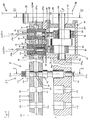
- Internal combustion engine 10 shows an elongated, straight rail 12, the parallel to a cylinder head housing belonging to the internal combustion engine 10 14 is arranged, and a high pressure pump 16 thereof Drive in a known, later described manner from Internal combustion engine 10 takes place.
- the rail has a pressure chamber 20 and along its longitudinal axis 18 perpendicular to it, piercing the rail 12 in the area of the pressure chamber 20, Openings 22 for receiving injectors 24.
- the Openings 22 are parallel to one another with their opening axes 26 arranged and lie in one plane. In their extension, the Opening axes 26 also the axes of injector openings 28 of the Cylinder head housing 14.
- the injectors 24, when they pass through the openings 22 of the rail 12 into the injector openings 28 of the cylinder head housing 14 are used with their injector axes 26a parallel to one another and in one plane.
- the injectors 24 essentially have are rotationally symmetrical, at one end injection nozzles 30 on.
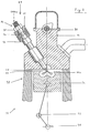
- the injectors 24 are shaped such that the injection nozzles 30 after installation in a combustion chamber 32 shown in FIG. 2 of the internal combustion engine 10 protrude.
- One of the injector 30 opposite injector head 34 protrudes beyond the rail 12.
- the injectors 24 in the section after the Insert the injectors 24 at the level of the pressure chamber 20 of the rail 12 lies, a circumferential groove 36 through which it is ensured that the Injectors 24 flow around the pressure medium located in the pressure chamber 20 can be.
- This section of the injectors 24 are also located Inlet openings 38 through which the pressure medium enters the injectors 24 can flow in.
- a fastener 40 for example a screw connection
- the injectors 24 are fixed in the rail 12.
- the rail 12 On the side of the high pressure pump 16, the rail 12 has two receiving openings 44 for receiving plunger cylinders 46 and one Channel 20a on.
- the channel 20a goes in the dashed line 48 in the Pressure chamber 20 of the rail 12 and connects the receiving openings 44 with the pressure chamber 20 of the rail 12. So that the pressure medium used Plunger cylinders 46 can flow around the channel 20a circumferential grooves embedded in the plunger cylinder 46, which at used plunger cylinders 46 an annular channel 50 (indicated by dashed lines) form around the plunger cylinders 46.
- the plunger cylinders 46 are over a press fit in the rail 12 fixes what the same effect as that Enclose the plunger cylinder with a pressure body, as in the older one CH Patent Application No. 1997 1275/97.
- the receiving openings 44 made in the rail 12 for the plunger cylinders 46 have axes 52 lying parallel to one another, which in one Plane with and parallel to the opening axes 26 of the openings 22 in the Rail 12 or the injector axes 26a of the injectors 24 are arranged. This leads to the fact that the plunger cylinders 46 after their insertion in the receiving openings 44 with their plunger axes 52a parallel and in lie on a plane to the opening axes 26 and the injector axes 26a.
- Each plunger cylinder 46 defines together with a plunger 54 a delivery space 56.
- This delivery space 56 is in the plunger cylinder 46 let inlet channel 58 and a feed line 58a with a reservoir for the pressure medium, not shown.
- the pressure medium is fed in through a pressure-controlled inlet valve 60 regulated.
- the high pressure pump 16 has a pump housing 66, to which below another includes a housing element 68 with a side wall 68a in which Housing openings 70 are excluded.
- the plunger cylinders 46 protrude now with the side in which the plungers 54 in the plunger cylinders 46 are guided into these housing openings 70 of the side wall 68a of the housing element 68 in.
- the housing openings 70 are so designed that between the plunger cylinders 46 and the Housing element 68 remains a small gap 72, so that the plunger cylinders 46 can be inserted into the housing element 68 with some play.
- the housing element 68 is above the side wall 68a via the columns 72 open to the outside. Through the rail 12, which on the side wall 68a of the Housing element 68 is arranged close to the housing element 68 as if closed by a lid.
- Housing element 68 is formed on the inside as a bearing Recess 76 incorporated in which the drive shaft 78 with the Power transmission opposite end region 78a is mounted.
- the wall 74 at the dashed dividing line 74a goes into the integrally molded cylinder head housing 14 on.
- the wall 74 of the housing element 68 closes a side plate 80 which also belongs to the pump housing 66, a further opening of the housing element 68.
- a bearing opening 82 of this side plate 80 is the Drive shaft 78 on its side facing the power transmission stored. In the case of repairs, access is also via this side plate 80 allows the inside of the pump housing 66.
- the plunger cylinders 46 with the plungers 54 and the drive shaft 78 the high pressure pump 16 are arranged at right angles to each other.
- For the Stroke movement of - by means of compression springs 83 in the direction against Drive shaft 78 pushed - plunger 54 in the plunger cylinders 46 of the high pressure pump 16 are on the drive shaft 78 of the high pressure pump 16 eccentric 84 attached.
- Between the eccentrics 84 and the plunger 54 are rolling rings 86 in a known manner attached, which can rotate freely on the eccentric 84.
- the high-pressure pump 16 is driven in the embodiment shown here the drive shaft 78 via a spur gear mechanism indicated in FIGS. 1 and 3 88 with a camshaft which is also only shown in a hint 90 of the internal combustion engine 10 coupled.
- FIG. 2 shows the common rail injection system 8 according to the invention Fig. 1 along the section axis II-II.
- the injector 24 is over the fastener 40 and the attachment 42 fixed in the rail 12 and in the Injector opening 28 of the cylinder head housing 14 inserted.
- the one in 3 only schematically indicated internal combustion engine 10 with a Engine housing 92 is only partially shown as a reciprocating piston engine formed in the piston 94, the combustion chamber 32 incorporated is.
- the injection nozzle 30 of the injector 24 projects into this combustion chamber 32 in.
- the piston 94 is via a crank mechanism 96 connected to a crankshaft 98, which is only hinted at is.
- FIG. 3 is the injection system 8 from FIG. 1 along the section III-III shown.
- the dashed circular lines 100 and the arrows 102 indicate the power transmission from the camshaft 90 via the spur gear 88 to the drive shaft 78 of the high pressure pump 16.
- Right angled to the drive shaft 78 is the plunger cylinder enclosed by the rail 12 46 arranged and with the supply line 58a for the inflow of the pressure medium Mistake.
- the internal combustion engine 10 is with its motor housing 92, piston 94, crank gear 96 and crankshaft 98 also only hinted at here.
- the injection system 8 it is advantageous for the functioning of the injection system 8 necessary that the rotational movement of the drive shaft 78 and that of the Camshaft 90 of the internal combustion engine 10 is operated in angular synchronism become.
- the drive shaft 78 is then preferably driven, for example, via the spur gear 88, in a known manner from the camshaft 90, as indicated in FIGS. 1 and 3. Due to the rotational movement of the drive shaft 78, mediated by the Eccentric 84, the plungers 54 perform stroke movements.
- the compression stroke of the plunger 54 closes the inlet valve 60 and the outlet valve 64 opens under pressure control and gives the passage 62 free.
- the pressure medium can thus through the passage 62 from the Delivery chamber 56 into the ring channel 50 and further into the channel 20a of the rail 12 stream. From there it flows further into the pressure space 20 of the rail 12 and through the inlet openings 38 into the interior of the injectors 24.
- the indicated injection process 104 becomes an electrical signal triggered and the print medium at high speed and high Pressure finely distributed into the combustion chamber 32.
- a is used instead of the rail 12 Housing cover 106 close to the side wall 68a of the Housing elements 68 arranged and that over the columns 72 between the used plunger cylinders 46 and the housing element 68 open Housing element 68 closed in this way.
- the Housing cover 106 analogous to the rail 12 receiving openings 44 for the Receiving the plunger cylinder 46 and have a channel 20a.
- the housing cover 106 which have a Press fit plunger 46 used so that everyone Delivery chamber 56 through the passage 62 and the through the annular groove Plunger cylinder 46 shaped ring channel 50 with the channel 20a of the Housing cover 106 is connected. That containing the plunger cylinders 46 Component, which in FIG.
- the housing cover 106 to which the Rail 12 is integrally formed on the dashed line 48.
- the rail 12 in a different way, e.g. about a high pressure hose with the channel 20a of the housing cover 106 would be connected.
- the housing element 68 itself can also have receiving openings 44 for the accommodation of the plunger cylinders 46 and a channel 20a may be provided, such that the plunger cylinders 46 directly into the housing element 68 a press fit can be used. They are here too Plunger cylinder 46 configured so that the delivery chamber 56 over the Passage 62 and the ring channel 50 is connected to the channel 20a.
- rail 12 only has openings 22 for receiving the Injectors 24 but not the receiving openings 44 for the plunger cylinders 46 on.
- the pressure chamber 20 of the rail 12 can then either over High pressure hoses with the channel 20a of the housing element 68 be connected or in that the rail 12 directly to the Housing element 68 is integrally formed.
- the housing element 68 Integrated part of the cylinder head housing 14 and thus the Motor housing 92.
- Other embodiments in which other parts of the pump housing 66 is an integral part of the motor housing 92 preferably the cylinder head housing 14 of the internal combustion engine 10 are, but are also conceivable.
- the rail 12 on the one hand the cylinder head housing 14 and on the other hand to the housing cover 106 or the housing element 68 can be integrally formed so that these elements over the rail 12 in the engine housing 92 or the cylinder head housing 14 to get integrated.
- Housing cover 106 or side plate 80 can also be in the engine housing 92 or the cylinder head housing 14 may be integrated or combinations of these parts.
Landscapes
- Engineering & Computer Science (AREA)
- Chemical & Material Sciences (AREA)
- Combustion & Propulsion (AREA)
- Mechanical Engineering (AREA)
- General Engineering & Computer Science (AREA)
- Fuel-Injection Apparatus (AREA)
- Cylinder Crankcases Of Internal Combustion Engines (AREA)
Applications Claiming Priority (3)
| Application Number | Priority Date | Filing Date | Title |
|---|---|---|---|
| CH2557/97 | 1997-11-05 | ||
| CH255797 | 1997-11-05 | ||
| CH255797 | 1997-11-05 |
Publications (2)
| Publication Number | Publication Date |
|---|---|
| EP0915252A2 true EP0915252A2 (fr) | 1999-05-12 |
| EP0915252A3 EP0915252A3 (fr) | 2000-03-15 |
Family
ID=4236484
Family Applications (1)
| Application Number | Title | Priority Date | Filing Date |
|---|---|---|---|
| EP98117887A Withdrawn EP0915252A3 (fr) | 1997-11-05 | 1998-09-21 | Système d'injection par alimentation commune des injecteurs |
Country Status (3)
| Country | Link |
|---|---|
| EP (1) | EP0915252A3 (fr) |
| JP (1) | JPH11200986A (fr) |
| CA (1) | CA2251148A1 (fr) |
Cited By (11)
| Publication number | Priority date | Publication date | Assignee | Title |
|---|---|---|---|---|
| WO2001023749A1 (fr) * | 1999-09-29 | 2001-04-05 | Robert Bosch Gmbh | Accumulateur de carburant haute pression |
| EP1101931A2 (fr) | 1999-11-19 | 2001-05-23 | CRT Common Rail Technologies AG | Système d'injection à haute pression avec common rail |
| EP0990792A3 (fr) * | 1998-09-30 | 2003-05-21 | CRT Common Rail Technologies AG | Système d'injection de carburant de type Common-Rail |
| WO2004079182A1 (fr) * | 2003-03-04 | 2004-09-16 | Siemens Aktiengesellschaft | Accumulateur de carburant haute pression |
| EP1298316A3 (fr) * | 2001-09-26 | 2005-02-02 | DEUTZ Aktiengesellschaft | Système d'injection de carburant |
| EP2088310A1 (fr) * | 2008-02-08 | 2009-08-12 | DEUTZ Aktiengesellschaft | Moteur à combustion interne doté d'un système d'injection Common-Rail |
| WO2011088958A1 (fr) * | 2010-01-22 | 2011-07-28 | Robert Bosch Gmbh | Pompe à haute pression |
| DE102010051883A1 (de) * | 2010-11-22 | 2012-05-24 | Benteler Automobiltechnik Gmbh | Kraftstoffverteiler |
| DE102015205170A1 (de) | 2015-03-23 | 2016-09-29 | Bayerische Motoren Werke Aktiengesellschaft | Kraftstoffeinspritzvorrichtung |
| DE102015205169A1 (de) | 2015-03-23 | 2016-09-29 | Bayerische Motoren Werke Aktiengesellschaft | Kraftstoffeinspritzvorrichtung |
| DE102015209646A1 (de) | 2015-05-27 | 2016-12-01 | Bayerische Motoren Werke Aktiengesellschaft | Kraftstoffeinspritzvorrichtung |
Families Citing this family (5)
| Publication number | Priority date | Publication date | Assignee | Title |
|---|---|---|---|---|
| US9200563B2 (en) | 2013-03-12 | 2015-12-01 | Pratt & Whitney Canada Corp. | Internal combustion engine with common rail pilot and main injection |
| US9879591B2 (en) | 2015-02-20 | 2018-01-30 | Pratt & Whitney Canada Corp. | Engine intake assembly with selector valve |
| US9896998B2 (en) | 2015-02-20 | 2018-02-20 | Pratt & Whitney Canada Corp. | Compound engine assembly with modulated flow |
| US9797297B2 (en) | 2015-02-20 | 2017-10-24 | Pratt & Whitney Canada Corp. | Compound engine assembly with common inlet |
| US9932892B2 (en) | 2015-02-20 | 2018-04-03 | Pratt & Whitney Canada Corp. | Compound engine assembly with coaxial compressor and offset turbine section |
Citations (3)
| Publication number | Priority date | Publication date | Assignee | Title |
|---|---|---|---|---|
| CH127597A (de) | 1927-05-25 | 1928-09-01 | Sulzer Ag | Stehende Kolbenmaschine, insbesondere Verbrennungskraftmaschine. |
| US5603303A (en) | 1994-04-28 | 1997-02-18 | Nippondenso Co., Ltd. | High pressure fuel supply pump |
| JPH0960562A (ja) | 1995-08-24 | 1997-03-04 | Nissan Motor Co Ltd | 直噴式内燃機関 |
Family Cites Families (4)
| Publication number | Priority date | Publication date | Assignee | Title |
|---|---|---|---|---|
| FR2701295B1 (fr) * | 1993-02-05 | 1995-04-28 | Sindra Sa | Rampe d'injection de carburant et l'un de ses procédés de fabrication. |
| US5538403A (en) * | 1994-05-06 | 1996-07-23 | Cummins Engine Company, Inc. | High pressure pump for fuel injection systems |
| JP2689226B2 (ja) * | 1994-12-02 | 1997-12-10 | 株式会社ゼクセル | 高圧燃料噴射装置用燃料ポンプ |
| JPH0988761A (ja) * | 1995-09-26 | 1997-03-31 | Isuzu Motors Ltd | 内燃機関の燃料噴射装置 |
-
1998
- 1998-09-21 EP EP98117887A patent/EP0915252A3/fr not_active Withdrawn
- 1998-10-14 JP JP10291931A patent/JPH11200986A/ja active Pending
- 1998-10-19 CA CA002251148A patent/CA2251148A1/fr not_active Abandoned
Patent Citations (3)
| Publication number | Priority date | Publication date | Assignee | Title |
|---|---|---|---|---|
| CH127597A (de) | 1927-05-25 | 1928-09-01 | Sulzer Ag | Stehende Kolbenmaschine, insbesondere Verbrennungskraftmaschine. |
| US5603303A (en) | 1994-04-28 | 1997-02-18 | Nippondenso Co., Ltd. | High pressure fuel supply pump |
| JPH0960562A (ja) | 1995-08-24 | 1997-03-04 | Nissan Motor Co Ltd | 直噴式内燃機関 |
Cited By (16)
| Publication number | Priority date | Publication date | Assignee | Title |
|---|---|---|---|---|
| EP0990792A3 (fr) * | 1998-09-30 | 2003-05-21 | CRT Common Rail Technologies AG | Système d'injection de carburant de type Common-Rail |
| WO2001023749A1 (fr) * | 1999-09-29 | 2001-04-05 | Robert Bosch Gmbh | Accumulateur de carburant haute pression |
| EP1101931A2 (fr) | 1999-11-19 | 2001-05-23 | CRT Common Rail Technologies AG | Système d'injection à haute pression avec common rail |
| US6330876B1 (en) | 1999-11-19 | 2001-12-18 | Crt Common Rail Technologies Ag | High-pressure injection system with common rail |
| US6745753B2 (en) | 1999-11-19 | 2004-06-08 | Crt Common Rail Technologies Ag | High-pressure injection system |
| EP1298316A3 (fr) * | 2001-09-26 | 2005-02-02 | DEUTZ Aktiengesellschaft | Système d'injection de carburant |
| US7182069B2 (en) | 2003-03-04 | 2007-02-27 | Siemens Aktiengesellschaft | High pressure fuel accumulator |
| US7040289B2 (en) | 2003-03-04 | 2006-05-09 | Siemens Aktiengesellschaft | High pressure fuel accumulator |
| WO2004079182A1 (fr) * | 2003-03-04 | 2004-09-16 | Siemens Aktiengesellschaft | Accumulateur de carburant haute pression |
| EP2088310A1 (fr) * | 2008-02-08 | 2009-08-12 | DEUTZ Aktiengesellschaft | Moteur à combustion interne doté d'un système d'injection Common-Rail |
| WO2011088958A1 (fr) * | 2010-01-22 | 2011-07-28 | Robert Bosch Gmbh | Pompe à haute pression |
| DE102010051883A1 (de) * | 2010-11-22 | 2012-05-24 | Benteler Automobiltechnik Gmbh | Kraftstoffverteiler |
| DE102010051883B4 (de) * | 2010-11-22 | 2016-06-02 | Benteler Automobiltechnik Gmbh | Kraftstoffverteiler |
| DE102015205170A1 (de) | 2015-03-23 | 2016-09-29 | Bayerische Motoren Werke Aktiengesellschaft | Kraftstoffeinspritzvorrichtung |
| DE102015205169A1 (de) | 2015-03-23 | 2016-09-29 | Bayerische Motoren Werke Aktiengesellschaft | Kraftstoffeinspritzvorrichtung |
| DE102015209646A1 (de) | 2015-05-27 | 2016-12-01 | Bayerische Motoren Werke Aktiengesellschaft | Kraftstoffeinspritzvorrichtung |
Also Published As
| Publication number | Publication date |
|---|---|
| JPH11200986A (ja) | 1999-07-27 |
| EP0915252A3 (fr) | 2000-03-15 |
| CA2251148A1 (fr) | 1999-05-05 |
Similar Documents
| Publication | Publication Date | Title |
|---|---|---|
| EP0391366B1 (fr) | Appareil d'injection de combustible | |
| EP1931875B1 (fr) | Pompe haute pression utilisee en particulier pour un dispositif d'injection du carburant d'un moteur a combustion interne, | |
| EP0915252A2 (fr) | Système d'injection par alimentation commune des injecteurs | |
| DE3732259C2 (de) | Verfahren und Vorrichtung zum Einspritzen von Kraftstoff in einen Verbrennungsmotor | |
| EP1714030B1 (fr) | Pompe haute pression, notamment pour systeme d'injection de carburant de moteur a combustion interne | |
| DE4237469A1 (de) | Kraftstoffeinspritzeinrichtung, insbesondere Pumpedüse für Brennkraftmaschinen | |
| EP1561028B1 (fr) | Pompe haute pression d'alimentation en carburant comprenant un clapet a bille dans l'admission basse pression | |
| DE102018214212A1 (de) | Hochdruck-Kraftstoffpumpe | |
| WO2013092968A2 (fr) | Pompe, en particulier pompe carburant haute pression pour un dispositif d'injection de carburant | |
| DE10129449A1 (de) | Kraftstoffhochdruckpumpe für Brennkraftmaschine mit verbessertem Teillastverhalten | |
| EP1576287A1 (fr) | Pompe haute pression pour un dispositif d'injection de carburant d'un moteur a combustion interne | |
| EP2561213A1 (fr) | Pompe haute pression | |
| EP0990792A2 (fr) | Système d'injection de carburant de type Common-Rail | |
| EP1361357A2 (fr) | Pompe à carburant notamment pour un moteur à combustion interne et à injection directe | |
| DE4437927A1 (de) | Injektor mit Magnetventilsteuerung zur Kraftstoffeinspritzung in den Brennraum einer Dieselbrennkraftmaschine | |
| EP1537334B1 (fr) | Pompe, notamment pour un systeme d'injection de carburant destine a un moteur a combustion interne | |
| EP0881380A1 (fr) | Pompe d'alimentation haute-pression | |
| DE102004019626B4 (de) | Kraftstoffeinspritzpumpe und Dreh-/Linearbewegungsumwandlungsmechanismus mit Sicherungseinrichtung | |
| EP1211419A2 (fr) | Dispositif pour refouler du carburant | |
| DE19941709A1 (de) | Gebautes Steuerventil für einen Injektor eines Kraftstoffeinspritzsystems für Brennkraftmaschinen | |
| EP0688397A1 (fr) | Moteur a combustion interne a injection de carburant, notamment moteur diesel monocylindre | |
| DE102008042649A1 (de) | Steckpumpe | |
| DE19721241C1 (de) | Pumpedüse | |
| DE10355028A1 (de) | Hochdruckpumpe, insbesondere für eine Kraftstoffeinspritzeinrichtung einer Brennkraftmaschine | |
| EP0027792A1 (fr) | Pompe d'injection pour moteurs à combustion interne à injection du combustible, en particulier pour moteurs diesel |
Legal Events
| Date | Code | Title | Description |
|---|---|---|---|
| PUAI | Public reference made under article 153(3) epc to a published international application that has entered the european phase |
Free format text: ORIGINAL CODE: 0009012 |
|
| AK | Designated contracting states |
Kind code of ref document: A2 Designated state(s): AT BE CH CY DE DK ES FI FR GB GR IE IT LI LU MC NL PT SE |
|
| AX | Request for extension of the european patent |
Free format text: AL;LT;LV;MK;RO;SI |
|
| PUAL | Search report despatched |
Free format text: ORIGINAL CODE: 0009013 |
|
| AK | Designated contracting states |
Kind code of ref document: A3 Designated state(s): AT BE CH CY DE DK ES FI FR GB GR IE IT LI LU MC NL PT SE |
|
| AX | Request for extension of the european patent |
Free format text: AL;LT;LV;MK;RO;SI |
|
| AKX | Designation fees paid | ||
| STAA | Information on the status of an ep patent application or granted ep patent |
Free format text: STATUS: THE APPLICATION IS DEEMED TO BE WITHDRAWN |
|
| 18D | Application deemed to be withdrawn |
Effective date: 20000916 |
|
| REG | Reference to a national code |
Ref country code: DE Ref legal event code: 8566 |