EP0915436A1 - Weiche für Dokumente - Google Patents
Weiche für Dokumente Download PDFInfo
- Publication number
- EP0915436A1 EP0915436A1 EP98308822A EP98308822A EP0915436A1 EP 0915436 A1 EP0915436 A1 EP 0915436A1 EP 98308822 A EP98308822 A EP 98308822A EP 98308822 A EP98308822 A EP 98308822A EP 0915436 A1 EP0915436 A1 EP 0915436A1
- Authority
- EP
- European Patent Office
- Prior art keywords
- feed path
- notes
- deflecting means
- routing mechanism
- document routing
- Prior art date
- Legal status (The legal status is an assumption and is not a legal conclusion. Google has not performed a legal analysis and makes no representation as to the accuracy of the status listed.)
- Granted
Links
- 230000007246 mechanism Effects 0.000 title claims abstract description 56
- 230000004913 activation Effects 0.000 abstract description 2
- 230000015654 memory Effects 0.000 description 4
- 230000007723 transport mechanism Effects 0.000 description 4
- 238000010276 construction Methods 0.000 description 2
- 238000012790 confirmation Methods 0.000 description 1
- 230000001419 dependent effect Effects 0.000 description 1
- 238000000151 deposition Methods 0.000 description 1
- 238000010586 diagram Methods 0.000 description 1
- 238000003780 insertion Methods 0.000 description 1
- 230000037431 insertion Effects 0.000 description 1
- 238000000034 method Methods 0.000 description 1
- 230000000284 resting effect Effects 0.000 description 1
- 230000000717 retained effect Effects 0.000 description 1
- 238000004804 winding Methods 0.000 description 1
Images


Classifications
-
- B—PERFORMING OPERATIONS; TRANSPORTING
- B65—CONVEYING; PACKING; STORING; HANDLING THIN OR FILAMENTARY MATERIAL
- B65H—HANDLING THIN OR FILAMENTARY MATERIAL, e.g. SHEETS, WEBS, CABLES
- B65H29/00—Delivering or advancing articles from machines; Advancing articles to or into piles
- B65H29/006—Winding articles into rolls
-
- B—PERFORMING OPERATIONS; TRANSPORTING
- B65—CONVEYING; PACKING; STORING; HANDLING THIN OR FILAMENTARY MATERIAL
- B65H—HANDLING THIN OR FILAMENTARY MATERIAL, e.g. SHEETS, WEBS, CABLES
- B65H29/00—Delivering or advancing articles from machines; Advancing articles to or into piles
- B65H29/58—Article switches or diverters
-
- G—PHYSICS
- G07—CHECKING-DEVICES
- G07D—HANDLING OF COINS OR VALUABLE PAPERS, e.g. TESTING, SORTING BY DENOMINATIONS, COUNTING, DISPENSING, CHANGING OR DEPOSITING
- G07D11/00—Devices accepting coins; Devices accepting, dispensing, sorting or counting valuable papers
- G07D11/10—Mechanical details
- G07D11/16—Handling of valuable papers
- G07D11/18—Diverting into different paths or containers
-
- B—PERFORMING OPERATIONS; TRANSPORTING
- B65—CONVEYING; PACKING; STORING; HANDLING THIN OR FILAMENTARY MATERIAL
- B65H—HANDLING THIN OR FILAMENTARY MATERIAL, e.g. SHEETS, WEBS, CABLES
- B65H2220/00—Function indicators
- B65H2220/09—Function indicators indicating that several of an entity are present
-
- B—PERFORMING OPERATIONS; TRANSPORTING
- B65—CONVEYING; PACKING; STORING; HANDLING THIN OR FILAMENTARY MATERIAL
- B65H—HANDLING THIN OR FILAMENTARY MATERIAL, e.g. SHEETS, WEBS, CABLES
- B65H2301/00—Handling processes for sheets or webs
- B65H2301/40—Type of handling process
- B65H2301/41—Winding, unwinding
- B65H2301/419—Winding, unwinding from or to storage, i.e. the storage integrating winding or unwinding means
- B65H2301/4191—Winding, unwinding from or to storage, i.e. the storage integrating winding or unwinding means for handling articles of limited length, e.g. AO format, arranged at intervals from each other
- B65H2301/41912—Winding, unwinding from or to storage, i.e. the storage integrating winding or unwinding means for handling articles of limited length, e.g. AO format, arranged at intervals from each other between two belt like members
-
- B—PERFORMING OPERATIONS; TRANSPORTING
- B65—CONVEYING; PACKING; STORING; HANDLING THIN OR FILAMENTARY MATERIAL
- B65H—HANDLING THIN OR FILAMENTARY MATERIAL, e.g. SHEETS, WEBS, CABLES
- B65H2403/00—Power transmission; Driving means
- B65H2403/40—Toothed gearings
- B65H2403/42—Spur gearing
-
- B—PERFORMING OPERATIONS; TRANSPORTING
- B65—CONVEYING; PACKING; STORING; HANDLING THIN OR FILAMENTARY MATERIAL
- B65H—HANDLING THIN OR FILAMENTARY MATERIAL, e.g. SHEETS, WEBS, CABLES
- B65H2404/00—Parts for transporting or guiding the handled material
- B65H2404/60—Other elements in face contact with handled material
- B65H2404/63—Oscillating, pivoting around an axis parallel to face of material, e.g. diverting means
- B65H2404/632—Wedge member
-
- B—PERFORMING OPERATIONS; TRANSPORTING
- B65—CONVEYING; PACKING; STORING; HANDLING THIN OR FILAMENTARY MATERIAL
- B65H—HANDLING THIN OR FILAMENTARY MATERIAL, e.g. SHEETS, WEBS, CABLES
- B65H2701/00—Handled material; Storage means
- B65H2701/10—Handled articles or webs
- B65H2701/19—Specific article or web
- B65H2701/1912—Banknotes, bills and cheques or the like
Definitions
- the present invention relates to document routing mechanism and in particular, to a document routing mechanism associated with a storage device for currency notes in an automated teller machine (ATM).
- ATM automated teller machine
- Currency notes are generally stored in one or more currency cassettes within the cash dispenser module of an ATM. During a cash withdrawal transaction, the requisite notes must be picked from the appropriate cassette or cassettes by a vacuum or friction picking mechanism and fed along a main transport path to a stacking mechanism, prior to being delivered to a customer through a slot in the front panel of the ATM. In order to increase the speed and efficiency at which currency notes are dispensed to a customer, currency notes may be picked from one or more of the currency cassettes prior to receipt of a customer cash withdrawal request and are transported to one or more auxiliary storage devices (escrows) for temporary storage.
- auxiliary storage devices escrows
- the auxiliary storage devices are located along the transport path closer to the stacking mechanism than the currency cassettes and are arranged to dispense currency notes at a faster rate than dispensing from the main currency cassettes. In subsequent cash withdrawal transactions, if at least some of the notes required for the transaction are available in the auxiliary storage devices, these notes are dispensed therefrom in preference to, or in addition to the notes from the currency cassettes.
- a document routing mechanism for an ATM currency note storage device is described in US 4871125.
- the routing mechanism comprises a pair of curved baffles and a gating mechanism having a core member which can be moved between a first position to define a transport path into the escrow and a second position to define a transport path out of the escrow.
- the core member is moved by means of an electromagnet and a lever linkage which is connected to the core member.
- this known mechanism is complex and bulky and has a limited operating speed.
- a document routing mechanism for selectively directing documents travelling along a first feed path to either a second feed path or to a continuation of the first feed path, and for selectively directing documents returning on the second feed path to the continuation of the first feed path, comprising deflecting means for movement within the first feed path and the second feed path and in that the deflecting means comprises a first deflecting means moveable within the first feed path and, a second deflecting means moveable within the second feed path wherein the first deflecting means is moveable relative to the second deflecting means.
- the relative movement between the first and second deflecting means allows for a particularly compact and reliable configuration for the document routing mechanism of the present invention.
- the first and second deflector means are driven for movement by a common drive means.
- This arrangement allows for simple operation of the routing mechanism so as to achieve the required operating speeds with the required degree of reliability.
- the first deflecting means is preferably operatively connected to the second defecting means in such a way that movement of one of the deflecting means cause movement of the other deflecting means.
- Each of the first and second deflector means preferably comprises a pivotally mounted document deflection member and may be arranged for relative pivotal movement.
- the document routing mechanism of the present invention may be used in connection with a storage device for currency notes in the cash dispenser module of an automated teller machine (ATM) in which the second path represents a feed path to, and delivery path from, the storage device.
- ATM automated teller machine
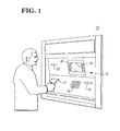
- a user panel 12 including a card reader slot 14 for insertion of a user's identification card, a key pad 16, a cash dispenser slot 18 through which currency notes are delivered to a user, a display screen 20, a receipt printer slot 22 through which a receipt for a transaction is delivered to the user at the end of a transaction and additional keytips at the sides of the screen 20 to facilitate selection of options or confirmation of information displayed on the screen 20.
- the card reader, cash dispenser and receipt printer modules associated with the respective slots 14, 18 and 22 in the user panel 12 of the ATM 10, are designated by the same reference numerals in Fig. 2.
- a user inserts his card into the card reader slot 14 and data encoded on the card is read. Instructions are then displayed on the screen 20. The user is requested to enter a personal identification number (PIN) on the key pad 16 which is verified, usually at a central location remote from the ATM 10. If the PIN is determined to be correct against information read from the inserted card, a menu of the various facilities available to the user is then displayed on the screen 20. If a cash withdrawal facility is selected, the user is requested to enter the sum required on the key pad 16 or by means of the additional keys 24 provided at the side of the screen 20.
- PIN personal identification number
- the ATM 10 further comprises a controller unit 30 which communicates with components of the user panel 12 and with various other operating mechanisms of the ATM 10.
- the controller unit 30 includes a processor unit 32, and a memory unit 34 connected via a bus line 36 to the processor unit 32.
- the processor unit 32 receives input signals from the card reader 14, the key pad 16 and the additional keytips 24, and provides output signals to various mechanisms of the cash dispenser 18, to the display 20 and to the receipt printer 22. It should be understood that the processor unit 32 controls the amount of cash dispensed by the cash dispenser 18, the information displayed on the display 20 and the information printed by the receipt printer 22.
- the various mechanisms within the cash dispenser 18 controlled by the processor unit 32 include a multiple note detector 62 for detecting the presence of multiple superposed currency notes, vacuum operated picker devices 44 for picking notes from currency cassettes 40, a transport mechanism 45 for transporting notes picked from one or more of the cassettes 40 or dispensed from an auxiliary storage device 52, a document routing mechanism 50 for selectively directing picked notes towards an auxiliary storage device 52 for storage and for directing notes dispensed from the auxiliary storage device 52 toward a stacking wheel 70 and a drive motor 53 of an auxiliary storage device 52.
- the processor unit 32 may include a microcomputer, and the memory unit 34 may be a non-volatile RAM. Suitable computers and memories are readily available in the marketplace. Their structure and operation are well known and therefore will not be described.
- Stacks of currency notes 38 are held in the cassettes 40, the cassettes being slidably mounted in compartments 42 and each holding notes of different denominations.
- the picker devices 44 serve to extract notes from each cassette 40.
- the transport mechanism 45 is associated with a three feed paths 46, 46a and 48 linked by a document routing mechanism 50 and serves to transfer notes from one location to another within the ATM 10.
- the document routing mechanism 50 is controlled by the controller unit 30 to pivot between different positions according to the selected path of transport of notes within the ATM 10.
- the transport mechanism 45 transfers notes picked from the cassettes 40 along a first unidirectional main feed path 46, either to a continuation portion of the main feed path 46, i.e. path 46a, for delivery to a customer, or to a second feed path 48 for delivery to an auxiliary storage device 52.
- Documents stored in the auxiliary storage device 52 can be returned to the continuation portion 46a of the main feed path 46 by means of the document routing mechanism 50 as will be described later.
- a diverter 60 is provided along the main feed path 46 to direct any mispicked notes which are detected by the multiple note detector 62 into a first reject bin 64.
- a stacking wheel 70 and stripper plate assembly 72 are provided at the end of the continuation portion 46a of the main feed path 46, for stacking notes prior to being delivered to a customer through a shutter 89 associated with the cash dispenser slot 18 via a series of co-operating belts 80, 82, 84 and 86.
- the stacking wheel 70 comprises a plurality of stacking plates 74, spaced apart in parallel relationship along the shaft 75 of the stacking wheel 70, each stacking plate 74 incorporating a series of curved tines 77 which pass between fingers 78 of the stripper plate assembly 72 rockably mounted on a shaft 79.
- a further reject bin 88 is provided for notes which are retracted from the cash dispenser slot 18, in the event a customer omits to remove them therefrom at the end of a cash withdrawal transaction.
- the document routing mechanism 50 comprises a gating mechanism 54 at the intersection between the main feed path 46 and the second feed path 48.
- the gating mechanism 54 includes an isolated support 55 on which first and second flipper arms 56a and 56b are pivotally mounted.
- a gearing mechanism 58a and 58b is provided on the mutually adjacent ends of each of the flipper arms 56a and 56b, the gear wheels 58a and 58b of which are arranged to mesh such that pivotal movement of one of the flipper arms 56a or 56b will cause pivotal movement of the other flipper arm 56a or 56b.
- a solenoid mechanism (not shown) is provided to cause pivotal movement of the flipper arms 56a and 56b.
- the auxiliary storage device 52 is shown in more detail in Fig. 5, but it should be appreciated that the device may take a variety of other physical forms such as, for example, a storage stack.
- the auxiliary storage device 52 is operated on a "last in first out” (LIFO) basis and is preferably chosen to have less inertia than the currency cassettes 40, so that it can dispense notes at a faster rate than dispensing from the currency cassettes 40.
- the auxiliary storage device 52 comprises a main storage drum 90, first and second tape feeder drum means 92 and 94 which are rotatably mounted within a housing 96.
- a first tape 97 is secured at one end to the main storage drum 90 and at its opposite end to the first feeder drum means 92, while a second tape 98 is secured at one end to main storage drum 90 and at its opposite end to the second feeder drum means 94, the tapes 97 and 98 being wound about the main drum 90 and their respective feeder drums means 92 and 94.
- each tape 97 and 98 could comprise two or more separate tapes spaced apart along the axis of the main storage drum, while each tape feeder drum means 92 and 94 could comprise two or more separate drums spaced apart along a common axis.
- notes are directed by the document routing mechanism 50 from the main feed path 46 to the second feed path 48 and are fed into the auxiliary storage device 52 where they pass between the tapes 97 and 98.
- the main drum 90 is driven to rotate in a clockwise direction (with reference to Fig. 4) winding the tapes 97 and 98 and notes held therebetween, onto the main drum 90.
- the notes are securely held on the main drum 90 between wrappings of the tapes 97 and 98.
- the feeder drum means 92 and 94 are driven to rotate in a clockwise direction, causing the tapes 97 and 98 to wind off the main drum 90 and the individual notes to be unloaded and fed out of the auxiliary storage device 52 onto the second feed path 48.
- notes are periodically transferred from the currency cassettes 40 to the auxiliary storage device 52.
- the notes to be transferred are picked from the cassettes 40 by the picker devices 44 and are fed by the transport mechanism 45 along the main feed path 46, the direction of feed of the notes being perpendicular to their long dimensions. If the presence of multiple superposed notes is detected by the detector 62, the divertor 60 is controlled to pivot to a position in which passage of the notes along the main feed path 46 is blocked and the multiple note is directed via rolls 59 into a reject bin 64.
- An energisation signal is transmitted to the solenoid of the gating mechanism 54 by the controller unit 32.
- Energisation of the solenoid causes pivotal movement of the flipper arm 56a in an anticlockwise direction (with reference to Figures 4A and 4B) into the first feed path 46 so as to block the passage of documents to continuation portion 46a thereof.
- Pivotal movement of the flipper arm 56a causes pivotal movement of the other flipper arm 56b in a clockwise direction (with reference to Figures 4A and 4B) so as to define a path from the first feed path 46 to the second feed path 48 as is shown in Figure 4B.
- the flipper arms 56a and 56 b are retained in the relative positions shown in Figure 4B under the action of resilient return means (not shown) associated with the solenoid (not shown). In this position, the picked notes are therefore directed from the main feed path 46 to the second feed path 48 and are then fed to the auxiliary storage device 52 for storage.
- the solenoid is de-energised causing pivotal movement of the flipper arm 54a in a clockwise direction (with reference to Figures 4A and 4B), out of the first feed path 46 and the continuation portion 46a thereof, and pivotal movement of the flipper arm 54b in an anticlockwise direction (with reference to Figures 4A and 4B) into the second feed path 48 to the rest position shown in Figure 4A.
- the denomination of the notes and the order in which they are transferred to the auxiliary storage device 52 is stored in the memory 34 of the ATM controller unit 30.
- Notes stored in the auxiliary storage device 52 may be dispensed during subsequent customer transactions in preference to, or in addition to, notes from the currency cassettes 40. If at least some of the required notes are available in the auxiliary storage device 52, they are dispensed therefrom on a "last in first out” basis (LIFO) and fed along the second bi-directional feed path 48 towards the gating mechanism 54.
- the flipper arms 54a and 54b remain in the rest position shown in Figure 4A and direct the notes being fed along the second feed path 48 to the continuation portion of the main feed path i.e. path 46a.
- the notes are then fed along the continuation portion 46a of the main feed path towards the stacking wheel 70 to be loaded onto a stationary belt 80.
- Each note enters between adjacent tines 77 of the stacking plates 74 and is carried partly around the axis of the stacking wheel 70.
- the notes are stripped from the wheel 70 by the fingers 78 of the stripper plate 72, and are stacked against the belt 80 with a long edge of the note resting on the stripper plate assembly 72.
- the belt 80 co-operates with a pair of rockably mounted belts 82 (only one of which is shown) which are rocked in a clockwise direction so as to trap the stack of notes between the belts 80 and 82.
- the belts 80 and 82 are then operated to drive the stacked notes to another pair of belts 84 and 86, which are in turn driven to transport the stack of notes through a shutter 89 to a position where the stack of notes extends through the cash dispenser slot 18 in the user panel 12 of the ATM.
- the notes are retracted back through the shutter 89 on elapse of a predetermined period of time, to avoid the notes being picked up by someone else.
- the belts 84 and 86 are driven in the reverse direction to carry the retracted notes back onto the belt 80.
- the stripper plate assembly 72 is rocked into the position shown in chain outline in Fig. 3 and the belts 80 and 82 are operated to feed the stack in a direction opposite to the normal feed direction, the stack of retracted notes being deposited into the reject bin 88 via an opening 87 in the top thereof. of retracted notes being deposited into the reject bin 88 via an opening 87 in the top thereof.
- the present invention provides for a fast, reliable and compact gating mechanism for directing documents towards an auxiliary storage device.
- the construction of the gating mechanism 54 requires energisation of the solenoid only when one of the two positions of the gating arrangement is required.
- notes may be fed directly from the cassettes 40 to the stacking wheel 70 along the main feed path 46 and the continuation portion thereof, i.e. feed path 46a, or from the auxiliary storage device 54 to the stacking wheel 70.
- Energisation of the solenoid is required only when notes are to be transferred from the main feed path 46 to the auxiliary storage device 54.
- the document routing mechanism of the present invention is suitable for high-speed document diversion operations, where individual notes passing along a main feed path 46 may be selectively directed to a second feed path 48.
- a pulse is applied to the solenoid at an appropriate instant of time to cause activation of the gating mechanism 54 in the manner described above.
- the selected note on the main feed path 46 (a note which is approaching the intersection between the main and second feed paths 46 and 48 ) is directed to the second feed path 48.
- the solenoid is de-energised causing the gating mechanism 54 to return to the rest position and the note succeeding the selected note on the main feed path 46, to pass to the continuation portion thereof, i.e., to feed path 46a.
- Further pulses are applied to the solenoid when subsequent selected notes are to be diverted to the second feed path.
- the instant of time at which a pulse is applied to the solenoid and the duration of the pulse are controlled by the controller unit 30 and will dependent on the number of notes travelling along the main feed path and the feed rate of the notes.
- the pulse must be applied to the solenoid at a time when the selected note is approaching the intersection between the main and second feed paths 46 and 48, but not before the note, if any, preceding the selected note has passed beyond the intersection, so as to avoid the preceding note being directed onto the second feed path 48.
- the solenoid must be de-energised before the note, if any, succeeding the selected note reaches the intersection so as to allow the succeeding note to pass to the continuation portion 46a of the main feed path.
- the document routing apparatus of the present invention could be provided with any appropriate configuration of document transport paths and there is no need for one of the path to be associated with an auxiliary storage device.
Landscapes
- Engineering & Computer Science (AREA)
- Mechanical Engineering (AREA)
- Physics & Mathematics (AREA)
- General Physics & Mathematics (AREA)
- Sheets, Magazines, And Separation Thereof (AREA)
- Financial Or Insurance-Related Operations Such As Payment And Settlement (AREA)
- Separation, Sorting, Adjustment, Or Bending Of Sheets To Be Conveyed (AREA)
- Pile Receivers (AREA)
- Manipulator (AREA)
Applications Claiming Priority (4)
| Application Number | Priority Date | Filing Date | Title |
|---|---|---|---|
| GB9723300 | 1997-11-05 | ||
| GB9723300A GB9723300D0 (en) | 1997-11-05 | 1997-11-05 | Document routing mechanism |
| GBGB9800431.0A GB9800431D0 (en) | 1997-11-05 | 1998-01-12 | Document routing mechanism |
| GB9800431 | 1998-01-12 |
Publications (2)
| Publication Number | Publication Date |
|---|---|
| EP0915436A1 true EP0915436A1 (de) | 1999-05-12 |
| EP0915436B1 EP0915436B1 (de) | 2001-03-28 |
Family
ID=26312546
Family Applications (1)
| Application Number | Title | Priority Date | Filing Date |
|---|---|---|---|
| EP98308822A Expired - Lifetime EP0915436B1 (de) | 1997-11-05 | 1998-10-28 | Weiche für Dokumente |
Country Status (6)
| Country | Link |
|---|---|
| US (1) | US6196464B1 (de) |
| EP (1) | EP0915436B1 (de) |
| JP (1) | JP4132303B2 (de) |
| DE (1) | DE69800638T2 (de) |
| ES (1) | ES2156020T3 (de) |
| GB (1) | GB9800431D0 (de) |
Cited By (11)
| Publication number | Priority date | Publication date | Assignee | Title |
|---|---|---|---|---|
| EP1431940A3 (de) * | 2002-12-19 | 2005-01-12 | NCR International, Inc. | Dokumentpfadauswahlvorrichtung zur Anwendung in einem Selbstbedienungsendgerät |
| US6988199B2 (en) | 2000-07-07 | 2006-01-17 | Message Secure | Secure and reliable document delivery |
| US7251728B2 (en) | 2000-07-07 | 2007-07-31 | Message Secure Corporation | Secure and reliable document delivery using routing lists |
| WO2008047094A3 (en) * | 2006-10-18 | 2008-10-30 | Rue De Int Ltd | Document handling apparatus |
| WO2008139823A1 (ja) * | 2007-05-09 | 2008-11-20 | Glory Ltd. | 搬送分岐機構および紙葉類処理装置 |
| CN102074067A (zh) * | 2009-11-25 | 2011-05-25 | 日立欧姆龙金融系统有限公司 | 纸币处理装置 |
| WO2013104696A1 (en) * | 2012-01-12 | 2013-07-18 | Mei, Inc. | Apparatus and method for triple-gate diverter |
| EP2620921A4 (de) * | 2011-04-13 | 2014-09-17 | Grg Banking Equipment Co Ltd | Führung für ein förderbandähnliches objekt |
| GB2521402A (en) * | 2013-12-18 | 2015-06-24 | Innovative Technology Ltd | A banknote validator |
| CN106743917A (zh) * | 2017-01-13 | 2017-05-31 | 深圳怡化电脑股份有限公司 | 薄片类介质输送装置及金融自助设备 |
| US10377599B2 (en) | 2017-06-27 | 2019-08-13 | Masterwork Automodules Tech Corp. Ltd | Convey path switching module, paper sheet handling module and paper sheet handling apparatus |
Families Citing this family (17)
| Publication number | Priority date | Publication date | Assignee | Title |
|---|---|---|---|---|
| TW455819B (en) * | 1998-08-05 | 2001-09-21 | Matsushita Electric Industrial Co Ltd | IC card read/write apparatus |
| JP3840365B2 (ja) * | 2000-05-12 | 2006-11-01 | 日立オムロンターミナルソリューションズ株式会社 | 紙葉類搬送方向切換装置 |
| GB2363238A (en) * | 2000-06-06 | 2001-12-12 | Ncr Int Inc | Self-service terminal |
| GB2364591A (en) * | 2000-07-07 | 2002-01-30 | Ncr Int Inc | Self service terminal with an escrow unit |
| US6572105B2 (en) | 2001-09-27 | 2003-06-03 | Lexmark International, Inc. | Dual overlapping gates to control media movement through an image forming apparatus |
| DE10210687A1 (de) * | 2002-03-12 | 2003-10-09 | Giesecke & Devrient Gmbh | Vorrichtung zur Bearbeitung von Banknoten |
| JP3753675B2 (ja) * | 2002-05-22 | 2006-03-08 | 株式会社リコー | 用紙搬送装置、用紙処理装置、画像形成装置および画像形成システム |
| WO2004061787A2 (en) * | 2002-12-31 | 2004-07-22 | Diebold, Incorporated | Atm currency cassette arrangement |
| US7108260B2 (en) * | 2003-12-19 | 2006-09-19 | Palo Alto Research Center Incorporated | Flexible director paper path module |
| JP4598591B2 (ja) * | 2005-04-28 | 2010-12-15 | 京セラミタ株式会社 | 用紙搬送分岐装置 |
| DE102008032012A1 (de) | 2008-07-07 | 2010-01-14 | Wincor Nixdorf International Gmbh | Antriebsvorrichtung zum Umschalten mechanischer Elemente |
| CN102582283B (zh) * | 2012-02-28 | 2014-11-19 | 广州广电运通金融电子股份有限公司 | 纸张类介质处理装置及其纸质类介质导向装置 |
| KR101886438B1 (ko) * | 2012-06-13 | 2018-08-07 | 효성티앤에스 주식회사 | 지폐 반송방향 절환장치 및 이를 구비한 지폐입출금장치 |
| US20160371664A1 (en) * | 2015-06-19 | 2016-12-22 | Ncr Corporation | Slotted rotatable drum and method of using same |
| WO2017000278A1 (zh) * | 2015-07-01 | 2017-01-05 | 深圳怡化电脑股份有限公司 | 钞票收放传动控制机构及自动存取款机 |
| TWI602157B (zh) * | 2016-08-08 | 2017-10-11 | 鴻發國際科技股份有限公司 | 輸送路徑切換模組及紙頁處理設備 |
| KR101844994B1 (ko) * | 2016-08-17 | 2018-04-03 | 주식회사 에이텍에이피 | 경로 전환 구조와 이를 구비한 매체 보관 장치 및 금융기기 |
Citations (4)
| Publication number | Priority date | Publication date | Assignee | Title |
|---|---|---|---|---|
| EP0182137A1 (de) * | 1984-11-05 | 1986-05-28 | Autelca Ag | Kassentresor |
| US4871125A (en) | 1987-05-11 | 1989-10-03 | Autelca Ag | Storage device |
| WO1996015511A1 (en) * | 1994-11-09 | 1996-05-23 | Mars, Incorporated | Apparatus for handling sheets |
| WO1996026504A1 (de) * | 1995-02-24 | 1996-08-29 | Ascom Autelca Ag | Verfahren und vorrichtung zur gesicherten ablage und ausgabe von banknoten |
Family Cites Families (19)
| Publication number | Priority date | Publication date | Assignee | Title |
|---|---|---|---|---|
| GB1581544A (en) * | 1976-06-29 | 1980-12-17 | Masson Scott Thrissell Eng Ltd | Sheet stacking apparatus |
| US4095781A (en) * | 1976-09-17 | 1978-06-20 | The Mosler Safe Company | Currency dispensing apparatus |
| US4157822A (en) * | 1977-12-27 | 1979-06-12 | International Business Machines Corporation | Document feeder with recirculation and unloading |
| JPS54130939A (en) * | 1978-03-31 | 1979-10-11 | Ricoh Co Ltd | Automatic original feeder for copier |
| JPS6117966Y2 (de) | 1980-12-05 | 1986-05-31 | ||
| JPS5949682A (ja) * | 1982-09-16 | 1984-03-22 | 株式会社東芝 | 区分集積装置 |
| NL192091C (nl) * | 1985-04-18 | 1997-02-04 | Nederland Ptt | Wissel voor een sorteerinrichting met één of meer vanen. |
| US4699367A (en) * | 1986-02-24 | 1987-10-13 | Eastman Kodak Company | Sheet turnover mechanism |
| DE3637110C1 (de) * | 1986-10-31 | 1988-05-19 | Heidelberger Druckmasch Ag | Vorrichtung zum Schneiden und Aufteilen eines kontinuierlichen Stroms von Druckprodukten |
| DE3727070A1 (de) * | 1987-08-11 | 1989-02-23 | Mannesmann Ag | Papierfuehrungsvorrichtung fuer bueromaschinen, insbesondere fuer matrixdrucker |
| JPH0325587A (ja) * | 1989-06-22 | 1991-02-04 | Tokyo Electric Co Ltd | ボーディングパスの読取装置 |
| US5216474A (en) * | 1990-11-17 | 1993-06-01 | Mita Industrial Co., Ltd. | Imase-forming apparatus with tray |
| US5303017A (en) * | 1993-05-07 | 1994-04-12 | Xerox Corporation | Print skip avoidance for on-line compiling |
| GB9323709D0 (en) * | 1993-11-15 | 1994-01-05 | Ncr Int Inc | Depository apparatus for envelopes and single sheets |
| US5452786A (en) * | 1994-07-19 | 1995-09-26 | Rapistan Demag Corporation | High-speed paddle diverter |
| JP3292600B2 (ja) * | 1994-07-27 | 2002-06-17 | 株式会社リコー | 用紙反転装置 |
| GB9523378D0 (en) * | 1995-11-16 | 1996-01-17 | At & T Global Inf Solution | A cash dispensing apparatus |
| US5901953A (en) * | 1996-10-21 | 1999-05-11 | Bell & Howell Mail Processing Systems Company | Diverter apparatus and method for sheets or envelopes |
| JP3445724B2 (ja) * | 1997-05-28 | 2003-09-08 | シャープ株式会社 | 複写方法 |
-
1998
- 1998-01-12 GB GBGB9800431.0A patent/GB9800431D0/en not_active Ceased
- 1998-07-24 US US09/122,505 patent/US6196464B1/en not_active Expired - Lifetime
- 1998-10-28 ES ES98308822T patent/ES2156020T3/es not_active Expired - Lifetime
- 1998-10-28 EP EP98308822A patent/EP0915436B1/de not_active Expired - Lifetime
- 1998-10-28 DE DE69800638T patent/DE69800638T2/de not_active Expired - Lifetime
- 1998-11-05 JP JP31415698A patent/JP4132303B2/ja not_active Expired - Lifetime
Patent Citations (4)
| Publication number | Priority date | Publication date | Assignee | Title |
|---|---|---|---|---|
| EP0182137A1 (de) * | 1984-11-05 | 1986-05-28 | Autelca Ag | Kassentresor |
| US4871125A (en) | 1987-05-11 | 1989-10-03 | Autelca Ag | Storage device |
| WO1996015511A1 (en) * | 1994-11-09 | 1996-05-23 | Mars, Incorporated | Apparatus for handling sheets |
| WO1996026504A1 (de) * | 1995-02-24 | 1996-08-29 | Ascom Autelca Ag | Verfahren und vorrichtung zur gesicherten ablage und ausgabe von banknoten |
Cited By (17)
| Publication number | Priority date | Publication date | Assignee | Title |
|---|---|---|---|---|
| US6988199B2 (en) | 2000-07-07 | 2006-01-17 | Message Secure | Secure and reliable document delivery |
| US7251728B2 (en) | 2000-07-07 | 2007-07-31 | Message Secure Corporation | Secure and reliable document delivery using routing lists |
| US6981636B2 (en) | 2002-12-19 | 2006-01-03 | Ncr Corporation | Document path selector apparatus for use in a self-service terminal |
| EP1431940A3 (de) * | 2002-12-19 | 2005-01-12 | NCR International, Inc. | Dokumentpfadauswahlvorrichtung zur Anwendung in einem Selbstbedienungsendgerät |
| WO2008047094A3 (en) * | 2006-10-18 | 2008-10-30 | Rue De Int Ltd | Document handling apparatus |
| CN101631734B (zh) * | 2007-05-09 | 2012-01-11 | 光荣株式会社 | 运送分支机构以及纸张处理装置 |
| WO2008139823A1 (ja) * | 2007-05-09 | 2008-11-20 | Glory Ltd. | 搬送分岐機構および紙葉類処理装置 |
| CN102074067B (zh) * | 2009-11-25 | 2013-05-29 | 日立欧姆龙金融系统有限公司 | 纸币处理装置 |
| CN102074067A (zh) * | 2009-11-25 | 2011-05-25 | 日立欧姆龙金融系统有限公司 | 纸币处理装置 |
| EP2620921A4 (de) * | 2011-04-13 | 2014-09-17 | Grg Banking Equipment Co Ltd | Führung für ein förderbandähnliches objekt |
| AU2012242407B2 (en) * | 2011-04-13 | 2014-12-11 | Grg Banking Equipment Co., Ltd. | Guider for conveying sheet-shaped object |
| US9260255B2 (en) | 2011-04-13 | 2016-02-16 | Grg Banking Equipment Co., Ltd. | Guider for conveying sheet-shaped object |
| WO2013104696A1 (en) * | 2012-01-12 | 2013-07-18 | Mei, Inc. | Apparatus and method for triple-gate diverter |
| GB2521402A (en) * | 2013-12-18 | 2015-06-24 | Innovative Technology Ltd | A banknote validator |
| GB2521402B (en) * | 2013-12-18 | 2016-02-24 | Innovative Technology Ltd | A banknote validator |
| CN106743917A (zh) * | 2017-01-13 | 2017-05-31 | 深圳怡化电脑股份有限公司 | 薄片类介质输送装置及金融自助设备 |
| US10377599B2 (en) | 2017-06-27 | 2019-08-13 | Masterwork Automodules Tech Corp. Ltd | Convey path switching module, paper sheet handling module and paper sheet handling apparatus |
Also Published As
| Publication number | Publication date |
|---|---|
| DE69800638D1 (de) | 2001-05-03 |
| ES2156020T3 (es) | 2001-06-01 |
| EP0915436B1 (de) | 2001-03-28 |
| DE69800638T2 (de) | 2001-10-11 |
| JPH11203535A (ja) | 1999-07-30 |
| GB9800431D0 (en) | 1998-03-04 |
| JP4132303B2 (ja) | 2008-08-13 |
| US6196464B1 (en) | 2001-03-06 |
Similar Documents
| Publication | Publication Date | Title |
|---|---|---|
| EP0915436B1 (de) | Weiche für Dokumente | |
| EP0881605B1 (de) | Bankautomat und Verfahren zu dessen Auffüllen | |
| EP1149038B1 (de) | Medienspeicher- und wiederverwendungssystem für geldautomat | |
| CA2305316C (en) | Automated banking machine | |
| US4822018A (en) | Sheet handling apparatus | |
| RU2461068C2 (ru) | Устройство обработки банкнот | |
| JP3214529B2 (ja) | 紙幣入出金装置 | |
| RU2746304C1 (ru) | Устройство обработки носителей и автоматическое устройство для выполнения транзакций | |
| JPH11110607A (ja) | 紙幣入出金機 | |
| JP4686940B2 (ja) | 表裏反転機構 | |
| JP2003208654A (ja) | 紙幣入出金機 | |
| JPH08194861A (ja) | 紙幣入出金装置 | |
| JP2000348235A (ja) | 紙幣収納放出装置およびこれを用いた紙幣入出金機 | |
| JPH0213352B2 (de) | ||
| US7575155B2 (en) | Rotating path switch | |
| JP7507546B2 (ja) | 硬貨収納部、硬貨処理装置及び自動取引装置 | |
| JPS61178335A (ja) | 紙葉類繰出し方式 | |
| EP1752404B1 (de) | Medienspeicher- und Wiederverwendungssystem für Geldautomat | |
| JP2024070472A (ja) | 媒体処理装置及び自動取引装置 | |
| JPH06119524A (ja) | 紙幣入出金装置 | |
| JPH0816866A (ja) | 現金自動支払機 | |
| JPS6257089A (ja) | 紙葉類取扱装置 | |
| JP2001014511A (ja) | 紙幣入出金装置 | |
| JPS6279585A (ja) | 紙幣処理装置 | |
| JPS63693A (ja) | 現金取扱装置 |
Legal Events
| Date | Code | Title | Description |
|---|---|---|---|
| PUAI | Public reference made under article 153(3) epc to a published international application that has entered the european phase |
Free format text: ORIGINAL CODE: 0009012 |
|
| AK | Designated contracting states |
Kind code of ref document: A1 Designated state(s): DE ES FR GB IT |
|
| AX | Request for extension of the european patent |
Free format text: AL;LT;LV;MK;RO;SI |
|
| 17P | Request for examination filed |
Effective date: 19991112 |
|
| AKX | Designation fees paid |
Free format text: DE ES FR GB IT |
|
| 17Q | First examination report despatched |
Effective date: 20000515 |
|
| GRAG | Despatch of communication of intention to grant |
Free format text: ORIGINAL CODE: EPIDOS AGRA |
|
| GRAG | Despatch of communication of intention to grant |
Free format text: ORIGINAL CODE: EPIDOS AGRA |
|
| GRAH | Despatch of communication of intention to grant a patent |
Free format text: ORIGINAL CODE: EPIDOS IGRA |
|
| GRAH | Despatch of communication of intention to grant a patent |
Free format text: ORIGINAL CODE: EPIDOS IGRA |
|
| GRAA | (expected) grant |
Free format text: ORIGINAL CODE: 0009210 |
|
| AK | Designated contracting states |
Kind code of ref document: B1 Designated state(s): DE ES FR GB IT |
|
| PG25 | Lapsed in a contracting state [announced via postgrant information from national office to epo] |
Ref country code: IT Free format text: LAPSE BECAUSE OF FAILURE TO SUBMIT A TRANSLATION OF THE DESCRIPTION OR TO PAY THE FEE WITHIN THE PRESCRIBED TIME-LIMIT;WARNING: LAPSES OF ITALIAN PATENTS WITH EFFECTIVE DATE BEFORE 2007 MAY HAVE OCCURRED AT ANY TIME BEFORE 2007. THE CORRECT EFFECTIVE DATE MAY BE DIFFERENT FROM THE ONE RECORDED. Effective date: 20010328 |
|
| REF | Corresponds to: |
Ref document number: 69800638 Country of ref document: DE Date of ref document: 20010503 |
|
| REG | Reference to a national code |
Ref country code: ES Ref legal event code: FG2A Ref document number: 2156020 Country of ref document: ES Kind code of ref document: T3 |
|
| ET | Fr: translation filed | ||
| REG | Reference to a national code |
Ref country code: GB Ref legal event code: IF02 |
|
| PLBE | No opposition filed within time limit |
Free format text: ORIGINAL CODE: 0009261 |
|
| STAA | Information on the status of an ep patent application or granted ep patent |
Free format text: STATUS: NO OPPOSITION FILED WITHIN TIME LIMIT |
|
| 26N | No opposition filed | ||
| REG | Reference to a national code |
Ref country code: GB Ref legal event code: 746 Effective date: 20091111 |
|
| REG | Reference to a national code |
Ref country code: FR Ref legal event code: PLFP Year of fee payment: 18 |
|
| REG | Reference to a national code |
Ref country code: FR Ref legal event code: PLFP Year of fee payment: 19 |
|
| REG | Reference to a national code |
Ref country code: FR Ref legal event code: PLFP Year of fee payment: 20 |
|
| PGFP | Annual fee paid to national office [announced via postgrant information from national office to epo] |
Ref country code: DE Payment date: 20171027 Year of fee payment: 20 Ref country code: FR Payment date: 20171025 Year of fee payment: 20 |
|
| PGFP | Annual fee paid to national office [announced via postgrant information from national office to epo] |
Ref country code: ES Payment date: 20171102 Year of fee payment: 20 Ref country code: GB Payment date: 20171027 Year of fee payment: 20 |
|
| REG | Reference to a national code |
Ref country code: DE Ref legal event code: R071 Ref document number: 69800638 Country of ref document: DE |
|
| REG | Reference to a national code |
Ref country code: GB Ref legal event code: PE20 Expiry date: 20181027 |
|
| PG25 | Lapsed in a contracting state [announced via postgrant information from national office to epo] |
Ref country code: GB Free format text: LAPSE BECAUSE OF EXPIRATION OF PROTECTION Effective date: 20181027 |
|
| REG | Reference to a national code |
Ref country code: ES Ref legal event code: FD2A Effective date: 20200903 |
|
| PG25 | Lapsed in a contracting state [announced via postgrant information from national office to epo] |
Ref country code: ES Free format text: LAPSE BECAUSE OF EXPIRATION OF PROTECTION Effective date: 20181029 |