EP0916063B1 - Sammler/trockner und zusammenbauverfahren - Google Patents
Sammler/trockner und zusammenbauverfahren Download PDFInfo
- Publication number
- EP0916063B1 EP0916063B1 EP97936174A EP97936174A EP0916063B1 EP 0916063 B1 EP0916063 B1 EP 0916063B1 EP 97936174 A EP97936174 A EP 97936174A EP 97936174 A EP97936174 A EP 97936174A EP 0916063 B1 EP0916063 B1 EP 0916063B1
- Authority
- EP
- European Patent Office
- Prior art keywords
- tube
- desiccant
- pick
- baffle
- canister
- Prior art date
- Legal status (The legal status is an assumption and is not a legal conclusion. Google has not performed a legal analysis and makes no representation as to the accuracy of the status listed.)
- Expired - Lifetime
Links
- 238000000034 method Methods 0.000 title claims description 11
- 239000002274 desiccant Substances 0.000 claims abstract description 149
- 239000000463 material Substances 0.000 claims abstract description 51
- 239000011324 bead Substances 0.000 claims abstract description 22
- 239000003507 refrigerant Substances 0.000 claims description 17
- 230000002093 peripheral effect Effects 0.000 claims description 4
- 239000000203 mixture Substances 0.000 description 8
- 238000002788 crimping Methods 0.000 description 6
- 229910052782 aluminium Inorganic materials 0.000 description 5
- XAGFODPZIPBFFR-UHFFFAOYSA-N aluminium Chemical compound [Al] XAGFODPZIPBFFR-UHFFFAOYSA-N 0.000 description 5
- 238000005219 brazing Methods 0.000 description 5
- 238000005057 refrigeration Methods 0.000 description 5
- 238000005476 soldering Methods 0.000 description 5
- 238000003466 welding Methods 0.000 description 5
- 238000011144 upstream manufacturing Methods 0.000 description 4
- 238000004378 air conditioning Methods 0.000 description 2
- 239000004744 fabric Substances 0.000 description 2
- 238000001914 filtration Methods 0.000 description 2
- 239000012530 fluid Substances 0.000 description 2
- 230000003116 impacting effect Effects 0.000 description 2
- 238000004519 manufacturing process Methods 0.000 description 2
- 238000013508 migration Methods 0.000 description 2
- 230000005012 migration Effects 0.000 description 2
- 239000013618 particulate matter Substances 0.000 description 2
- 238000007789 sealing Methods 0.000 description 2
- XLYOFNOQVPJJNP-UHFFFAOYSA-N water Substances O XLYOFNOQVPJJNP-UHFFFAOYSA-N 0.000 description 2
- 101100293261 Mus musculus Naa15 gene Proteins 0.000 description 1
- 229910000831 Steel Inorganic materials 0.000 description 1
- 238000001816 cooling Methods 0.000 description 1
- 239000011152 fibreglass Substances 0.000 description 1
- 239000012535 impurity Substances 0.000 description 1
- 239000007788 liquid Substances 0.000 description 1
- 238000003754 machining Methods 0.000 description 1
- 229910052751 metal Inorganic materials 0.000 description 1
- 239000002184 metal Substances 0.000 description 1
- 150000002739 metals Chemical class 0.000 description 1
- 239000002245 particle Substances 0.000 description 1
- 239000011148 porous material Substances 0.000 description 1
- 230000000717 retained effect Effects 0.000 description 1
- 239000010959 steel Substances 0.000 description 1
- 238000003860 storage Methods 0.000 description 1
Images


Classifications
-
- B—PERFORMING OPERATIONS; TRANSPORTING
- B01—PHYSICAL OR CHEMICAL PROCESSES OR APPARATUS IN GENERAL
- B01D—SEPARATION
- B01D53/00—Separation of gases or vapours; Recovering vapours of volatile solvents from gases; Chemical or biological purification of waste gases, e.g. engine exhaust gases, smoke, fumes, flue gases, aerosols
- B01D53/02—Separation of gases or vapours; Recovering vapours of volatile solvents from gases; Chemical or biological purification of waste gases, e.g. engine exhaust gases, smoke, fumes, flue gases, aerosols by adsorption, e.g. preparative gas chromatography
- B01D53/04—Separation of gases or vapours; Recovering vapours of volatile solvents from gases; Chemical or biological purification of waste gases, e.g. engine exhaust gases, smoke, fumes, flue gases, aerosols by adsorption, e.g. preparative gas chromatography with stationary adsorbents
- B01D53/0407—Constructional details of adsorbing systems
- B01D53/0415—Beds in cartridges
-
- B—PERFORMING OPERATIONS; TRANSPORTING
- B01—PHYSICAL OR CHEMICAL PROCESSES OR APPARATUS IN GENERAL
- B01D—SEPARATION
- B01D53/00—Separation of gases or vapours; Recovering vapours of volatile solvents from gases; Chemical or biological purification of waste gases, e.g. engine exhaust gases, smoke, fumes, flue gases, aerosols
- B01D53/26—Drying gases or vapours
- B01D53/261—Drying gases or vapours by adsorption
-
- F—MECHANICAL ENGINEERING; LIGHTING; HEATING; WEAPONS; BLASTING
- F25—REFRIGERATION OR COOLING; COMBINED HEATING AND REFRIGERATION SYSTEMS; HEAT PUMP SYSTEMS; MANUFACTURE OR STORAGE OF ICE; LIQUEFACTION SOLIDIFICATION OF GASES
- F25B—REFRIGERATION MACHINES, PLANTS OR SYSTEMS; COMBINED HEATING AND REFRIGERATION SYSTEMS; HEAT PUMP SYSTEMS
- F25B43/00—Arrangements for separating or purifying gases or liquids; Arrangements for vaporising the residuum of liquid refrigerant, e.g. by heat
- F25B43/003—Filters
-
- B—PERFORMING OPERATIONS; TRANSPORTING
- B01—PHYSICAL OR CHEMICAL PROCESSES OR APPARATUS IN GENERAL
- B01D—SEPARATION
- B01D2253/00—Adsorbents used in seperation treatment of gases and vapours
- B01D2253/25—Coated, impregnated or composite adsorbents
-
- B—PERFORMING OPERATIONS; TRANSPORTING
- B01—PHYSICAL OR CHEMICAL PROCESSES OR APPARATUS IN GENERAL
- B01D—SEPARATION
- B01D2257/00—Components to be removed
- B01D2257/80—Water
-
- B—PERFORMING OPERATIONS; TRANSPORTING
- B01—PHYSICAL OR CHEMICAL PROCESSES OR APPARATUS IN GENERAL
- B01D—SEPARATION
- B01D53/00—Separation of gases or vapours; Recovering vapours of volatile solvents from gases; Chemical or biological purification of waste gases, e.g. engine exhaust gases, smoke, fumes, flue gases, aerosols
- B01D53/02—Separation of gases or vapours; Recovering vapours of volatile solvents from gases; Chemical or biological purification of waste gases, e.g. engine exhaust gases, smoke, fumes, flue gases, aerosols by adsorption, e.g. preparative gas chromatography
- B01D53/04—Separation of gases or vapours; Recovering vapours of volatile solvents from gases; Chemical or biological purification of waste gases, e.g. engine exhaust gases, smoke, fumes, flue gases, aerosols by adsorption, e.g. preparative gas chromatography with stationary adsorbents
- B01D53/0407—Constructional details of adsorbing systems
- B01D53/0446—Means for feeding or distributing gases
-
- F—MECHANICAL ENGINEERING; LIGHTING; HEATING; WEAPONS; BLASTING
- F25—REFRIGERATION OR COOLING; COMBINED HEATING AND REFRIGERATION SYSTEMS; HEAT PUMP SYSTEMS; MANUFACTURE OR STORAGE OF ICE; LIQUEFACTION SOLIDIFICATION OF GASES
- F25B—REFRIGERATION MACHINES, PLANTS OR SYSTEMS; COMBINED HEATING AND REFRIGERATION SYSTEMS; HEAT PUMP SYSTEMS
- F25B43/00—Arrangements for separating or purifying gases or liquids; Arrangements for vaporising the residuum of liquid refrigerant, e.g. by heat
- F25B43/006—Accumulators
-
- Y—GENERAL TAGGING OF NEW TECHNOLOGICAL DEVELOPMENTS; GENERAL TAGGING OF CROSS-SECTIONAL TECHNOLOGIES SPANNING OVER SEVERAL SECTIONS OF THE IPC; TECHNICAL SUBJECTS COVERED BY FORMER USPC CROSS-REFERENCE ART COLLECTIONS [XRACs] AND DIGESTS
- Y10—TECHNICAL SUBJECTS COVERED BY FORMER USPC
- Y10S—TECHNICAL SUBJECTS COVERED BY FORMER USPC CROSS-REFERENCE ART COLLECTIONS [XRACs] AND DIGESTS
- Y10S55/00—Gas separation
- Y10S55/05—Methods of making filter
Definitions
- the present invention relates generally to receiver/dryers for refrigeration and air conditioning systems, and methods for assembling such receiver/dryers.
- a receiver/dryer is a common component of a refrigeration or air conditioning system, and receives excess refrigerant in the cooling cycle, separates vapor refrigerant from liquid refrigerant, and removes water and particulate matter.
- a receiver/dryer according to the preamble of claim 1 is known for example from US-A-2 835 114.
- receiver/dryer includes a cylindrical canister with inlet and outlet fittings at one end which allow refrigerant to flow into and out of the canister.
- One of the fittings (typically the outlet fitting) is connected at its internal end to a pick-up tube, which extends downwardly through the canister to the lower end.
- Layers of filters and desiccant material surround the pick-up tube along its length.
- Refrigerant is directed into the inlet fitting and flows through the filter pads and desiccant material to the bottom of the canister.
- the filter pads and desiccant material remove particles and other impurities from the refrigerant.
- the refrigerant then flows upwardly through the pick-up tube to the outlet fitting.
- One type of desiccant material for such a receiver/dryer is provided in a fabric bag which retains the desiccant and allows the desiccant to be easily located within the canister during assembly.
- Designs for such desiccant bags include a pouch, saddle-bag or donut-shape, and are shown for example in Patent Specification US-A-5,245,842 to Searfoss, et al.; Patent Specification US-A-4,496,378 to Kish, et al.; Patent Specification US-A-5,179,780 to Wintersteen, et al.; Patent Specification US-A- 5,191,775 to Shiina, et al.; and Patent Specification US-A-5,215,660 to Mosher, et al.
- a desiccant bag particularly lends itself to easy assembly within a receiver/dryer which has the lower end wall of the canister formed in one piece (or at least integrally) with the side walls of the canister.
- the lower end wall can be formed by drawing, impacting or spin-forming the sidewalls of the canister closed at one end. While all subsequent components must be inserted from the open upper end of the canister, such canisters have been found to be cost-effective to produce for certain applications.
- the desiccant bag, and any filters, baffles, etc. are introduced into the canister from the upper end.
- the pick-up tube is then pre-assembled with the upper end cap and inserted into the canister.
- the desiccant bag could also be initially located around the pick-up tube and introduced into the canister at the same time as the pick-up tube.
- the upper end cap is then fluidly sealed to the sidewalls of the canister by appropriate means, e.g., welding, brazing, soldering, etc., and the receiver/dryer is connected within the refrigeration system.
- each bag is designed for a specific application and has a predetermined volume, porosity, material and desiccant composition, etc.
- new bags typically must be manufactured. This can require tooling changes and ordering of new fabric and desiccant material, all of which can be time-consuming and expensive.
- Stocks of different sizes and types of desiccant bags also typically have to be kept on hand which can increase storage and inventory costs, and hence the over-all cost of the receiver/dryer.
- the pick-up tube is typically pre-assembled with the upper end cap and secured thereto by, e.g., coining, crimping, or swaging, so as to ensure a fluid-tight connection.
- the desiccant must be introduced into the canister before the pick-up tube is inserted, or else the end cap blocks the easy filling of the canister, as well as the introduction of subsequent components such as the upper baffle and filter pad.
- the pick-up tube can also flow through the pick-up tube opening in the lower baffle before the pick-up tube is inserted into the canister, and thus enter the lower, quiescent area of the receiver/dryer.
- the pick-up tube has heretofore been formed essentially straight and vertical to allow the pick-up tube to be inserted through the various baffles and filter pads in the canister.
- the upper end of the pick-up tube is necessarily connected to the upper end cap along the center-line of the canister.
- cross holes must then be drilled transversely through the end cap to connect the outlet passage to the pick-up tube, which increases machining steps, labor costs, and wasted material.
- a receiver/dryer having a canister with a longitudinally-extending cylindrical sidewall, a first end cap integral and in one piece with one end of said sidewall and an opening at another end of said side wall; a pick-up tube extending longitudinally within said canister with a first end of said pick-up tube proximate said first end cap and a second end of said pick-up tube spaced remotely from said first end cap; a desiccant tube disposed in surrounding, fluid-tight relation to said pick-up tube, a first annular baffle having a peripheral dimension closely matching an interior dimension of said sidewall and fluidly-sealed to said desiccant tube, said first baffle being disposed in said canister proximate said first end cap; a second annular baffle having a peripheral dimension closely matching the interior dimension of said sidewall and a central opening receiving said desiccant tube, said second baffle being disposed in said canister and received about said desiccant tube remotely from said first end cap
- the present invention provides a new and unique receiver/dryer, and method of assembly for such a dryer, which allows loose desiccant to be filled from the top of the receiver/dryer.
- a bent or curved pick-up tube can by used such that an off-center connection to the upper end cap can be obtained.
- the receiver/dryer is simple to assemble, cost-effective to produce, and has flexibility in attaching exterior components to the upper end cap of the receiver/dryer.
- the receiver/dryer preferably has an end cap or wall formed in one piece with the sidewall of the canister.
- the canister can be drawn, impacted, spun, or otherwise formed with the closed lower end.
- a pick-up tube is then inserted through the open upper end of the canister.
- the bottom end of the pick-up tube has a notched or wedged-shape design and rests against the lower, closed end of the canister. The notch allows refrigerant to flow into (or out of) the pick-up tube.
- the upper end of the pick-up tube has an outer annular groove or channel which receives an O-ring seal.
- a lower baffle and filter pad both of which have a central opening, are then located over the pick-up tube and are disposed toward the lower, closed end of the canister.
- the baffle preferable has a slip-fit with the pick-up tube, and a slip-fit with the interior sidewall of the canister, and can be staked to the pick-up tube and/or the canister, if necessary or desirable.
- the periphery of the baffle is supported by a tapered shoulder in the canister, which is formed between the sidewall and the lower, closed end of the canister and creates essentially a fluid-tight fit. Loose desiccant is then poured into the canister in the desired amount, and is supported by the lower baffle and filter pad.
- An upper filter pad and baffle both of which also have a central opening, are then received over the pick-up tube, and support the upper end of the desiccant material.
- the upper baffle also preferably has a slip-fit with the pick-up tube and the canister, and can be staked to the pick-up tube and/or the canister.
- An upper end cap with inlet and outlet passages, is then located over the upper, open end of the canister.
- the upper end of the pick-up tube is received within the outlet passage of the end cap, and preferably has a slip-fit therewith.
- the support of the pick-up tube on the lower end of the canister forces the upper end of the tube into the outlet passage.
- the O-ring on the upper end of the pick-up tube provides a fluid-tight seal within the upper end cap.
- the upper end cap is then secured to the canister with a fluid-tight seal, such as by brazing, welding, soldering, etc.
- the desiccant tube provided around the pick-up tube has a press-fit, fluid-tight seal therewith.
- the desiccant tube extends at least between the lower baffle and the upper baffle, and is surrounded by the desiccant material.
- the lower and upper baffles have a slip-fit with the desiccant tube, and can be staked thereto.
- the lower baffle is preferably retained between an annular bead and an outwardly-projecting flange on the lower end of the desiccant tube.
- the bead and flange on the desiccant tube can be controlled during forming such that one (or both) creates a press-fit with the pick-up tube when the pick-up tube is later inserted into the desiccant tube.
- the lower baffle could be formed in one-piece with the desiccant tube, and the tube could be roll-formed to create the press-fit with the pick-up tube.
- the desiccant tube with lower baffle and filter pad can be inserted first into the receiver/dryer canister, and the loose desiccant can then be poured into the canister with the lower baffle and filter pad supporting the lower end of the desiccant material.
- the upper filter pad and upper baffle can then be located over the desiccant tube to support the upper end of the desiccant material.
- the pick-up tube is then pre-assembled with the upper end cap and inserted through the desiccant tube.
- the pick-up tube can be connected to the upper end cap such as by crimping or coining the pick-up tube to the end cap. In this case, the pick-up tube can be spaced from the lower, closed end of the canister.
- the pick-up tube can be connected as in the first aspect of the invention, i.e., a slip-fit within the outlet passage of the end cap with an O-ring providing a fluid-tight seal.
- the pick-up tube can be bent or curved, such that the lower end of the pick-up tube is aligned with the desiccant tube, but that the upper end is connected in an off-center relation to the outlet passage in the end cap. This allows flexibility in connecting exterior components to the end cap.
- the present invention provides a simple and cost-effective receiver/dryer and method for assembling such a receiver/dryer.
- Loose desiccant material rather than desiccant bags, can be used with the receiver/dryer, which reduces the over-all cost of the receiver/dryer and provides flexibility in tailoring the amount, composition, etc. of desiccant material to the particular application.
- an off-center connection to the end cap is provided, which increases the flexibility of attaching exterior components to the end cap of the receiver/dryer.
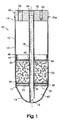
- a receiver/dryer is indicated generally at 10.
- the receiver/dryer includes a cylindrical canister 12 having a sidewall 13 with a lower closed end 14 and an upper open end 16.
- Canister 12 is preferably formed from appropriate material, such as aluminum (type 6061), and the closed lower end 14 is preferably formed in one piece with the sidewall such as by drawing, impacting or spin- forming the lower end of the sidewall.
- the lower end 14 could also be welded, brazed, soldered or attached in some other manner to the sidewall 13 such that the lower end wall is at least integral (i.e., non-removable) with the sidewall.
- the canister could also be formed from other materials, such as steel.
- the present invention is particularly suited to aluminum canisters formed in one-piece with a lower end cap or wall.
- the techniques for forming aluminum (or other metals) by the above methods are known to those skilled in the art.
- the closing operation preferably forms an annular tapered shoulder 17 between sidewall 13 and lower end 14, which will be explained herein in more detail.
- the receiver/dryer 10 includes a pick-up tube 18 which is disposed within canister 16 and extends along the central, longitudinal axis thereof.
- Pick-up tube 18 is also preferably formed from aluminum (type 3003) and has a lower downstream end 19 with a wedge or notch-shaped configuration.
- the lower end 19 of pick-up tube 18, and particularly the "point" of the wedge or notch, is disposed against the lower end 14 of the canister.
- the wedge or notched-shaped design allows fluid to enter (or exit) the hollow central bore of the pick-up tube.
- the upper end 20 of the pick-up tube has an annular channel or groove 21 formed by, e.g., roll-forming, surrounding the tube proximate end 20. Groove 21 has a depth which is sufficient to receive an elastomeric O-ring seal 22, with seal 22 projecting slightly outward from the groove in its natural or relaxed state.
- the receiver/dryer also includes a lower or downstream annular baffle 23 which supports desiccant material 24.
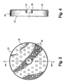
- Lower baffle 23 has a flat annular body 25 with an inner annular collar or flange 26 forming a central opening 27, and an outer annular collar or flange 28 extending around the periphery. Both the inner flange 26 and outer flange 28 extend downstream from body 25.
- Outer flange 28 preferably closely matches the inner diameter of canister sidewall 13, such that the outer flange is secured with at least a slip-fit (press-fit if possible) to the sidewall.
- the inner flange 26 also closely matches the outer diameter of the pick-up tube 18, such that the inner flange is also secured with a slip-fit (press-fit if possible) to pick-up tube 18.
- lower baffle 23 could be pre-assembled with pick-up tube 18 and could be more firmly attached, such as by coining or crimping the inner flange 26 to the pick-up tube, or by providing one or more closely-spaced annular beads on the pick-up tube to retain the baffle at a specific location.
- the baffle could also be formed without inner and/or outer flanges 26, 28, and have merely the inner diameter and outer diameter of body 25 retain the body between the pick-up tube and canister.
- baffle 23 could be staked to the pick-up tube and/or the canister, if necessary or desirable, to retain the baffle more securely between these components.
- a plurality of perforations or openings are formed in the flat body 25 of baffle 23 to allow fluid flow therethrough.
- Baffle 23 is formed from an appropriate material, for example aluminum, using conventional metal-forming techniques such as dies and stamps, or should be known to those skilled in the art.
- Filter pad 40 against the upstream surface of baffle 23, and extending between inner flange 26 and outer flange 28, is a lower annular filter pad 40.
- Filter pad 40 includes a central opening 46 which corresponds to the central opening 27 of baffle 23.
- Filter pad 40 prevents migration of desiccant material 24 through lower baffle 23, and provides filtration of refrigerant flowing therethrough.
- the lower filter pad preferably has an upstream, more porous (less dense) layer 42 in contact with the downstream surface of baffle 23, and an downstream, less porous (less dense) layer 44 facing away from baffle 23.
- Filter pad 40 is formed of an appropriate porous material, for example fiberglass, although lower baffle 23 could also be formed from such a material to filter the refrigerant, in which case the lower filter pad might not be necessary.
- Desiccant material 24 is preferably a conventional desiccant which is available from a number of sources.
- an appropriate desiccant material is manufactured by UOP under the trademarks/designations XH7 and XH9.
- Other types of desiccant material can of course be used, and it is noted that the present invention, as illustrated in Figures 6-8, is primarily directed toward a "loose-fill" desiccant, that is, a desiccant which is not contained within any bag, but is rather in a loose state and constrained only by the sidewall of the canister and the upper and lower baffles (and filter pads).
- Such loose-fill desiccant tends to be less expensive than desiccant material which is available in a bag form, although it should be apparent that desiccant in a bag form could of course be used with the present invention, although more expensive.
- the amount of desiccant necessary for the receiver/dryer depends on the particular application and can be easily determined by those skilled in the art.
- the present invention has the flexibility to use different volumes or compositions of desiccant material in a simple and easy manner by merely filling the canister to the desired level.
- the receiver/dryer is not limited to a particular volume or composition of desiccant, and can be used in different applications without having to order or stock desiccant bags of different volumes, sizes or composition.
- the upper annular baffle 44 is similar to the lower baffle 23, and includes a perforated flat body 45 preferably bounded on its inside by an inner annular flange or collar 46 and on its periphery by an outer annular flange or collar 48.
- the inner and outer flanges 46, 48 again extend downstream from body 45.
- Baffle 44 could also be formed without inner flange 46 and outer flange 48, as with the lower baffle 23.
- An upper annular filter pad 54 has a central opening and is provided against the upstream surface of baffle 44 to prevent migration of desiccant material through the baffle, and for filtration of refrigerant flowing therethrough.
- Upper baffle 44 and filter pad 54 preferably have the same configuration and are formed of the same material as lower baffle 23 and filter pad 40 illustrated in Figures 3-5 to support the upper end of the desiccant material.
- the outer annular collar 48 preferably is secured with at least a slip-fit to the inner diameter of canister 12, while the inner annular flange 46 is secured with at least a slip-fit to the pick-up tube 18.
- the inner and outer flanges of the upper baffle could also be staked to the pick-up tube and/or the canister, if necessary or desirable.
- the upper and lower baffle (and filter pads) securely hold the desiccant material to prevent undesirable movement or vibration thereof.
- An upper annular end cap 60 encloses the open upper end 16 of canister 12.
- End cap 60 preferably has a substantially flat exterior surface 62 with mounting holes 63 for mounting exterior components.
- An outlet passage 64 and an inlet passage 66 extend through the end cap.
- the outlet passage 64 is preferably disposed about the longitudinal center-line of the canister and receives the upper end 20 of the pick-up tube when assembled.
- the outlet passage and inlet passage could also be reversed in particular applications, i.e., the inlet passage could be connected to the pick-up tube, and the present invention is not intended to be limited to either passage being for "inlet” or "outlet” refrigerant flow.
- the outlet passage will be connected to the pick-up tube to direct refrigerant out of the lower end of the receiver/dryer.
- the pick-up tube 18 is received with a slip-fit within passage 64.
- the O-ring 22 at the end of the tube provides a fluid-tight seal between the pick-up tube and the end cap when the end cap is assembled to the canister, without the need for any mechanical sealing (such as by coining, crimping, etc.) to the end cap.
- the end cap is then fluidly sealed to the sidewall 13 of the canister such as by welding, brazing, soldering, etc., such as at 70a.
- canister 12 In assembling the receiver/dryer, canister 12 is initially provided with lower end cap 14 formed integrally therewith, and preferably in one piece therewith.
- Pick-up tube 18 is inserted within canister 12, with the lower end 19 of the pick-up tube contacting the closed, lower end 14 of the canister.
- the lower baffle 23 and lower filter pad 40 are received about the pick-up tube and slid down toward the lower end 19.
- the lower baffle 23 is attached to the pick-up tube by the slip-fit therewith, or alternatively, as described above, could be pre-assembled with the pick-up tube and attached thereto such as by coining or crimping, or by one or more annular beads.
- the lower baffle 23 is preferably supported at its periphery by the inwardly-tapered shoulder 17 formed at the intersection of canister 13 and lower end 14. The contact between the periphery of the lower baffle and the shoulder creates essentially a fluid-tight seal with the canister.
- the lower surface of baffle 23 faces the lower end of the receiver dryer and, together with the lower end, defines a quiescent chamber 67.
- the loose desiccant material 24 is loaded (e.g., poured) through the open end of canister 12 to fill an appropriate portion of the canister.
- the lower baffle 23 supports the lower end of the desiccant material while lower filter pad 40 prevents the desiccant from passing through the openings in the lower baffle.
- the upper filter pad 50 and upper baffle 44 are received about the pick-up tube 18 and slid down to support the upper end of the desiccant material.
- the upper filter pad 50 prevents desiccant from passing through the openings in the upper baffle, while both the upper and lower baffles (and filter pads) prevent undesirable movement or vibration of the desiccant material.
- Upper end cap 60 is then located over the open upper end 16 of the canister, with the upper end 20 of the pick-up tube 18 being received within outlet passage 64.
- the pick-up tube is forced into passage 64, with the O-ring 22 providing a fluid-tight seal therebetween.
- the fluid-tight seal created by O-ring 22 can be provided anywhere along the length of the passage 64, which allows the tolerances between these components to be greater.
- the upper end cap is then fluidly-sealed to the canister in an appropriate manner, such as by brazing, welding, soldering, etc.
- outlet and inlet passages 64, 66 are then fluidly connected within the refrigeration system in a conventional manner, and refrigerant is introduced (typically from the condenser) through the inlet passage and down through the baffles, filter pads and desiccant material to the quiescent chamber to remove water and particulate matter. Refrigerant is then drawn upward through pick-up tube and directed through the outlet passage to the refrigeration system (typically to the expansion device).
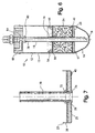
- the receiver/dryer 10 includes a desiccant tube 70 co-axial with and received around the pick-up tube 18, with the desiccant tube 70 extending between lower baffle 23 and upper baffle 44.
- Lower baffle 23 has at least a slip-fit (press-fit if possible) with desiccant tube 70.
- desiccant tube 70 have an annular bead 72 and an outwardly-turned annular flange 74 at the lower end of the desiccant tube. Bead 72 and flange 74 are spaced close together and contact opposite sides of lower baffle 23.
- bead 72 contacts the upper, radially-extending end surface of flange 26 on baffle 23, while flange 74 on desiccant tube 70 follows the curve of flange 26 and supports body 25 along the inner diameter on the lower, upstream surface of the baffle, thus securing the baffle to the desiccant tube.
- the inner diameter of the desiccant tube can be easily and closely controlled when the bead and/or flange are formed on the desiccant tube.
- End forming or flange roll forming machines can create the bead or flange and at the same time narrow the inner diameter of the tube at the location of the bead or flange.
- the inner flange 26 on the lower baffle could be roll-formed into engagement with the desiccant tube 70, or a closely-spaced pair of beads could be formed in the desiccant tube, rather than a bead and flange.
- Desiccant tube 70 and lower baffle 23 could also be formed together as one piece.
- the desiccant tube could just be roll-formed, with the inner diameter closely controlled so as to provide a press-fit with the pick-up tube when the pick-up tube is later inserted into the desiccant tube.
- end-forming, flange roll forming and roll forming machines which create such beads and flanges are conventional machinery and should be known to those skilled in the art.
- the remainder of the desiccant tube can be merely a slip-fit with the pick-up tube, which relieves tolerances and reduces fabrication costs of the desiccant tube and pick-up tube.
- lower baffle 23 and desiccant tube 70 are preferably inserted first into canister 12.
- Lower baffle 23 is preferably supported at its periphery by the shoulder 17 formed between canister sidewall 13 and the lower end 14.
- Lower filter pad 40 is then assembled with lower baffle 23.
- Desiccant 24 is then introduced into the canister and supported at its lower end by baffle 23 (and lower filter pad 40).
- the upper filter pad 50 and upper baffle 44 are then introduced into the canister and received over desiccant tube 70 to support the other end of the desiccant material 24.
- the upper baffle 44 has a sly-fit with desiccant tube 70 and can also be staked to the desiccant tube, if necessary or desirable.
- the outer periphery of lower baffle 23, has at least a slip-fit (press-fit if possible) with the canister 12, while upper baffle 44 has a slip-fit with canister 12.
- pick-up tube 18 can then be pre-assembled with end cap 60 and inserted through desiccant tube 70.
- the pick-up tube has a bead 78 at its upper end which is received within a collar 80 surrounding passage 64.
- the collar is then coined or crimped around the bead to provide a fluid-tight connection between the pick-up tube and the upper end cap.
- An O-ring (not shown) can be provided within the collar (at the upper or lower side of bead 79) to improve the fluid-tight connection.
- the pick-up tube 18 can be connected off-center to the end cap 60, and then bent or curved along the center line of the canister to be aligned with the desiccant tube 70.
- pick-up tube 18 is secured to end cap 60 in the above manner (i.e., by crimping or coining), then the lower end 19 of the pick-up tube can be spaced from the lower end 14 of the canister. This is because the upper end of the pick-up tube is attached to the end cap, which does not occur in the first aspect of the present invention.
- the pick-up tube can be secured to the upper end cap as in the first aspect, i.e., by a slip-fit with an O-ring providing the fluid-tight seal. In this case, the pick-up tube can extend downward and be supported by the lower end 14 of the canister such that the upper end of the pick-up tube is pushed up through the outlet passage in the upper end cap when assembled.
- the present invention provides a new and unique receiver/dryer and method for assembling such a receiver/dryer which is simple and cost-effective to manufacture.
- the receiver/dryer is particularly useful with loose desiccant which can be used even though the receiver/dryer has an integral lower end and must be loaded from the top.
- the receiver/dryer also has flexibility in being able to easily accommodate different volumes or compositions of desiccant material for different applications, and for allowing for the off-center connection of the pick-up tube to the end cap, without additional labor, material or costs.
Landscapes
- Chemical & Material Sciences (AREA)
- Engineering & Computer Science (AREA)
- Analytical Chemistry (AREA)
- General Chemical & Material Sciences (AREA)
- Oil, Petroleum & Natural Gas (AREA)
- Chemical Kinetics & Catalysis (AREA)
- Power Engineering (AREA)
- Physics & Mathematics (AREA)
- Mechanical Engineering (AREA)
- Thermal Sciences (AREA)
- General Engineering & Computer Science (AREA)
- Drying Of Gases (AREA)
Claims (8)
- Aufnahme/Trockner (10) mit einem Kanister (12) mit einer sich in Längsrichtung erstreckenden zylindrischen Seitenwand (13), einer integral und einstückig mit einem Ende der Seitenwand ausgebildeten ersten Endabdeckung (14) und einer Öffnung am anderen Ende (16) der Seitenwand;
einem sich in Längsrichtung in dem Kanister erstreckenden Aufnahmerohr (18 mit einem ersten Ende (19) des Aufnahmerohrs benachbart zur ersten Endabdeckung und einem zweiten Ende (20) des Aufnahmerohrs entfernt von der ersten Endabdeckung beabstandet;
einem Trockenmittelrohr (70), das in umgebender, fluiddichter Beziehung zu dem Aufnahmerohr angeordnet ist, einer ersten ringförmigen Prallfläche (23), die ein einem Innenmaß der Seitenwand nahekommendes Umfangsmaß aufweist und gegenüber dem Trockenmittelrohr fluiddicht ist, wobei die erste Prallfläche in dem Kanister benachbart zur der ersten Endabdeckung angeordnet ist;
einer zweiten ringförmigen Prallfläche (44) mit einem Umfangsmaß, das dem Innenmaß der Seitenwand nahe kommt, und einer das Trockenmittelrohr aufnehmenden mittleren Öffnung, wobei die zweite Prallfläche in dem Kanister angeordnet ist und um das Trockenmittelrohr fem der ersten Endabdeckung aufgenommen ist;
losem Trockenmittelmaterial (24), das in dem Kanister angeordnet und direkt durch die Kanisterseitenwand gelagert ist und das Trockenmittelrohr zwischen der ersten und zweiten Prallfläche umgibt;
dadurch gekennzeichnet, dass
die Aufnahme/der Trockner (10) weiterhin eine zweite Endabdeckung (60) mit ersten und zweiten Kanälen (64, 66) umfasst, die sich durch die zweite Endabdeckung erstrecken, damit das Kältemittel in den Kanister hinein und aus diesem heraus strömen kann, wobei die zweite Endabdeckung das andere Ende der Seitenwand einschließt und das zweite Ende (20) des Aufnahmerohrs in einem (64) der Kanäle (64, 66) in fluiddichter Beziehung dazu aufnimmt, und
das Trockenmittelrohr und das Aufnahmerohr einen zusammenwirkenden, mechanisch verformten Aufbau (72, 74) aufweisen, welcher eine fluiddichte Abdichtung zwischen dem Aufnahmerohr (18) und dem Trockenmittelrohr (70) erzeugt. - Aufnahme/Trockner (10) nach Anspruch 1, dadurch gekennzeichnet, dass die erste Prallfläche (23) eine das Trockenmittelrohr (70) aufnehmende mittlere Öffnung (27) aufweist und mit dem Trockenmittelrohr in Gleitpassung steht, wobei das Trockenmittetrohr ferner eine ringförmige Wulst (72) und einen ringförmigen Flansch (74) aufweist, der ringförmige Flansch (74) und die ringförmige Wulst (72) entlang des Trockenmittelrohrs beabstandet sind und entgegengesetzte Flächen der ersten Prallfläche (23) berühren, um die erste Prallfläche an dem Trockenmittelrohr zu halten, wobei ein Presssitz zwischen dem Trockenmittelrohr und dem Aufnahmerohr an dem Ort der Wulst bzw. der Flansch vorgesehen ist.
- Aufnahme/Trockner (10) nach Anspruch 2, dadurch gekennzeichnet, dass die erste Prallfläche (23) einen ringförmigen, sich radial erstreckenden Körper (25) mit einer ersten Fläche und einen die mittlere Öffnung in der ersten Prallfläche umgebenden und sich in Längsrichtung in dem Kanister weg von einer zweiten Fläche des Körpers erstreckenden Kragen (26) umfasst, wobei der Kragen eine sich radial erstreckende ringförmige Endfläche aufweist, die ringförmige Wulst des Trockenmittelrohrs mit der ringförmigen Endfläche des Trockenmittelrohrs greift und der ringförmige Flansch mit der ersten Fläche des Körpers greift, um die erste Prallfläche an dem Trockenmittelrohr zu befestigen.
- Aufnahme/Trockner (10) nach einem der vorstehenden Ansprüche, dadurch gekennzeichnet, dass der zusammenwirkende Aufbau (72, 74) eine fluiddichte Presssitzabdichtung entlang eines Teils des Trockenmittelrohrs vorsieht, wobei der Rest des Trockenmittelrohrs mit dem Aufnahmerohr in Gleitpassung steht.
- Aufnahme/Trockner (10) nach Anspruch 1, dadurch gekennzeichnet, dass das Aufnahmerohr (18) koaxial mit dem Trockenmittelrohr (70) entlang einer Längsachse des Kanisters ist und dann weg von der Längsachse gebogen und in der zweiten Endabdeckung an einem Ort weg von der Längsachse aufgenommen ist.
- Verfahren für das Montieren der Aufnahme/des Trockners (10) nach Anspruch 1, welches durch folgende Schritte gekennzeichnet ist:Vorsehen der ersten Prallfläche (23) in dichter umgebender Beziehung zu dem Trockenmittelrohr (70);Einsetzen des Trockenmittelrohrs (70) und der ersten Prallfläche (23) durch das offene Ende (16) des Kanisters (12), wobei eine erste Fläche der Prallfläche der ersten Endabdeckung (14) zugewandt ist und der Umfang der ersten Prallfläche eng in dem Kanister aufgenommen ist;anschließendes Einbringen des losen Trockenmittelmaterials (24) in den Kanister, wobei das Trockenmittelmaterial durch eine zweite Fläche der ersten Prallfläche und die Seitenwand (12) des Kanisters getragen wird;Einsetzen der zweiten Prallfläche (44) über das Trockenmittelrohr, wobei die zweite Prallfläche die das Trockenmittelrohr aufnehmende mittlere Öffnung aufweist, wobei die erste Fläche der zweiten Prallfläche das lose Trockenmittelmaterial trägt und der Umfang der zweiten Prallfläche eng in dem Behälter aufgenommen ist;Einsetzen des Aufnahmerohrs (18) durch das offene Ende (16) des Kanisters und in das Trockenmittelrohr (70) undanschließendes Anbringen der zweiten Endabdeckung (60) an dem offenen Ende des Kanisters, wobei die zweite Endabdeckung den sich durch die Endabdeckung erstreckenden ersten Kanal (64) aufweist, das Aufnahmerohr (18) in dem Kanal (64) aufgenommen ist, wobei eine fluiddichte Abdichtung zwischen dem Aufnahmerohr (18) und der zweiten Endabdeckung (60) vorgesehen ist.
- Verfahren nach Anspruch 6, welches weiterhin den Schritt des derartigen Ausbildens des Trockenmittelrohrs umfasst, dass ein Innendurchmesser vorgesehen wird, welcher mit einem Außendurchmesser des Aufnahmerohrs pressgepasst ist, wenn das Aufnahmerohr später in das Trockenmittelrohr eingesetzt wird.
- Verfahren nach einem der Ansprüche 6 oder 7, welches weiterhin den Schritt des Vormontierens der ersten Prallfläche (23) und des Trockenmittelrohrs (70) vor dem Einführen der ersten Prallfläche und des Trockenmittelrohrs in den Kanister umfasst, wobei das Trockenmittelrohr ein Paar mechanisch verformter Teile (72, 74) aufweist, welche so zusammenwirken, dass sie die erste Prallfläche an dem Trockenmittelrohr halten.
Priority Applications (1)
| Application Number | Priority Date | Filing Date | Title |
|---|---|---|---|
| EP02015772A EP1249674A3 (de) | 1996-07-31 | 1997-07-23 | Sammler/Trockner und Zusammenbauverfahren |
Applications Claiming Priority (3)
| Application Number | Priority Date | Filing Date | Title |
|---|---|---|---|
| US2283296P | 1996-07-31 | 1996-07-31 | |
| US22832P | 1996-07-31 | ||
| PCT/US1997/012885 WO1998004875A1 (en) | 1996-07-31 | 1997-07-23 | Receiver/dryer and method of assembly |
Related Child Applications (1)
| Application Number | Title | Priority Date | Filing Date |
|---|---|---|---|
| EP02015772A Division EP1249674A3 (de) | 1996-07-31 | 1997-07-23 | Sammler/Trockner und Zusammenbauverfahren |
Publications (2)
| Publication Number | Publication Date |
|---|---|
| EP0916063A1 EP0916063A1 (de) | 1999-05-19 |
| EP0916063B1 true EP0916063B1 (de) | 2003-05-21 |
Family
ID=21811666
Family Applications (1)
| Application Number | Title | Priority Date | Filing Date |
|---|---|---|---|
| EP97936174A Expired - Lifetime EP0916063B1 (de) | 1996-07-31 | 1997-07-23 | Sammler/trockner und zusammenbauverfahren |
Country Status (5)
| Country | Link |
|---|---|
| US (2) | US5910165A (de) |
| EP (1) | EP0916063B1 (de) |
| BR (1) | BR9710786A (de) |
| DE (1) | DE69722215T2 (de) |
| WO (1) | WO1998004875A1 (de) |
Families Citing this family (61)
| Publication number | Priority date | Publication date | Assignee | Title |
|---|---|---|---|---|
| US5910165A (en) * | 1996-07-31 | 1999-06-08 | Parker-Hannifin Corporation | Receiver/dryer and method of assembly |
| DE29710638U1 (de) * | 1997-06-18 | 1997-08-14 | Deutsche Controls GmbH, 80637 München | Aufnahmebehälter für eine Dessikativ-Charge |
| JPH11182986A (ja) * | 1997-12-22 | 1999-07-06 | Matsushita Electric Ind Co Ltd | 空気調和機用ドライヤー |
| GB9800146D0 (en) * | 1998-01-07 | 1998-03-04 | Boc Group Plc | Improvements in PSA systems |
| US6178772B1 (en) * | 1999-02-26 | 2001-01-30 | Multisorb Technologies, Inc. | Receiver and filter and adsorbent unit therefor |
| US6170288B1 (en) * | 1999-02-26 | 2001-01-09 | Multisorb Technologies, Inc. | Receiver and filter and adsorbent unit therefor |
| RU2153638C1 (ru) * | 1999-07-09 | 2000-07-27 | Общество с ограниченной ответственностью "Акела-Н" | Адсорбер (варианты) |
| EP1244510B1 (de) | 1999-10-07 | 2006-04-19 | Flow Dry Technology Ltd | Vorrichtung zur halterung von trocknerpatronen |
| US6623549B1 (en) | 1999-10-08 | 2003-09-23 | Stanhope Products Company | Dye wafer retention in a desiccant container |
| US6309450B1 (en) * | 1999-12-09 | 2001-10-30 | Multisorb Technologies, Inc. | Flow-through adsorbent unit assembly for receiver dryer |
| US6540842B1 (en) | 2000-01-07 | 2003-04-01 | C&M Inc. | Method for in-situ cleaning of a gas scrubber |
| US6450682B1 (en) | 2000-01-07 | 2002-09-17 | C&M Inc. | Method and apparatus for predicting the end of life of a gas scrubber |
| WO2001059373A1 (en) * | 2000-02-09 | 2001-08-16 | Parker-Hannifin Corporation | Receiver dryer with bottom inlet |
| US7127908B2 (en) * | 2000-06-05 | 2006-10-31 | Flow Dry Technology Ltd | Polypropylene or polyester plastic desiccant cartridge with fiberglass filter and bead cage ends |
| US6494059B2 (en) * | 2000-08-11 | 2002-12-17 | Showa Denko K.K. | Receiver tank for use in refrigeration cycle, heat exchanger with said receiver tank, and condensing apparatus for use in refrigeration cycle |
| US6330810B1 (en) * | 2000-08-11 | 2001-12-18 | Showa Denko K.K. | Condensing apparatus for use in a refrigeration cycle receiver-dryer used for said condensing apparatus |
| US6468334B2 (en) * | 2001-01-02 | 2002-10-22 | Multisorb Technologies, Inc. | Elongated absorbent unit with external fluid communication channels |
| GB0103762D0 (en) * | 2001-02-15 | 2001-04-04 | Air Prod & Chem | A gas purification unit |
| KR20030018495A (ko) * | 2001-08-29 | 2003-03-06 | 방경철 | 압출법을 이용한 알루미늄 리시버 튜브 일체형 리시버헤드 구조물의 제조공정. |
| US6579351B2 (en) | 2001-10-12 | 2003-06-17 | Automotive Fluid Systems, Inc. | Integrated filter and adsorbent unit for an integrated receiver-dryer and related method of manufacturing |
| US6692556B2 (en) | 2001-10-29 | 2004-02-17 | Stanhope Products Co. | Desiccant cartridge with elongated center tube |
| RU2200283C1 (ru) * | 2001-11-28 | 2003-03-10 | Общество с ограниченной ответственностью "Акела-Н" | Адсорбер |
| US6835235B2 (en) * | 2002-01-25 | 2004-12-28 | Sporlan Valve Company | Molded core filter drier with filter media molded to core for use in heat pump systems |
| US6835236B2 (en) * | 2002-01-25 | 2004-12-28 | Sporlan Valve Company | Molded core filter drier with filter media molded to core |
| US7275390B2 (en) * | 2002-04-17 | 2007-10-02 | Flow Dry Technology, Inc. | Desiccant cartridge for an integrated condenser/receiver and method of making same |
| ES2267894T3 (es) * | 2002-05-08 | 2007-03-16 | Finber S.P.A | Recipiente desecador. |
| US6615608B1 (en) * | 2002-06-26 | 2003-09-09 | Delphi Technologies, Inc. | Multi-function receiver |
| US6911065B2 (en) * | 2002-12-26 | 2005-06-28 | Matheson Tri-Gas, Inc. | Method and system for supplying high purity fluid |
| US6612122B1 (en) * | 2002-12-31 | 2003-09-02 | Kuo-Chuan Wu | Expansion valve |
| US6824596B2 (en) * | 2003-02-19 | 2004-11-30 | Jan Strmen | Gas scrubbing device for odorizing equipment operation, service and emergency |
| EP1477750A1 (de) * | 2003-05-16 | 2004-11-17 | Delphi Technologies, Inc. | Filter- und Trocknereinheit für Verflüssiger mit integriertem Sammlerkanister |
| US20050081559A1 (en) * | 2003-10-20 | 2005-04-21 | Mcgregor Ian A.N. | Accumulator with pickup tube |
| US6968713B2 (en) * | 2004-03-12 | 2005-11-29 | Halla Climate Control Canada, Inc. | Desiccant cup with integral filter |
| EP1725319A4 (de) * | 2004-03-19 | 2008-04-02 | Illinois Tool Works | Luft-/gastrockner mit entsorgbarer patrone |
| US20060196219A1 (en) * | 2005-03-01 | 2006-09-07 | Halla Climate Control Canada Inc. | Accumulator with full-flow filtering |
| US8435224B2 (en) * | 2005-09-12 | 2013-05-07 | Abela Pharmaceuticals, Inc. | Materials for facilitating administration of dimethyl sulfoxide (DMSO) and related compounds |
| JP5399072B2 (ja) * | 2005-09-12 | 2014-01-29 | アベラ ファーマスーティカルズ インコーポレイテッド | ジメチルスルホキシド(dmso)若しくは関連化合物、又はそれに関連する臭気を除去するシステム |
| EP2324838A1 (de) * | 2005-09-12 | 2011-05-25 | Abela Pharmaceuticals, Inc. | Zusammensetzungen mit Dimethyl-Sulfoxid |
| US8480797B2 (en) | 2005-09-12 | 2013-07-09 | Abela Pharmaceuticals, Inc. | Activated carbon systems for facilitating use of dimethyl sulfoxide (DMSO) by removal of same, related compounds, or associated odors |
| US7416586B1 (en) * | 2005-10-18 | 2008-08-26 | Rix Industries | Filter apparatus for extracting water vapors from a gas |
| US20070251256A1 (en) * | 2006-03-20 | 2007-11-01 | Pham Hung M | Flash tank design and control for heat pumps |
| WO2007133447A1 (en) * | 2006-05-09 | 2007-11-22 | Flow Dry Technology, Inc. | Desiccant bag and filter assembly |
| US20090250390A1 (en) * | 2007-01-24 | 2009-10-08 | Wix Filtration Corp Llc | Filter |
| DE102007009760A1 (de) | 2007-02-27 | 2008-09-04 | Danfoss A/S | Trockner-Filter-Einheit für Kältemittelkreisläufe |
| US20080229605A1 (en) * | 2007-03-23 | 2008-09-25 | Brown Jerome R | Gas drying assembly with cartridge and method |
| BRPI0921494A2 (pt) | 2008-11-03 | 2018-10-30 | Prad Reasearch And Development Ltd | método de planejamento de uma operação de amostragem para uma formação subterrãnea, método de contolar uma operação de amostragem de formação subterrânea, método de controlar uma operação de perfuração para uma formação subterrãnea, e método de realizar uma amostragem durante a operação de perfuração. |
| DE102009049546A1 (de) * | 2009-10-16 | 2011-04-21 | Hydac Filtertechnik Gmbh | Vorrichtung zum Trocknen eines Medienstroms |
| AU2010313253B2 (en) | 2009-10-30 | 2015-02-19 | Abela Pharmaceuticals, Inc. | Dimethyl sulfoxide (DMSO) and methylsulfonylmethane (MSM) formulations to treat osteoarthritis |
| DE102010037099B4 (de) * | 2010-08-21 | 2013-11-14 | Naeck Industrietechnik Gmbh | Aufnahmeanordnung für ein Adsorbens |
| CN201852383U (zh) | 2010-11-17 | 2011-06-01 | 浙江三花汽车控制系统有限公司 | 一种热交换器及其贮液器 |
| US8828126B2 (en) * | 2011-02-04 | 2014-09-09 | Leco Corporation | Removable final scrubber tube |
| CN104607004A (zh) * | 2015-01-21 | 2015-05-13 | 南通奥特机械设备有限公司 | 一种天然气干燥器 |
| DE102015203601A1 (de) | 2015-02-27 | 2016-09-01 | Mahle International Gmbh | Trockner |
| JP6397989B2 (ja) * | 2015-03-12 | 2018-09-26 | 東京濾器株式会社 | オイルミストフィルタ及びオイルセパレータ |
| US10300425B2 (en) | 2016-09-23 | 2019-05-28 | Arrow Pneumatics, Inc. | Apparatus for removing oil and moisture from a gas |
| FR3074273B1 (fr) * | 2017-11-28 | 2020-01-17 | Valeo Systemes Thermiques | Bouteille deshydratante pour un circuit de fluide refrigerant equipant un vehicule, notamment automobile. |
| WO2019128761A1 (zh) | 2017-12-25 | 2019-07-04 | 浙江三花汽车零部件有限公司 | 一种贮液器及其制造方法 |
| EP3855101B1 (de) * | 2020-01-22 | 2023-05-17 | Valeo Autosystemy SP. Z.O.O. | Wärmetauscher mit horizontal positioniertem sammler-trockner |
| DE102020132276A1 (de) | 2020-12-04 | 2022-06-09 | Zf Cv Systems Europe Bv | Lufttrockner |
| US11123678B2 (en) | 2021-05-04 | 2021-09-21 | GPL Odorizers LLC | Air filtration device |
| FR3167432A1 (fr) * | 2024-10-11 | 2026-04-17 | Valeo Systemes Thermiques | Bouteille déshydratante |
Family Cites Families (60)
| Publication number | Priority date | Publication date | Assignee | Title |
|---|---|---|---|---|
| US1439151A (en) * | 1921-10-13 | 1922-12-19 | Charles E Dailey | Air filter |
| US1726805A (en) * | 1926-08-25 | 1929-09-03 | C & C Engineering Co Inc | Combination valve, drier, and strainer |
| US1743877A (en) * | 1926-11-12 | 1930-01-14 | Superheater Co Ltd | High-pressure drum and method for making it |
| US1809834A (en) * | 1927-03-25 | 1931-06-16 | Chicago Pneumatic Tool Co | Method and means for stabilizing the atmosphere of refrigerating systems |
| US1839350A (en) * | 1929-07-29 | 1932-01-05 | Fedders Mfg Co Inc | Dehydrator |
| US2043298A (en) * | 1932-06-21 | 1936-06-09 | Markels Leonard | Apparatus for arresting sparks and purifying exhaust gases |
| US2225990A (en) * | 1937-12-22 | 1940-12-24 | Guy J Henry | Dehydrator |
| US2504184A (en) * | 1947-08-13 | 1950-04-18 | Henry Valve Company Inc | Combination drier and accumulator |
| US2705405A (en) * | 1949-12-16 | 1955-04-05 | Thomas L Uhlman | Cleaner for refrigeration apparatus |
| US2758719A (en) * | 1953-01-22 | 1956-08-14 | Ansul Chemical Co | Dehydrator |
| US2835114A (en) * | 1956-03-23 | 1958-05-20 | Philco Corp | Refrigeration apparatus |
| US3029581A (en) * | 1957-03-25 | 1962-04-17 | Robbins Aviat Inc | Desiccating apparatus |
| US2958105A (en) * | 1958-11-28 | 1960-11-01 | Glen R Morton | Flowable material separator for the vacuum system of vacuum casting equipment |
| DE1139518B (de) * | 1959-10-29 | 1962-11-15 | Hansa Metallwerke Ag | Sammelflasche fuer das vom Verfluessiger einer Kompressionskaelteanlage kommende fluessige Kaeltemittel |
| US3146602A (en) * | 1961-12-05 | 1964-09-01 | Electronic Specialty Co | Process and apparatus for eliminating fixed gas from an absorption refrigeration system |
| US3545227A (en) * | 1969-01-06 | 1970-12-08 | Darwin R Grahl | Receiver-dryer for refrigeration systems |
| US3785164A (en) * | 1972-05-17 | 1974-01-15 | Virginia Chemicals Inc | Precharged receiver drier for automobile air conditioning systems |
| US4118323A (en) * | 1974-06-11 | 1978-10-03 | Yamakawa Industry Co. Ltd. | Strainer |
| JPS5338052A (en) * | 1976-09-21 | 1978-04-07 | Hinode Kisen Co Ltd | Ball slider for moving heavy article |
| US4288894A (en) * | 1979-09-24 | 1981-09-15 | Greer Hydraulics, Incorporated | Method of manufacturing pressure vessels by heat forming |
| US4291548A (en) * | 1980-07-07 | 1981-09-29 | General Motors Corporation | Liquid accumulator |
| US4331001A (en) * | 1981-05-11 | 1982-05-25 | General Motors Corporation | Accumulator-dehydrator assembly for an air conditioning system |
| US4364756A (en) * | 1981-07-07 | 1982-12-21 | Virginia Chemicals Inc. | Refrigerant suction line filter/filter-drier and method for the construction thereof |
| US4436623A (en) * | 1982-07-28 | 1984-03-13 | Multiform Desiccants, Inc. | Adsorbent cartridge |
| US4496378A (en) * | 1982-12-16 | 1985-01-29 | Murray Corporation | Accumulator dehydrator |
| US4707999A (en) * | 1985-02-25 | 1987-11-24 | Nippondenso Co., Ltd. | Receiver for refrigerant apparatus |
| JPH045975Y2 (de) * | 1985-03-26 | 1992-02-19 | ||
| DE3543206A1 (de) * | 1985-12-06 | 1987-06-11 | Bellino Emaillier Stanz Metal | Trocknerbehaelter fuer klima- und/oder kuehlanlagen |
| IT207969Z2 (it) * | 1986-09-04 | 1988-03-14 | Kenmore Spa | Dispositivo di filtraggio per circuiti frigorigeni. |
| US4745772A (en) * | 1987-04-20 | 1988-05-24 | Ferris James E | Air conditioner auxiliary filter/drier refrigerant and chemical additive transfer device |
| US4756166A (en) * | 1987-11-13 | 1988-07-12 | General Motors Corporation | Integral receiver/dehydrator and expansion valve for air conditioning systems |
| US5048309A (en) * | 1987-12-30 | 1991-09-17 | Carlisle Jr Billy M | Universal accumulator |
| US4788833A (en) * | 1988-02-18 | 1988-12-06 | Frigette Corporation | Drier for air conditioning system |
| US4838901A (en) * | 1988-05-17 | 1989-06-13 | Life Systems, Inc. | Lightweight filter |
| JPH0271067A (ja) * | 1988-09-05 | 1990-03-09 | Showa Alum Corp | 受液器 |
| JPH0264855U (de) * | 1988-10-31 | 1990-05-16 | ||
| JPH0648283Y2 (ja) * | 1989-03-13 | 1994-12-12 | カルソニック株式会社 | リキッドタンク |
| US4908132A (en) * | 1989-07-26 | 1990-03-13 | Parker Hannifin Corporation | Shock resistant receiver dehydrator |
| US5110330A (en) * | 1990-02-08 | 1992-05-05 | Arrow Pneumatics, Inc. | Filter dryer |
| US5398523A (en) * | 1990-11-30 | 1995-03-21 | Sanden Corporation | Receiver dryer for a refrigeration circuit |
| US5304235A (en) * | 1991-04-04 | 1994-04-19 | Toyo Roki Seizo Kabushikikaisha | Canister |
| US5403387A (en) * | 1991-09-06 | 1995-04-04 | Reading Technologies, Inc. | Apparatus for removing moisture from a gas |
| US5179780A (en) * | 1991-11-12 | 1993-01-19 | General Motors Corporation | Universal seamless receiver-dehydrator assembly for an automotive air conditioning system |
| US5215660A (en) * | 1992-01-29 | 1993-06-01 | Parker Hannifin Corporation | Filter drier for refrigeration system |
| US5247813A (en) * | 1992-02-24 | 1993-09-28 | Bottum Edward W | Suction accumulator and sight glass structure associated therewith |
| US5201195A (en) * | 1992-04-27 | 1993-04-13 | General Motors Corporation | Bi-flow receiver/dehydrator for refrigeration system |
| US5245842A (en) * | 1992-05-01 | 1993-09-21 | Fayette Tubular Technology Corporation | Receiver dryer |
| US5289697A (en) * | 1992-10-28 | 1994-03-01 | Eaton Corporation | Refrigerant receiver/drier |
| DE4319293C2 (de) * | 1993-06-10 | 1998-08-27 | Behr Gmbh & Co | Kondensator für eine Klimaanlage |
| US5365751A (en) * | 1993-09-13 | 1994-11-22 | General Motors Corporation | Universal accumulator dehydrator assembly |
| US5425250A (en) * | 1994-02-25 | 1995-06-20 | Eaton Corporation | Receiver/dryer |
| US5435153A (en) * | 1994-03-16 | 1995-07-25 | Eaton Corporation | Receiver/drier |
| US5415014A (en) * | 1994-03-21 | 1995-05-16 | Thermo King Corporation | Refrigerant receiver tank assembly |
| US5569316A (en) * | 1995-03-01 | 1996-10-29 | Stanhope Products Company | Desiccant container having mount for canister tube and inner wall extension portion |
| US5596882A (en) * | 1995-03-13 | 1997-01-28 | Eaton Corporation | Receiver for refrigerant and method of making same |
| US5580451A (en) * | 1995-05-01 | 1996-12-03 | Automotive Fluid Systems, Inc. | Air conditioning refrigerant fluid dryer assembly |
| US5716432A (en) * | 1996-02-12 | 1998-02-10 | Stanhope Products Company | Desiccant container |
| US5718743A (en) * | 1996-02-26 | 1998-02-17 | Multisorb Technologies, Inc. | Desiccant cartridge |
| US5910165A (en) * | 1996-07-31 | 1999-06-08 | Parker-Hannifin Corporation | Receiver/dryer and method of assembly |
| US5689893A (en) * | 1996-09-13 | 1997-11-25 | Westinghouse Air Brake Company | Desiccant canister with positioning bore |
-
1997
- 1997-07-14 US US08/892,379 patent/US5910165A/en not_active Expired - Lifetime
- 1997-07-23 WO PCT/US1997/012885 patent/WO1998004875A1/en not_active Ceased
- 1997-07-23 EP EP97936174A patent/EP0916063B1/de not_active Expired - Lifetime
- 1997-07-23 BR BR9710786A patent/BR9710786A/pt not_active IP Right Cessation
- 1997-07-23 DE DE69722215T patent/DE69722215T2/de not_active Expired - Lifetime
-
1998
- 1998-09-10 US US09/150,187 patent/US6106596A/en not_active Expired - Lifetime
Also Published As
| Publication number | Publication date |
|---|---|
| US5910165A (en) | 1999-06-08 |
| DE69722215T2 (de) | 2003-11-27 |
| DE69722215D1 (de) | 2003-06-26 |
| BR9710786A (pt) | 1999-08-17 |
| WO1998004875A1 (en) | 1998-02-05 |
| EP0916063A1 (de) | 1999-05-19 |
| US6106596A (en) | 2000-08-22 |
Similar Documents
| Publication | Publication Date | Title |
|---|---|---|
| US6106596A (en) | Receiver/dryer and method of assembly | |
| EP0674143B1 (de) | Sammelgefäss/Trockner mit integrierter Anschlussplatte | |
| JPH0648283Y2 (ja) | リキッドタンク | |
| US5289697A (en) | Refrigerant receiver/drier | |
| US6389843B2 (en) | Receiver dryer with bottom inlet | |
| US6170287B1 (en) | Desiccant installation for refrigerant condenser with integral receiver | |
| US5651266A (en) | Drier/accumulator for refrigerant system and method of making same | |
| EP0704662B1 (de) | Wärmeaustauscher mit integraler Trocknungsfilterpatrone | |
| US5774982A (en) | Conduit attachment to receiver/drier or accumulator | |
| JPS603433Y2 (ja) | 冷媒アキユムレ−タ | |
| US5904055A (en) | Accumulator deflector having a plastic bushing | |
| EP1249674A2 (de) | Sammler/Trockner und Zusammenbauverfahren | |
| EP1497596B1 (de) | Trocknungsmittelpatrone für einen integrierten verflüssiger/sammler und herstellungsverfahren dafür | |
| JPH085202A (ja) | 空調システム用アキュムレータ | |
| KR100976130B1 (ko) | 리시버 드라이어를 구비한 열교환기 및, 그것의 제조 방법 | |
| US5425250A (en) | Receiver/dryer | |
| KR100483107B1 (ko) | 리시버/건조기 및 조립 방법 | |
| EP1464902A2 (de) | Trocknerabstandshalter in einem Verdichterbehälter einer Kraftfahrzeugklimaanlage | |
| US7275392B2 (en) | Internal cage tube bag | |
| JP4014781B2 (ja) | アキュムレータ | |
| JPH10318631A (ja) | 受液器の製造方法 | |
| WO1998011396A1 (en) | Accumulator deflector having a plastic bushing | |
| JPH04113865U (ja) | リキツドタンク | |
| JP2003106792A (ja) | 熱交換器 |
Legal Events
| Date | Code | Title | Description |
|---|---|---|---|
| PUAI | Public reference made under article 153(3) epc to a published international application that has entered the european phase |
Free format text: ORIGINAL CODE: 0009012 |
|
| 17P | Request for examination filed |
Effective date: 19990211 |
|
| AK | Designated contracting states |
Kind code of ref document: A1 Designated state(s): DE FR GB IT |
|
| RIN1 | Information on inventor provided before grant (corrected) |
Inventor name: WILSON, TOM, C. Inventor name: FORD, MICHAEL, L. Inventor name: HARAMOTO, CARY |
|
| 17Q | First examination report despatched |
Effective date: 20010328 |
|
| GRAH | Despatch of communication of intention to grant a patent |
Free format text: ORIGINAL CODE: EPIDOS IGRA |
|
| GRAH | Despatch of communication of intention to grant a patent |
Free format text: ORIGINAL CODE: EPIDOS IGRA |
|
| GRAA | (expected) grant |
Free format text: ORIGINAL CODE: 0009210 |
|
| AK | Designated contracting states |
Designated state(s): DE FR GB IT |
|
| REG | Reference to a national code |
Ref country code: GB Ref legal event code: FG4D |
|
| REF | Corresponds to: |
Ref document number: 69722215 Country of ref document: DE Date of ref document: 20030626 Kind code of ref document: P |
|
| ET | Fr: translation filed | ||
| PLBE | No opposition filed within time limit |
Free format text: ORIGINAL CODE: 0009261 |
|
| STAA | Information on the status of an ep patent application or granted ep patent |
Free format text: STATUS: NO OPPOSITION FILED WITHIN TIME LIMIT |
|
| 26N | No opposition filed |
Effective date: 20040224 |
|
| REG | Reference to a national code |
Ref country code: FR Ref legal event code: PLFP Year of fee payment: 20 |
|
| PGFP | Annual fee paid to national office [announced via postgrant information from national office to epo] |
Ref country code: DE Payment date: 20160726 Year of fee payment: 20 Ref country code: GB Payment date: 20160727 Year of fee payment: 20 Ref country code: IT Payment date: 20160722 Year of fee payment: 20 |
|
| PGFP | Annual fee paid to national office [announced via postgrant information from national office to epo] |
Ref country code: FR Payment date: 20160726 Year of fee payment: 20 |
|
| REG | Reference to a national code |
Ref country code: DE Ref legal event code: R071 Ref document number: 69722215 Country of ref document: DE |
|
| REG | Reference to a national code |
Ref country code: GB Ref legal event code: PE20 Expiry date: 20170722 |
|
| PG25 | Lapsed in a contracting state [announced via postgrant information from national office to epo] |
Ref country code: GB Free format text: LAPSE BECAUSE OF EXPIRATION OF PROTECTION Effective date: 20170722 |