EP0918206A2 - Splitterhülle für Munition - Google Patents
Splitterhülle für Munition Download PDFInfo
- Publication number
- EP0918206A2 EP0918206A2 EP98121469A EP98121469A EP0918206A2 EP 0918206 A2 EP0918206 A2 EP 0918206A2 EP 98121469 A EP98121469 A EP 98121469A EP 98121469 A EP98121469 A EP 98121469A EP 0918206 A2 EP0918206 A2 EP 0918206A2
- Authority
- EP
- European Patent Office
- Prior art keywords
- splinter
- shell
- rings
- splinters
- casing
- Prior art date
- Legal status (The legal status is an assumption and is not a legal conclusion. Google has not performed a legal analysis and makes no representation as to the accuracy of the status listed.)
- Granted
Links
- 238000013467 fragmentation Methods 0.000 title description 5
- 238000006062 fragmentation reaction Methods 0.000 title description 5
- 239000012634 fragment Substances 0.000 claims abstract description 23
- 239000000853 adhesive Substances 0.000 claims abstract description 10
- 230000001070 adhesive effect Effects 0.000 claims abstract description 10
- 239000000463 material Substances 0.000 claims abstract description 9
- 229910001385 heavy metal Inorganic materials 0.000 claims abstract description 3
- 206010041662 Splinter Diseases 0.000 claims description 40
- 239000002360 explosive Substances 0.000 claims description 7
- 239000011230 binding agent Substances 0.000 claims description 5
- 229910000831 Steel Inorganic materials 0.000 claims description 3
- 229910052751 metal Inorganic materials 0.000 claims description 3
- 239000002184 metal Substances 0.000 claims description 3
- 239000010959 steel Substances 0.000 claims description 3
- 238000005474 detonation Methods 0.000 description 3
- 238000000034 method Methods 0.000 description 3
- 229910052845 zircon Inorganic materials 0.000 description 2
- GFQYVLUOOAAOGM-UHFFFAOYSA-N zirconium(iv) silicate Chemical compound [Zr+4].[O-][Si]([O-])([O-])[O-] GFQYVLUOOAAOGM-UHFFFAOYSA-N 0.000 description 2
- 230000006978 adaptation Effects 0.000 description 1
- 229910052782 aluminium Inorganic materials 0.000 description 1
- XAGFODPZIPBFFR-UHFFFAOYSA-N aluminium Chemical compound [Al] XAGFODPZIPBFFR-UHFFFAOYSA-N 0.000 description 1
- 230000005540 biological transmission Effects 0.000 description 1
- 230000001419 dependent effect Effects 0.000 description 1
- 238000011161 development Methods 0.000 description 1
- 230000018109 developmental process Effects 0.000 description 1
- 230000002349 favourable effect Effects 0.000 description 1
- 239000000945 filler Substances 0.000 description 1
- 238000007493 shaping process Methods 0.000 description 1
- 230000035939 shock Effects 0.000 description 1
- UONOETXJSWQNOL-UHFFFAOYSA-N tungsten carbide Chemical compound [W+]#[C-] UONOETXJSWQNOL-UHFFFAOYSA-N 0.000 description 1
Images

Classifications
-
- F—MECHANICAL ENGINEERING; LIGHTING; HEATING; WEAPONS; BLASTING
- F42—AMMUNITION; BLASTING
- F42B—EXPLOSIVE CHARGES, e.g. FOR BLASTING, FIREWORKS, AMMUNITION
- F42B12/00—Projectiles, missiles or mines characterised by the warhead, the intended effect, or the material
- F42B12/02—Projectiles, missiles or mines characterised by the warhead, the intended effect, or the material characterised by the warhead or the intended effect
- F42B12/20—Projectiles, missiles or mines characterised by the warhead, the intended effect, or the material characterised by the warhead or the intended effect of high-explosive type
- F42B12/22—Projectiles, missiles or mines characterised by the warhead, the intended effect, or the material characterised by the warhead or the intended effect of high-explosive type with fragmentation-hull construction
- F42B12/28—Projectiles, missiles or mines characterised by the warhead, the intended effect, or the material characterised by the warhead or the intended effect of high-explosive type with fragmentation-hull construction the projectile wall being built from annular elements
-
- F—MECHANICAL ENGINEERING; LIGHTING; HEATING; WEAPONS; BLASTING
- F42—AMMUNITION; BLASTING
- F42B—EXPLOSIVE CHARGES, e.g. FOR BLASTING, FIREWORKS, AMMUNITION
- F42B12/00—Projectiles, missiles or mines characterised by the warhead, the intended effect, or the material
- F42B12/02—Projectiles, missiles or mines characterised by the warhead, the intended effect, or the material characterised by the warhead or the intended effect
- F42B12/20—Projectiles, missiles or mines characterised by the warhead, the intended effect, or the material characterised by the warhead or the intended effect of high-explosive type
- F42B12/22—Projectiles, missiles or mines characterised by the warhead, the intended effect, or the material characterised by the warhead or the intended effect of high-explosive type with fragmentation-hull construction
- F42B12/26—Projectiles, missiles or mines characterised by the warhead, the intended effect, or the material characterised by the warhead or the intended effect of high-explosive type with fragmentation-hull construction the projectile wall being formed by a spirally-wound element
Definitions
- the invention relates to a fragmentation shell for ammunition according to the preamble of claim 1.
- the invention has for its object to provide measures in a splinter shell, the fragment sizes largely defined when the explosive detonates leads.
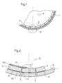
- a shell 1 shows in its inner wall 2 plate-shaped, sharp-edged splinters 3 made of heavy metal or high-strength steel
- the splitters 3 are by a Pressing process molded into the inner wall 2.
- the shell is subject to 1 - starting from the edges 4 - stress zones 5.
- the advantage is also achieved that Stress zones 5 the shaping of the projectile shell 1 into fragments takes place more quickly and less energy is required for fragmentation from the shell 1.
- An adhesive 7 serves as an additional fastening means for the splitters 3 with one another and for the splitter 3 for attachment to the shell 1 view is sufficient for the attachment of the splinters 3 on the projectile casing 1 the impression.
- the adhesive 7 also serves to increase the fragmentation speed in which the Cavities 7 are filled by the adhesive 7. An energy consuming deformation the splinter 3 is blown into the cavities 9,9.1,9.2 by the explosive pressure largely avoided.
- the splitters 3 according to FIG. 2 are either individual splitters, notched on their outer side 13 Splinter rings or 13 notched fragment spirals 24 on their outside.
- the embedding material for the splitters 3 or split rings 10 or split helix 11, which is designated as adhesive 7, corresponds or largely corresponds to that Density and strength of the fragments 3 or the fragment rings 10 or the fragment spiral 11.
- the embedding material or filler material therefore has the same shock wave impedance, like the splinters 3 on.
- This is characterized by an embedding material Tungsten carbide, optionally with a binder component or by adding a metal component reached in a binder.
- the cavities 9, 9.1, 9.2 between the splitters 3 with one another or between the splinters 3, the splinter rings 10, the splinter spiral 11 relative to the splinter shirt 8 or the fragment cover 1 are with the adhesive 7 or an embedding material, filled in as described above.
- An energy consuming deformation of the Splitter 3 or the not shown splitter of the pre-notched splinter rings 10 or the fragment spiral 11 into the cavities 9, 9.1, 9.2 largely avoided. This will significantly increase the fragmentation speed reached.
- hard splinters 3 which are harder than the shell 1 is due to Pre-notching, i.e. partial deformation, in the pressing process or calibration process in the edge area of the shell 1 before.
- a fragment ring 10 or a fragment spiral 11 on their the explosive charge facing inside 6 according to FIG. 5 notches 12 on the the disassembly of the fragment rings 10 or the assembled into a package Favor fragment spiral 11 to individual fragments.
- the sharp-edged splinter rings 10 and the fragment helix 11 are calibrated after it has been introduced into the projectile casing 1, so that after calibration ring-shaped tension zones 5 arise in the projectile casing 1 and / or caused by the explosive pressure in the shell 1.
Landscapes
- Engineering & Computer Science (AREA)
- Chemical & Material Sciences (AREA)
- Combustion & Propulsion (AREA)
- General Engineering & Computer Science (AREA)
- Aiming, Guidance, Guns With A Light Source, Armor, Camouflage, And Targets (AREA)
- Earth Drilling (AREA)
Abstract
Description
- Fig. 1
- einen Teilquerschnitt durch eine Splitterhülle eines Geschosses,
- Fig. 2
- eine vergrößert gezeichnete Einzelheit II nach Fig. 1,
- Fig. 3,4
- einen vorgekerbten Splitterring und eine Splitterwendel in der Ansicht und
- Fig. 5
- in gestreckter Darstellung einen vergrößert gezeichneten Ausschnitt V nach den Fig. 3, 4.
Claims (7)
- Splitterhülle (1) für Munition, wie Geschosse, Gefechtsköpfe, Handgranaten mit sprengstoffbeschleunigten Splittern (3) innerhalb einer Hülle (1),
dadurch gekennzeichnet,
daß die scharfkantig ausgebildeten Splitter (3) bzw. paketförmig hintereinander angeordneten Splitterringe (10) bzw. eine Splitterwendel (11) in der, in Splitter zerlegbaren Hülle (1) aus Stahl eingeprägt oder eingeformt sind oder mindestens linienförmig unter Vorspannung an der Hülle (1) anliegen. - Splitterhülle nach Anspruch 1,
dadurch gekennzeichnet,
daß die vorgefertigten Splitter (3) zusätzlich durch einen Klebstoff (7) untereinander und mit der Hülle (1) verbunden sind. - Splitterhülle nach Anspruch 2,
dadurch gekennzeichnet,
daß der Kleber (7) bzw. das Einbettungsmaterial für die Splitter (3), Splitterringe (10), Splitterwendel (11) eine Dichte und Festigkeit der Splitter (3), der Splitterringe (10), der Splitterwendel (11) aufweist. - Splitterhülle nach Anspruch 3,
dadurch gekennzeichnet,
daß der Kleber (7) bzw. Einbettungsmaterial für die Splitter (3), Splitterringe (10), Splitterwendel (11) aus Hartmetall mit Binder, Metallanteil, wie Späne im Binder oder Schwermetallanteile im Binder besteht. - Splitterhülle nach Anspruch 1,
dadurch gekennzeichnet,
daß die Härte der Splitter (3), Splitterringe (10), Splitterwendel (11) härter ist, als die Härte der Splitterhülle (1). - Splitterhülle nach Anspruch 1,
dadurch gekennzeichnet,
daß die Härte der Splitter (3), Splitterringe (10), Splitterwendel (11) der Härte der Splitterhülle (1) entspricht. - Splitterhülle nach Anspruch 1,
dadurch gekennzeichnet,
daß die Splitterhülle (1) härter ist als die Splitter (3), Splitterringe (10), Splitterwendel (11).
Applications Claiming Priority (2)
| Application Number | Priority Date | Filing Date | Title |
|---|---|---|---|
| DE19753188 | 1997-11-21 | ||
| DE19753188A DE19753188C2 (de) | 1997-11-21 | 1997-11-21 | Splitterbildende Hülle für Munition |
Publications (3)
| Publication Number | Publication Date |
|---|---|
| EP0918206A2 true EP0918206A2 (de) | 1999-05-26 |
| EP0918206A3 EP0918206A3 (de) | 1999-12-15 |
| EP0918206B1 EP0918206B1 (de) | 2003-08-20 |
Family
ID=7850353
Family Applications (1)
| Application Number | Title | Priority Date | Filing Date |
|---|---|---|---|
| EP98121469A Expired - Lifetime EP0918206B1 (de) | 1997-11-21 | 1998-11-11 | Splitterhülle für Munition |
Country Status (3)
| Country | Link |
|---|---|
| EP (1) | EP0918206B1 (de) |
| DE (2) | DE19753188C2 (de) |
| ES (1) | ES2206811T3 (de) |
Cited By (3)
| Publication number | Priority date | Publication date | Assignee | Title |
|---|---|---|---|---|
| WO2001079781A1 (de) * | 2000-04-19 | 2001-10-25 | Karl Merz | Stahlmantel für eine granate und verfahren zu seiner herstellung |
| FR2840402A1 (fr) | 2002-05-31 | 2003-12-05 | Giat Ind Sa | Enveloppe generatrice d'eclats, charge explosive et munition mettant en oeuvre une telle enveloppe |
| EP1971818A4 (de) * | 2006-01-13 | 2012-01-04 | Bae Systems Bofors Ab | Verfahren zum auslösen von sprengladungen und sprengladungsgeladene betätigungselemente dafür |
Families Citing this family (7)
| Publication number | Priority date | Publication date | Assignee | Title |
|---|---|---|---|---|
| RU2183815C2 (ru) * | 2000-08-14 | 2002-06-20 | ФГУП "ГосНИИМаш" | Боевая часть |
| RU2183814C2 (ru) * | 2000-08-14 | 2002-06-20 | ФГУП "ГосНИИМаш" | Способ дробления наружной цельнометаллической оболочки боевой части |
| DE10208228B4 (de) * | 2002-02-26 | 2005-03-17 | Diehl Munitionssysteme Gmbh & Co. Kg | Blastgranate |
| RU2227265C1 (ru) * | 2003-03-24 | 2004-04-20 | Владыкин Эдуард Иванович | Боевая часть |
| RU2228509C1 (ru) * | 2003-03-24 | 2004-05-10 | Владыкин Эдуард Иванович | Боевая часть (варианты) |
| DE102007048040A1 (de) | 2007-10-05 | 2009-04-09 | Rheinmetall Waffe Munition Gmbh | Gehäusematerial für ein Sprenggeschoss, eine Handgranate oder dergleichen |
| RU2705134C1 (ru) * | 2019-02-14 | 2019-11-05 | Федеральное государственное военное казённое образовательное учреждение высшего образования "Военная академия материально-технического обеспечения имени генерала армии А.В. Хрулёва" Министерства обороны Российской Федерации | Боеприпас осколочного действия с готовыми поражающими элементами |
Citations (1)
| Publication number | Priority date | Publication date | Assignee | Title |
|---|---|---|---|---|
| US4381692A (en) | 1977-05-11 | 1983-05-03 | Quantic Industries, Inc. | Method of making an incendiary munition |
Family Cites Families (15)
| Publication number | Priority date | Publication date | Assignee | Title |
|---|---|---|---|---|
| FR1077997A (fr) * | 1952-09-29 | 1954-11-15 | Projectiles | |
| US3298308A (en) * | 1960-11-11 | 1967-01-17 | Aerojet General Co | Composite casing for fragmentationtype explosive weapon and method of forming same |
| BE686286A (de) * | 1966-09-01 | 1967-02-15 | ||
| US3580175A (en) * | 1968-09-19 | 1971-05-25 | Gerity Schultz Corp | Fragmentation explosive device |
| FR2312009A1 (fr) * | 1975-05-23 | 1976-12-17 | Thomson Brandt | Enveloppe de charge explosive et notamment projectile a fragmentation |
| DE2557676A1 (de) * | 1975-12-20 | 1977-06-30 | Diehl Fa | Splittergeschoss |
| DE2852657C2 (de) * | 1978-12-06 | 1984-10-04 | Diehl GmbH & Co, 8500 Nürnberg | Splitterkörper für Splittergeschosse |
| DE2852659A1 (de) * | 1978-12-06 | 1980-06-19 | Diehl Gmbh & Co | Verfahren zur herstellung metallischer formkoerper |
| DE2852658A1 (de) * | 1978-12-06 | 1980-06-12 | Diehl Gmbh & Co | Verfahren zur herstellung metallischer formkoerper |
| GB2167537B (en) * | 1984-11-13 | 1987-12-23 | Anthony Mario Caruso | Anti-personnel fragmentation liner |
| DE3722023A1 (de) * | 1987-07-03 | 1989-01-12 | Rheinmetall Gmbh | Geschoss mit sprengladung |
| FR2617955B1 (fr) * | 1987-07-08 | 1993-11-26 | Alsetex Armement Etudes Sae | Projectile explosif a enveloppe prefragmentee d'efficacite accrue et procede de realisation |
| FR2684753A1 (fr) * | 1991-12-04 | 1993-06-11 | Sassier Pierre Henri | Enveloppe prefabriquee pour grenade. |
| US5337673A (en) * | 1993-12-17 | 1994-08-16 | The United States Of America As Represented By The Secretary Of The Navy | Controlled fragmentation warhead case |
| FR2730558B1 (fr) * | 1995-02-14 | 1997-03-14 | Tda Armements Sas | Charge a generateur d'eclats ameliore |
-
1997
- 1997-11-21 DE DE19753188A patent/DE19753188C2/de not_active Expired - Fee Related
-
1998
- 1998-11-11 ES ES98121469T patent/ES2206811T3/es not_active Expired - Lifetime
- 1998-11-11 DE DE59809335T patent/DE59809335D1/de not_active Expired - Fee Related
- 1998-11-11 EP EP98121469A patent/EP0918206B1/de not_active Expired - Lifetime
Patent Citations (1)
| Publication number | Priority date | Publication date | Assignee | Title |
|---|---|---|---|---|
| US4381692A (en) | 1977-05-11 | 1983-05-03 | Quantic Industries, Inc. | Method of making an incendiary munition |
Cited By (3)
| Publication number | Priority date | Publication date | Assignee | Title |
|---|---|---|---|---|
| WO2001079781A1 (de) * | 2000-04-19 | 2001-10-25 | Karl Merz | Stahlmantel für eine granate und verfahren zu seiner herstellung |
| FR2840402A1 (fr) | 2002-05-31 | 2003-12-05 | Giat Ind Sa | Enveloppe generatrice d'eclats, charge explosive et munition mettant en oeuvre une telle enveloppe |
| EP1971818A4 (de) * | 2006-01-13 | 2012-01-04 | Bae Systems Bofors Ab | Verfahren zum auslösen von sprengladungen und sprengladungsgeladene betätigungselemente dafür |
Also Published As
| Publication number | Publication date |
|---|---|
| ES2206811T3 (es) | 2004-05-16 |
| EP0918206A3 (de) | 1999-12-15 |
| EP0918206B1 (de) | 2003-08-20 |
| DE59809335D1 (de) | 2003-09-25 |
| DE19753188A1 (de) | 1999-06-10 |
| DE19753188C2 (de) | 2002-06-06 |
Similar Documents
| Publication | Publication Date | Title |
|---|---|---|
| EP0101795B1 (de) | Sprenggeschoss mit verbesserter Splitterwirkung | |
| DE2129196C3 (de) | Splitterkörper für Splittergeschosse und -gefechtskopfe | |
| DE4139372C1 (de) | Splittergefechtskopf | |
| DE3628622C1 (de) | Vorrichtung zur Erzeugung sprenggeformter Projektile | |
| EP0433544A1 (de) | Splittergeschoss | |
| EP0423424B1 (de) | Bomblet-Trägergeschoss mit lagenweise angeordneten Leicht-Übungsbomblets | |
| EP1209437A1 (de) | Treibspiegel-Geschoss mit Zerschell-Penetrator | |
| EP0918206B1 (de) | Splitterhülle für Munition | |
| DE3781874T2 (de) | Bombe mit splitterhuelle. | |
| DE3506225A1 (de) | Gefechtskopfanordnung | |
| DE2606701A1 (de) | Sprengmunition mit teilchen aus pyrophorem material | |
| DE3822375C2 (de) | ||
| EP1625346B1 (de) | Universal-ke-geschoss, insbesondere für mittelkalibermunition | |
| DE10025105B4 (de) | Splittermunition | |
| DE3603225B3 (de) | Hohlladung | |
| DE7925652U1 (de) | Fluegelstabilisiertes geschoss | |
| DE3221565A1 (de) | Hohlkoerper zur vorausberechenbaren splitterung bzw. splitterwirkung bei einem geschoss mit sprengwirkung | |
| CH659702A5 (de) | Unterkalibriges geschoss. | |
| DE19809181C1 (de) | Splittergefechtskopf | |
| DE4139371C1 (de) | Flugzielgefechtskopf | |
| EP0831291B1 (de) | Handgranate mit vorgefertigten Splittern | |
| DE19742033A1 (de) | Geschoß | |
| DE2046329B2 (de) | Flügelstabilisiertes GeschoB | |
| DE29519568U1 (de) | Sprenggeschoß | |
| DE4139373C1 (de) | Splittergefechtskopf |
Legal Events
| Date | Code | Title | Description |
|---|---|---|---|
| PUAI | Public reference made under article 153(3) epc to a published international application that has entered the european phase |
Free format text: ORIGINAL CODE: 0009012 |
|
| AK | Designated contracting states |
Kind code of ref document: A2 Designated state(s): CH DE ES FR GB IT LI SE |
|
| AX | Request for extension of the european patent |
Free format text: AL;LT;LV;MK;RO;SI |
|
| PUAL | Search report despatched |
Free format text: ORIGINAL CODE: 0009013 |
|
| AK | Designated contracting states |
Kind code of ref document: A3 Designated state(s): AT BE CH CY DE DK ES FI FR GB GR IE IT LI LU MC NL PT SE |
|
| AX | Request for extension of the european patent |
Free format text: AL;LT;LV;MK;RO;SI |
|
| 17P | Request for examination filed |
Effective date: 19991201 |
|
| AKX | Designation fees paid |
Free format text: CH DE ES FR GB IT LI SE |
|
| 17Q | First examination report despatched |
Effective date: 20020305 |
|
| GRAH | Despatch of communication of intention to grant a patent |
Free format text: ORIGINAL CODE: EPIDOS IGRA |
|
| GRAH | Despatch of communication of intention to grant a patent |
Free format text: ORIGINAL CODE: EPIDOS IGRA |
|
| GRAA | (expected) grant |
Free format text: ORIGINAL CODE: 0009210 |
|
| AK | Designated contracting states |
Designated state(s): CH DE ES FR GB IT LI SE |
|
| REG | Reference to a national code |
Ref country code: GB Ref legal event code: FG4D Free format text: NOT ENGLISH |
|
| REG | Reference to a national code |
Ref country code: CH Ref legal event code: EP |
|
| REF | Corresponds to: |
Ref document number: 59809335 Country of ref document: DE Date of ref document: 20030925 Kind code of ref document: P |
|
| RAP2 | Party data changed (patent owner data changed or rights of a patent transferred) |
Owner name: DIEHL STIFTUNG & CO. KG |
|
| REG | Reference to a national code |
Ref country code: SE Ref legal event code: TRGR |
|
| PGFP | Annual fee paid to national office [announced via postgrant information from national office to epo] |
Ref country code: SE Payment date: 20031126 Year of fee payment: 6 |
|
| GBT | Gb: translation of ep patent filed (gb section 77(6)(a)/1977) |
Effective date: 20031209 |
|
| PGFP | Annual fee paid to national office [announced via postgrant information from national office to epo] |
Ref country code: CH Payment date: 20040205 Year of fee payment: 6 |
|
| REG | Reference to a national code |
Ref country code: CH Ref legal event code: NV Representative=s name: A. BRAUN, BRAUN, HERITIER, ESCHMANN AG PATENTANWAE |
|
| REG | Reference to a national code |
Ref country code: ES Ref legal event code: FG2A Ref document number: 2206811 Country of ref document: ES Kind code of ref document: T3 |
|
| PGFP | Annual fee paid to national office [announced via postgrant information from national office to epo] |
Ref country code: ES Payment date: 20040520 Year of fee payment: 6 |
|
| ET | Fr: translation filed | ||
| PLBE | No opposition filed within time limit |
Free format text: ORIGINAL CODE: 0009261 |
|
| STAA | Information on the status of an ep patent application or granted ep patent |
Free format text: STATUS: NO OPPOSITION FILED WITHIN TIME LIMIT |
|
| 26N | No opposition filed |
Effective date: 20040524 |
|
| PGFP | Annual fee paid to national office [announced via postgrant information from national office to epo] |
Ref country code: GB Payment date: 20041013 Year of fee payment: 7 |
|
| PGFP | Annual fee paid to national office [announced via postgrant information from national office to epo] |
Ref country code: FR Payment date: 20041029 Year of fee payment: 7 |
|
| PG25 | Lapsed in a contracting state [announced via postgrant information from national office to epo] |
Ref country code: SE Free format text: LAPSE BECAUSE OF NON-PAYMENT OF DUE FEES Effective date: 20041112 Ref country code: ES Free format text: LAPSE BECAUSE OF NON-PAYMENT OF DUE FEES Effective date: 20041112 |
|
| PG25 | Lapsed in a contracting state [announced via postgrant information from national office to epo] |
Ref country code: LI Free format text: LAPSE BECAUSE OF NON-PAYMENT OF DUE FEES Effective date: 20041130 Ref country code: CH Free format text: LAPSE BECAUSE OF NON-PAYMENT OF DUE FEES Effective date: 20041130 |
|
| PGFP | Annual fee paid to national office [announced via postgrant information from national office to epo] |
Ref country code: DE Payment date: 20050125 Year of fee payment: 7 |
|
| EUG | Se: european patent has lapsed | ||
| REG | Reference to a national code |
Ref country code: CH Ref legal event code: PL |
|
| PG25 | Lapsed in a contracting state [announced via postgrant information from national office to epo] |
Ref country code: IT Free format text: LAPSE BECAUSE OF NON-PAYMENT OF DUE FEES;WARNING: LAPSES OF ITALIAN PATENTS WITH EFFECTIVE DATE BEFORE 2007 MAY HAVE OCCURRED AT ANY TIME BEFORE 2007. THE CORRECT EFFECTIVE DATE MAY BE DIFFERENT FROM THE ONE RECORDED. Effective date: 20051111 Ref country code: GB Free format text: LAPSE BECAUSE OF NON-PAYMENT OF DUE FEES Effective date: 20051111 |
|
| REG | Reference to a national code |
Ref country code: ES Ref legal event code: FD2A Effective date: 20041112 |
|
| PG25 | Lapsed in a contracting state [announced via postgrant information from national office to epo] |
Ref country code: DE Free format text: LAPSE BECAUSE OF NON-PAYMENT OF DUE FEES Effective date: 20060601 |
|
| GBPC | Gb: european patent ceased through non-payment of renewal fee |
Effective date: 20051111 |
|
| PG25 | Lapsed in a contracting state [announced via postgrant information from national office to epo] |
Ref country code: FR Free format text: LAPSE BECAUSE OF NON-PAYMENT OF DUE FEES Effective date: 20060731 |
|
| REG | Reference to a national code |
Ref country code: FR Ref legal event code: ST Effective date: 20060731 |