EP0921094B1 - Arbeitshebebühne mit abnehmbarem Tragkonstruktion für eine Hilfskraftanlage - Google Patents
Arbeitshebebühne mit abnehmbarem Tragkonstruktion für eine Hilfskraftanlage Download PDFInfo
- Publication number
- EP0921094B1 EP0921094B1 EP98119731A EP98119731A EP0921094B1 EP 0921094 B1 EP0921094 B1 EP 0921094B1 EP 98119731 A EP98119731 A EP 98119731A EP 98119731 A EP98119731 A EP 98119731A EP 0921094 B1 EP0921094 B1 EP 0921094B1
- Authority
- EP
- European Patent Office
- Prior art keywords
- work platform
- aerial work
- support structure
- battery pack
- power plant
- Prior art date
- Legal status (The legal status is an assumption and is not a legal conclusion. Google has not performed a legal analysis and makes no representation as to the accuracy of the status listed.)
- Expired - Lifetime
Links
- 238000002485 combustion reaction Methods 0.000 claims description 3
- 239000012530 fluid Substances 0.000 claims description 2
- 239000013589 supplement Substances 0.000 claims description 2
- 230000006835 compression Effects 0.000 description 6
- 238000007906 compression Methods 0.000 description 6
- 210000005069 ears Anatomy 0.000 description 3
- 238000012986 modification Methods 0.000 description 3
- 230000004048 modification Effects 0.000 description 3
- ATUOYWHBWRKTHZ-UHFFFAOYSA-N Propane Chemical compound CCC ATUOYWHBWRKTHZ-UHFFFAOYSA-N 0.000 description 2
- 230000007423 decrease Effects 0.000 description 2
- 241000167854 Bourreria succulenta Species 0.000 description 1
- 238000004140 cleaning Methods 0.000 description 1
- 230000001276 controlling effect Effects 0.000 description 1
- 239000002826 coolant Substances 0.000 description 1
- 230000030279 gene silencing Effects 0.000 description 1
- 239000001294 propane Substances 0.000 description 1
- 230000001105 regulatory effect Effects 0.000 description 1
- XLYOFNOQVPJJNP-UHFFFAOYSA-N water Substances O XLYOFNOQVPJJNP-UHFFFAOYSA-N 0.000 description 1
Images



Classifications
-
- B—PERFORMING OPERATIONS; TRANSPORTING
- B66—HOISTING; LIFTING; HAULING
- B66F—HOISTING, LIFTING, HAULING OR PUSHING, NOT OTHERWISE PROVIDED FOR, e.g. DEVICES WHICH APPLY A LIFTING OR PUSHING FORCE DIRECTLY TO THE SURFACE OF A LOAD
- B66F11/00—Lifting devices specially adapted for particular uses not otherwise provided for
- B66F11/04—Lifting devices specially adapted for particular uses not otherwise provided for for movable platforms or cabins, e.g. on vehicles, permitting workmen to place themselves in any desired position for carrying out required operations
- B66F11/044—Working platforms suspended from booms
Definitions
- the present invention relates to aerial work platforms according to the preamble of claim 1.
- aerial work platforms is known from SHIMIZU H ET ALL: "A SERIES HYBRID CHERRY PICKER", EVS. INTERNATIONAL ELECTRIC VEHICLE SYMPOSIUM, JP, TOKYO, JEVA, vol. SYMP. 13, 13win 1996 (1996-10-13), pages 24-29.
- Aerial work platforms such as disclosed in U.S. Patent 5,584,356 to Goodrich include an electric motor for supplying motive power, and a battery pack for supplying power to the electric motor.
- the batteries When the charge on the battery pack decreases below an operational threshold level, the batteries must be recharged using known battery chargers. During this recharging period, the aerial work platform is unavailable for use.
- aerial work platforms need to be driven some distance to reach a work site.
- driving to the work site can drain the battery pack to such a level that recharging is required.
- One object of the present invention is to provide an aerial work platform which overcomes the problems and disadvantages discussed above.
- An object of the invention is to provide an aerial work platform which can operate for extended periods without an external source of electrical power.
- Another object of the present invention is to provide an aerial work platform having a removably attachable support structure for an auxiliary power plant.
- an aerial work platform comprising: a support frame; wheels rotatably attached to said support frame; an electric motor rotatably driving at least one of said wheels; a boom having a first end pivotably mounted to said support frame; a fluid motor raising and lower said boom with respect to said support frame; a work platform supported by a second end of said boom; a battery pack supplying power to said electric motor; and a first support structure for supporting an auxiliary power plant that supplements power supplied by said battery pack, said first support structure removably attaching to said support frame.
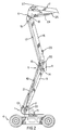
- Figs. 1 and 2 illustrate the aerial work platform according to the present invention in a retracted and extended state, respectively.
- the aerial work platform includes a superstructure support frame 1, having vertically extending plates 2 upon which counterweights, not shown, are adapted to be mounted.
- the support frame is mounted on a turntable 3 carried by a vehicle chassis 4.
- An articulated parallelogram boom assembly 5 is operatively connected between the support frame 1 and a riser 6 connected to the proximate end portion of telescopic boom assembly 7 having a work platform 8 mounted on the distal end thereof.
- the articulated parallelogram boom assembly 5 includes a lower boom assembly having pairs of parallel, laterally spaced compression and tension arms 9 and 10, respectively, extending between the support frame 1 and a floating frame 11.
- the compression and tension arms 9 and 10 are pivotally connected to the support frame as at 12 and 13, and to the floating frame as at 14 and 15.
- the articulated parallelogram boom assembly 5 also includes an upper boom assembly having pairs of parallel, laterally spaced compression and tension arms 16 and 17, respectively, extending between the riser 6 and the floating frame 11.
- the compression and tension arms 16 and 17 are pivotally connected to the riser as at 18 and 19, and to the floating frame 11, as at 20 and 15.
- An extensible hydraulic cylinder 21, positioned on the centerline of the machine, is pivotally connected as at 22 to and between the lower compression arms 9, and as at 23 to and between the upper compression arms 16; whereby, when the cylinder 21 is retracted, the parallelogram assembly 5 is in the folded position, as shown in FIG. 1, and is in the elevated position, as shown in FIG. 2, when the hydraulic cylinder 21 is extended.
- a boom lift cylinder 24 is similarly pivotally connected along the centerline of the machine, above the cylinder 21, between the riser 6, as at 25, and the telescopic boom assembly 7, as at 26.
- the remaining components on the telescopic boom assembly 7 include a master hydraulic cylinder 27 for controlling a slave cylinder 28 on the distal end of the telescopic boom assembly 7 for maintaining the work platform 8 in a horizontal position during the raising and lowering of the parallelogram assembly 5 and the luffing of the telescopic boom assembly 7 with boom lift cylinder 24.
- the cylinder 21 is nested between the pairs of arms 9, 10, 17, and 16; the boom lift cylinder 24 is nested between arms 16 above the cylinder 21; and the master hydraulic cylinder 27 as well as the cylinder inside the telescopic boom assembly 7, for extending and retracting the same, are positioned above the other cylinders on the centerline of the machine.
- Fig. 3 illustrates a top down view of the vehicle chassis 4 for the aerial work platform according to the present invention.
- a first tray 50 connected by hooks 52 in a cantilever fashion to the vehicle chassis 4, supports a battery pack 54.
- the battery pack 54 includes a plurality of batteries connected in series to produce a predetermined voltage. A portion of each member forming the hooks 52 bends away from the first tray 50 to form ears 56.
- Fig. 4 shows a perspective view of the first tray 50.
- the first tray 50 has a bottom 57 with side walls 58 extending therefrom.
- Each side wall 58 has a hook 52 fixed thereto. A portion of the member forming each hook 52 bends away from the side wall 58 to form an ear 56.
- the ears 56 facilitate hooking the first tray 50 on the vehicle chassis 4. For instance, cables can be hooked onto the ears 56, and the first tray 50 with the battery pack 54 thereon lifted by means of the cables to hook the first tray 50 on the vehicle chassis 4 by inserting hooks 52 into slots 53 in the side of chassis 4 (Fig. 1).
- a second tray 60 identical in structure to first tray 50, is connected by hooks 52 in a cantilever fashion to slots 53 in the opposite side of vehicle chassis 4.
- the second tray 60 supports an auxiliary power plant 64 which includes a voltage regulator 66 connected to a power plant 68. As shown, the voltage regulator 66 is connected to the battery pack 54.
- a motor controller 70 is also connected to the battery pack 54 and, in addition, is connected to an electric motor 72.
- the electric motor 72 drives the rear wheels of the aerial work platform.
- the battery pack 54 powers the hydraulic control system (not shown) of the aerial work platform.
- the motor controller 70 regulates the voltage output by the battery pack 54 in accordance with user input received via, for instance, a throttle, and supplies the regulated voltage to the electric motor 72. Because the first tray 50 is removably attachable to the vehicle chassis 4 via hooks 52, the battery pack 54 can be readily hooked and unhooked from the vehicle chassis 4. After hooking the first tray 50 on the vehicle chassis 4, the battery pack 54 is electrically connected to the motor controller 70 via, for instance, cables. The battery pack 54 can also be connected to the auxiliary power plant 64 via, for instance, cables, if such a power plant is provided for the aerial work platform. It should be understood that, according to the invention, the auxiliary power plant may be selectively provided for the aerial work platform.
- the power plant 68 in the auxiliary power plant may be any type of well-known power plant which generates electric power.
- the power plant 68 is a voltage generator driven by a gasoline or diesel powered combustion engine.
- the power plant 68 is a voltage generator driven by a propane engine.
- the power plant 68 is a Kubota ZB600 diesel engine driving an alternator and generator.
- the voltage generated by the power plant 68 is supplied to the voltage regulator 66.
- the voltage regulator 66 may be any well-known voltage regulator.
- the voltage regulator 66 monitors the voltage or charge on the battery pack 54, and when the charge on the battery pack 54 decreases below a predetermined threshold voltage, the voltage regulator 66 supplies the voltage generated by the power plant 68 to the battery pack 54. More specifically, the voltage regulator 66 controls the amount of current flowing to the battery pack 54 based on the difference between the charge on the battery pack 54 and the predetermined threshold voltage.
- the voltage supplied by the voltage regulator 66 includes fluctuations unwanted in a power supply for an electric motor. However, because the voltage output from the voltage regulator 66 charges the battery pack 54, as opposed to serving as a direct power supply for the electric motor 72, the battery pack 54 operates as a filter to remove such fluctuations.
- the auxiliary power plant 64 can be readily hooked and unhooked from the vehicle chassis 4.
- the voltage regulator 66 is electrically connected to the battery pack 54 via, for instance, cables.
- the second tray 60 with the auxiliary power plant 64 thereon can be hooked onto the vehicle chassis 4, and then placed in operation so as to maintain the battery pack 54 charged and operational.
- the auxiliary power plant 64 is also useful when the aerial work platform must be used for an extended period at a location where electric power is not available for recharging the battery pack 54.
- the second tray 60 is easily removed from the vehicle chassis 4, by unhooking the second tray 60 therefrom. Accordingly, the aerial work platform according to the present invention is extremely versatile.
- the battery pack 54 can easily be replaced or exchanged because the first tray 50 supporting the battery pack 54 is also removably attachable to the vehicle chassis 4.
Landscapes
- Engineering & Computer Science (AREA)
- Structural Engineering (AREA)
- Life Sciences & Earth Sciences (AREA)
- Geology (AREA)
- Mechanical Engineering (AREA)
- Forklifts And Lifting Vehicles (AREA)
- Harvesting Machines For Specific Crops (AREA)
Claims (8)
- Arbeitshebebühne mit:gekennzeichnet durch:einem Trägerrahmen (1, 4);Rädern, die drehbar an dem Trägerrahmen (1, 4) angebracht sind;einem Elektromotor (72), der drehbar mindestens eines der Räder antreibt;einem Ausleger (5) mit einem ersten Ende, das gelenkig an dem Trägerrahmen (1, 4) montiert ist;einem Fluidmotor (21), der den Ausleger (5) bezüglich des Trägerrahmens (1, 4) hebt und senkt;einer Arbeitsbühne (8), die durch ein zweites Ende des Auslegers (5) gehalten wird; undeinem Batteriepack (54), welcher den Elektromotor (72) mit Energie versorgt;eine erste Antriebsaggregat-Trägerstruktur (60) zum Tragen eines Zusatz-Antriebsaggregates, welches die Energie ergänzt, die durch den Batteriepack (54) bereitgestellt wird, wobei die erste Trägerstruktur (60) abnehmbar an dem Trägerrahmen (1, 4) angebracht ist.
- Arbeitshebebühne nach Anspruch 1, bei der der Batteriepack (54) die elektrische Energieabgabe durch das Zusatz-Antriebsaggregat filtert.
- Arbeitshebebühne nach Anspruch 1, bei der die erste Trägerstruktur (60) eine Kragarm-Trägerstruktur ist, welche abnehmbar an dem Trägerrahen (1, 4) in auskragender Weise angebracht ist.
- Arbeitshebebühne nach Anspruch 3, bei der die erste Trägerstruktur (60) umfasst:eine Wanne (60); undHaken, die an der Wanne (60) angebracht sind.
- Arbeitshebebühne nach Anspruch 4, bei der die erste Trägerstruktur (60) ferner umfasst:ein Paar hervorstehender Bauteile (56), die von der Wanne (60) hervorstehen.
- Arbeitshebebühne nach Anspruch 1, die femer umfasst:eine zweite Trägerstruktur (50), welche den Batteriepack (54) trägt, wobei die zweite Trägerstruktur (50) abnehmbar an dem Trägerrahmen (1, 4) so angebracht ist, dass der Batteriepack (54) abnehmbar an der Arbeitshebebühne angebracht ist.
- Arbeitshebebühne nach Anspruch 6, bei der die zweite Trägerstruktur (50) eine Kragarm-Trägerstruktur ist, welche abnehmbar an dem Trägerrahmen (1, 4) in auskragender Weise angebracht ist.
- Arbeitshebebühne nach Anspruch 1, bei der die erste Trägerstruktur (60) zum Tragen eines Zusatz-Verbrennungs-Antriebsaggregats dient.
Applications Claiming Priority (2)
| Application Number | Priority Date | Filing Date | Title |
|---|---|---|---|
| US08/957,798 US6012544A (en) | 1997-10-24 | 1997-10-24 | Aerial work platform with removably attachable support structure for auxiliary power plant |
| US957798 | 1997-10-24 |
Publications (3)
| Publication Number | Publication Date |
|---|---|
| EP0921094A2 EP0921094A2 (de) | 1999-06-09 |
| EP0921094A3 EP0921094A3 (de) | 2000-12-20 |
| EP0921094B1 true EP0921094B1 (de) | 2005-03-30 |
Family
ID=25500154
Family Applications (1)
| Application Number | Title | Priority Date | Filing Date |
|---|---|---|---|
| EP98119731A Expired - Lifetime EP0921094B1 (de) | 1997-10-24 | 1998-10-20 | Arbeitshebebühne mit abnehmbarem Tragkonstruktion für eine Hilfskraftanlage |
Country Status (6)
| Country | Link |
|---|---|
| US (1) | US6012544A (de) |
| EP (1) | EP0921094B1 (de) |
| JP (1) | JPH11217194A (de) |
| AU (1) | AU751548B2 (de) |
| CA (1) | CA2251302C (de) |
| DE (1) | DE69829541D1 (de) |
Cited By (1)
| Publication number | Priority date | Publication date | Assignee | Title |
|---|---|---|---|---|
| EP2368829A1 (de) | 2010-03-24 | 2011-09-28 | Hermann Paus Maschinenfabrik GmbH | Mobiles Arbeitsgerät in Form eines Schrägaufzuges |
Families Citing this family (22)
| Publication number | Priority date | Publication date | Assignee | Title |
|---|---|---|---|---|
| DE19948831B4 (de) * | 1999-10-06 | 2005-06-30 | Terex-Demag Gmbh & Co. Kg | Fahrzeugkran |
| NL1020371C2 (nl) * | 2002-04-11 | 2003-10-14 | Skf Ab | Elektrisch aangedreven vorkheftruck. |
| US6810993B2 (en) * | 2002-07-29 | 2004-11-02 | Terex-Telelect, Inc. | Articulated aerial device including an upper boom compensation unit |
| ITMI20040092A1 (it) * | 2004-01-23 | 2004-04-23 | Cte S P A | Veicolo elevatore |
| US20080251593A1 (en) * | 2007-04-12 | 2008-10-16 | Brandt Richard F | Natural or propane gas feed auxiliary electric generating system for boilers or furnaces |
| IT1395446B1 (it) * | 2009-07-22 | 2012-09-21 | Hinowa S P A | Piattaforma aerea |
| CN102351138A (zh) * | 2011-09-22 | 2012-02-15 | 北京三兴汽车有限公司 | 简易式车载举升装置 |
| US11305972B1 (en) * | 2011-11-11 | 2022-04-19 | Vehcile Service Group, Llc | Vehicle lift with locally stored energy source |
| NL2011596C2 (nl) | 2013-10-11 | 2015-04-14 | Hudson Bay Holding B V | Elektrische aandrijving van mobiele inrichting. |
| US8979467B1 (en) * | 2013-10-16 | 2015-03-17 | Jeffrey H. Bailey | Crane having a toolless removable battery and progressive function control |
| US9120651B1 (en) * | 2013-10-16 | 2015-09-01 | Jeffrey H. Bailey | Crane having a toolless removable battery and progressive function control |
| ITUB20155900A1 (it) * | 2015-11-25 | 2017-05-25 | Magni Telescopic Handlers S R L | Piattaforma aerea semovente |
| IT201600106155A1 (it) * | 2016-10-21 | 2018-04-21 | Magni Telescopic Handlers S R L | Quadro comandi per macchina operatrice |
| FR3102472B1 (fr) | 2019-10-25 | 2022-03-11 | Haulotte Group | Nacelle elevatrice dotee d’un emplacement pour un groupe electrogene amovible |
| CA3128026C (fr) | 2019-01-29 | 2026-03-03 | Haulotte Group | Nacelle elevatrice apte a une utilisation en interieur et en exterieur tout terrain |
| FR3092101B1 (fr) * | 2019-01-29 | 2021-10-29 | Haulotte Group | Nacelle elevatrice apte a une utilisation tout terrain en exterieur |
| US12036888B2 (en) | 2020-03-06 | 2024-07-16 | Oshkosh Corporation | Battery monitoring system for a lift device |
| AU2021232056A1 (en) * | 2020-03-06 | 2022-10-13 | Oshkosh Corporation | Lift device innovations |
| FR3113047B1 (fr) | 2020-07-30 | 2022-10-21 | Haulotte Group | Dispositif amovible verrouillable dans un emplacement dédié d’un engin |
| CA3222062A1 (fr) * | 2021-07-21 | 2023-01-26 | Olivier GUILLERMIN | Engin de levage automoteur ayant une source d'energie electrique principale et pouvant recevoir differentes sources d'energie electrique secondaires interchangeables |
| FR3125520B1 (fr) * | 2021-07-21 | 2023-12-22 | Haulotte Group | Engin de levage automoteur ayant une source d’énergie électrique principale et pouvant recevoir différentes sources d’énergies électriques secondaires interchangeables |
| HUE070766T2 (hu) * | 2021-07-21 | 2025-07-28 | Manitou Italia Srl | Teleszkópos rakodó átalakítható hajtással |
Family Cites Families (10)
| Publication number | Priority date | Publication date | Assignee | Title |
|---|---|---|---|---|
| US1734645A (en) * | 1928-04-16 | 1929-11-05 | Bruno A Polland | Battery-box holddown |
| US3667563A (en) * | 1969-11-21 | 1972-06-06 | Allis Chalmers Mfg Co | Supporting structure for platform defining fuel and battery compartment |
| JPS4930648B1 (de) * | 1969-12-12 | 1974-08-15 | ||
| DE2522844C3 (de) * | 1975-05-23 | 1979-01-11 | Bayerische Motoren Werke Ag, 8000 Muenchen | Elektrisch angetriebenes Fahrzeug, insbesondere Personenkraftwagen |
| US4019604A (en) * | 1975-06-16 | 1977-04-26 | Fabtek, Inc. | Elevating platform apparatus |
| US4593779A (en) * | 1982-12-21 | 1986-06-10 | Still Gmbh | Combination internal combustion and electrical drive vehicles |
| US5251721A (en) * | 1992-04-21 | 1993-10-12 | Richard Ortenheim | Semi-hybrid electric automobile |
| DE69427248T2 (de) * | 1993-04-01 | 2001-09-13 | Gnb Industrial Battery Co., Lombard | Tablettanordnung von gasdichte Bleisäurezellen und Kraftfahrzeug mit Verwendung solcher Tablettanordnung von Zellen |
| US5584356A (en) * | 1995-05-31 | 1996-12-17 | Kidde Industries, Inc. | Centerline double riser with single lift cylinder and link for a low profile self propelled aerial work platform |
| US6065565A (en) * | 1997-01-30 | 2000-05-23 | Jlg Industries, Inc. | Hybrid power system for a vehicle |
-
1997
- 1997-10-24 US US08/957,798 patent/US6012544A/en not_active Expired - Lifetime
-
1998
- 1998-10-19 CA CA002251302A patent/CA2251302C/en not_active Expired - Lifetime
- 1998-10-20 EP EP98119731A patent/EP0921094B1/de not_active Expired - Lifetime
- 1998-10-20 DE DE69829541T patent/DE69829541D1/de not_active Expired - Lifetime
- 1998-10-22 AU AU89476/98A patent/AU751548B2/en not_active Expired
- 1998-10-23 JP JP10302123A patent/JPH11217194A/ja active Pending
Cited By (2)
| Publication number | Priority date | Publication date | Assignee | Title |
|---|---|---|---|---|
| EP2368829A1 (de) | 2010-03-24 | 2011-09-28 | Hermann Paus Maschinenfabrik GmbH | Mobiles Arbeitsgerät in Form eines Schrägaufzuges |
| DE102010012469A1 (de) | 2010-03-24 | 2011-09-29 | Hermann Paus Maschinenfabrik Gmbh | Mobiles Arbeitsgerät in Form eines Schrägaufzuges |
Also Published As
| Publication number | Publication date |
|---|---|
| EP0921094A2 (de) | 1999-06-09 |
| EP0921094A3 (de) | 2000-12-20 |
| JPH11217194A (ja) | 1999-08-10 |
| AU751548B2 (en) | 2002-08-22 |
| AU8947698A (en) | 1999-05-13 |
| CA2251302C (en) | 2005-01-04 |
| US6012544A (en) | 2000-01-11 |
| DE69829541D1 (de) | 2005-05-04 |
| CA2251302A1 (en) | 1999-04-24 |
Similar Documents
| Publication | Publication Date | Title |
|---|---|---|
| EP0921094B1 (de) | Arbeitshebebühne mit abnehmbarem Tragkonstruktion für eine Hilfskraftanlage | |
| US7667341B2 (en) | Power-generating apparatus, such as a generator | |
| JP3859982B2 (ja) | ハイブリッド建設機械の電力制御装置 | |
| CN113710606B (zh) | 适于室内和全地形户外使用的高空作业平台 | |
| US20010052433A1 (en) | Hybrid power supply module | |
| US20240317558A1 (en) | Self-propelling piece of lifting machinery having a main electrical power source and able to accommodate various interchangeable secondary electrical power sources | |
| US12297090B2 (en) | Rotary telescopic boom lift | |
| KR20210122685A (ko) | 이동식 작업기계 | |
| JP2007071197A (ja) | ハイブリッド型油圧作業機 | |
| CN110915092A (zh) | 供电设备以及履带式车辆 | |
| CN114873487A (zh) | 具有电力驱动装置的移动式起重机 | |
| CN118205441A (zh) | 一种侧向换电方法及装置 | |
| CN118176128A (zh) | 作业车辆 | |
| US20250376040A1 (en) | Boom construction for dynamic energy transfer system | |
| JP3801511B2 (ja) | 電気駆動型作業車 | |
| MXPA98008859A (en) | Aerial work platform with a support structure that can be joined removibly for a plant of auxiliary energy | |
| JP2006136119A (ja) | 作業用車両の充電装置 | |
| JP2002262407A (ja) | 工事用電気車 | |
| JPS604687B2 (ja) | 連成刈取機 | |
| JPH1080006A (ja) | 電気自動車のバッテリー充電用キャリアカー | |
| JP2025110722A (ja) | 車載バッテリ充電システム | |
| JP2568837Y2 (ja) | 高所作業車の電源供給装置 | |
| CN117730048A (zh) | 具有主电源,并能容纳各种可替换辅助电源的自动式起重机 | |
| JP2025110723A (ja) | 車載バッテリ充電システム | |
| JP5851754B2 (ja) | 作業車両 |
Legal Events
| Date | Code | Title | Description |
|---|---|---|---|
| PUAI | Public reference made under article 153(3) epc to a published international application that has entered the european phase |
Free format text: ORIGINAL CODE: 0009012 |
|
| AK | Designated contracting states |
Kind code of ref document: A2 Designated state(s): DE FI FR IT NL SE |
|
| AX | Request for extension of the european patent |
Free format text: AL;LT;LV;MK;RO;SI |
|
| PUAL | Search report despatched |
Free format text: ORIGINAL CODE: 0009013 |
|
| AK | Designated contracting states |
Kind code of ref document: A3 Designated state(s): AT BE CH CY DE DK ES FI FR GB GR IE IT LI LU MC NL PT SE |
|
| AX | Request for extension of the european patent |
Free format text: AL;LT;LV;MK;RO;SI |
|
| RIC1 | Information provided on ipc code assigned before grant |
Free format text: 7B 66F 11/04 A, 7B 60K 6/04 B |
|
| 17P | Request for examination filed |
Effective date: 20010522 |
|
| AKX | Designation fees paid |
Free format text: DE FI FR IT NL SE |
|
| 17Q | First examination report despatched |
Effective date: 20031020 |
|
| GRAP | Despatch of communication of intention to grant a patent |
Free format text: ORIGINAL CODE: EPIDOSNIGR1 |
|
| GRAS | Grant fee paid |
Free format text: ORIGINAL CODE: EPIDOSNIGR3 |
|
| GRAA | (expected) grant |
Free format text: ORIGINAL CODE: 0009210 |
|
| AK | Designated contracting states |
Kind code of ref document: B1 Designated state(s): DE FI FR IT NL SE |
|
| PG25 | Lapsed in a contracting state [announced via postgrant information from national office to epo] |
Ref country code: NL Free format text: LAPSE BECAUSE OF FAILURE TO SUBMIT A TRANSLATION OF THE DESCRIPTION OR TO PAY THE FEE WITHIN THE PRESCRIBED TIME-LIMIT Effective date: 20050330 Ref country code: FI Free format text: LAPSE BECAUSE OF FAILURE TO SUBMIT A TRANSLATION OF THE DESCRIPTION OR TO PAY THE FEE WITHIN THE PRESCRIBED TIME-LIMIT Effective date: 20050330 |
|
| REF | Corresponds to: |
Ref document number: 69829541 Country of ref document: DE Date of ref document: 20050504 Kind code of ref document: P |
|
| RAP2 | Party data changed (patent owner data changed or rights of a patent transferred) |
Owner name: JLG INDUSTRIES, INC. |
|
| PG25 | Lapsed in a contracting state [announced via postgrant information from national office to epo] |
Ref country code: DE Free format text: LAPSE BECAUSE OF FAILURE TO SUBMIT A TRANSLATION OF THE DESCRIPTION OR TO PAY THE FEE WITHIN THE PRESCRIBED TIME-LIMIT Effective date: 20050701 |
|
| NLT2 | Nl: modifications (of names), taken from the european patent patent bulletin |
Owner name: JLG INDUSTRIES, INC. |
|
| NLV1 | Nl: lapsed or annulled due to failure to fulfill the requirements of art. 29p and 29m of the patents act | ||
| PLBE | No opposition filed within time limit |
Free format text: ORIGINAL CODE: 0009261 |
|
| STAA | Information on the status of an ep patent application or granted ep patent |
Free format text: STATUS: NO OPPOSITION FILED WITHIN TIME LIMIT |
|
| ET | Fr: translation filed | ||
| 26N | No opposition filed |
Effective date: 20060102 |
|
| PG25 | Lapsed in a contracting state [announced via postgrant information from national office to epo] |
Ref country code: SE Free format text: LAPSE BECAUSE OF FAILURE TO SUBMIT A TRANSLATION OF THE DESCRIPTION OR TO PAY THE FEE WITHIN THE PRESCRIBED TIME-LIMIT Effective date: 20050630 |
|
| REG | Reference to a national code |
Ref country code: FR Ref legal event code: PLFP Year of fee payment: 18 |
|
| REG | Reference to a national code |
Ref country code: FR Ref legal event code: PLFP Year of fee payment: 19 |
|
| REG | Reference to a national code |
Ref country code: FR Ref legal event code: PLFP Year of fee payment: 20 |
|
| PGFP | Annual fee paid to national office [announced via postgrant information from national office to epo] |
Ref country code: FR Payment date: 20171024 Year of fee payment: 20 |
|
| PGFP | Annual fee paid to national office [announced via postgrant information from national office to epo] |
Ref country code: IT Payment date: 20171023 Year of fee payment: 20 |