EP0921463B1 - Verfahren und Gerät zur Steuerung von nicht immanenten Rechner-Systemeinrichtungen mittels graphischen Oberfläche - Google Patents
Verfahren und Gerät zur Steuerung von nicht immanenten Rechner-Systemeinrichtungen mittels graphischen Oberfläche Download PDFInfo
- Publication number
- EP0921463B1 EP0921463B1 EP99104745A EP99104745A EP0921463B1 EP 0921463 B1 EP0921463 B1 EP 0921463B1 EP 99104745 A EP99104745 A EP 99104745A EP 99104745 A EP99104745 A EP 99104745A EP 0921463 B1 EP0921463 B1 EP 0921463B1
- Authority
- EP
- European Patent Office
- Prior art keywords
- control
- master
- graphical
- computer
- user
- Prior art date
- Legal status (The legal status is an assumption and is not a legal conclusion. Google has not performed a legal analysis and makes no representation as to the accuracy of the status listed.)
- Expired - Lifetime
Links
Images


Classifications
-
- G—PHYSICS
- G06—COMPUTING OR CALCULATING; COUNTING
- G06F—ELECTRIC DIGITAL DATA PROCESSING
- G06F8/00—Arrangements for software engineering
- G06F8/30—Creation or generation of source code
- G06F8/34—Graphical or visual programming
Definitions
- application programs are typically represented to a user by an icon displayed within a window on a computer screen, one icon for each application program that can be run. Execution of an application program is initiated by selecting its corresponding icon, most often using a pointing device such as a mouse.
- a message is sent to the corresponding application program object, indicating that the application program object is to invoke certain of its methods. For example, if a word processing program is selected, the methods contained within the application program object may include starting the word processing program.
- the user may also "drag" icons from one area of the screen to another, or from one window to another using the mouse.
- the user may even "drag" one icon representative of an application object and "drop” that icon on top of another.
- This "object-object” interaction will result in a combination of application objects. For example, if a word processing document icon is dropped upon a word processing program icon, the object-object interaction results in starting the word processing program and causing that program to open the word processing document. This is possible because both the word processing program and the word processing document have been represented as compatible application program objects.
- the icons in the object-oriented programming paradigm allow the user to graphically control various computer system elements and the interrelationships between computer system elements.
- Non-computer system devices include virtually any electronic device equipped with the necessary hardware to be connected to a personal computer either directly or via a network.
- non-computer system devices may include lamps, television sets, VCRs, video cameras, telephones, amplifiers, CD players, equalizers, etc.
- Such devices typically come equipped with a variety of feature controls and displays for operation including volume controls, power switches, input and output meters, channel selectors, etc.
- each feature control e.g., a volume control
- feature display e.g., an output meter
- non-computer system devices have been graphically represented and controlled via a special program designed specifically for each device, where the specially designed program is either built into the computer operating system or loaded into the computer operating system as an add-on software product.
- the CD Remote program, Version 1.3 for the Macintosh computer provides the computer user with a graphic interface for controlling a Macintosh CD player hardwired to the computer.
- the user is provided with a graphical display of the CD players control panel, complete with graphical stop, play, pause, skip, etc. controls. To initiate execution of any one of these commands upon the CD player, the user merely selects the corresponding graphical control using the mouse.
- the graphical controls are not visible screen entities that the user can "drag and drop” or “cut and paste” into other areas of the screen, into other windows, or on top of one another. Instead, the placement, position and execution of each of the graphical controls is predefined by the specially designed CD Remote program for the CD player.
- US 4849880 discloses a system for programming a computer which provides a set of software-based virtual machines each for instructing a computer to carry out a selected operation. Each virtual machine is represented by a virtual front panel displayed on a screen and each virtual front panel graphically displays operator controllable values of input and output parameters utilized by the virtual machine it represents.
- the system is adapted to sythesize a new virtual machine for instructing the computer to perform a sequence of operations wherein each operation is carried out by the computer according to the instructions of an operator selected one of the existing virtual machines.
- the system also creates a new virtual front panel for displaying input and output parameters associated with the new virtual machine.
- the system permits the operator to program the computer by directing synthesis of a hierarchy of virtual machines.
- an operator wishes to sythesize a new virtual machine, it is said that he should create new instances for every existing virtual instrument (machine) needed to perform the sequence of operations represented by the new virtual instrument.
- the operator To create a new virtual instrument, the operator must first create a new class and then define the functions that new class is to perform in terms of the functions the existing virtual machines perform.
- the end product of the synthesizing process is a Smalltalk listing.
- EP-A-596594 discloses a control device method and apparatus having application for use in multi-media systems.
- the multi-media system contains a host computer having a video display, a control device and at least one target device.
- the target device is any remotely controlled equipment that the user wishes to integrate into the multi-media system.
- the host computer contains a host system configuration which provides the user the ability to select an operating mode for the control device.
- the control device operates as an interactive user interface to control a cursor on the host computer video display when the control device is placed in the cursor control mode.
- Non-computer system devices are devices that can be electronically controlled such as musical amplifiers and equalizers, television sets, VCRs, video cameras, etc.
- the graphical control system includes a computer, an interface(s) for a non-computer system device(s) having at least one feature control, a coupling medium for coupling the computer to the interface(s) and a visual network operating system (VNOS).
- VNOS visual network operating system
- the visual network operating system is a distributed operating system that is partially stored in a computer and partially stored in the interface(s).
- the major portion is stored in the computer.
- the computer portion causes the computer to generate or create graphical controls that represent the type of feature controls normally associated with the non-computer system devices connected to the network.
- Such controls may include an on/off switch, an input meter and a volume control.
- An equalizer would include boost and cut controls for frequency bands.
- the graphical controls are operated by a conventional graphical control device, such as a mouse, track ball, touch screen, joystick, etc. As the graphical controls are operated, the computer sends messages to the interface(s), which cause the non-computer system devices to respond in the same way the devices would have responded to the manual or electrical operation of the equivalent feature controls.
- VNOS visual network operating system
- object-oriented programming paradigm in which objects are interoperable and are organized into classes in a hierarchical fashion.
- window objects contain the data and methods necessary for displaying a window on the screen of the computer display.
- Visual reference objects contain the methods and data necessary for displaying and associating icons and visual device controls (VDCs) with a window object.
- VDCs visual device controls
- a VCE object contains a value represented by the VDC and controlled by setting the VDC, and methods for manipulating the value.
- a device object contains the methods and data for communicating with particular types of non-computer system devices and for managing a graphical representation of a non-computer system device.
- Packet objects contain the methods and data for communicating data between the computer and non-computer system devices via the network.
- the invention provides a graphical control system for controlling a wide variety of non-computer system devices.
- Virtually any electronic device equipped with the necessary hardware can be controlled.
- the graphical control system creates visual device controls that represent the feature controls and feature displays normally associated with the non-computer system device that is to be controlled.
- The-visual device controls are operated by a conventional user manipulation device, such as a mouse, track ball, touch screen, joystick, etc.
- the invention eliminates the need for specially designed code for each non-computer system device by employing an object-oriented paradigm to represent the non-computer system devices.
- the present invention is directed to a graphical control system for controlling non-computer system devices, wherein virtually any electronically controllable device equipped with the necessary interface hardware can be controlled. While the following description explains the invention in connection with musical system components, such as amplifiers and equalizers, it is to be understood that the invention can be used with other non-computer system devices, including a simple on/off switch for controlling a lamp. In addition, the invention easily accommodates non-computer system devices produced by various manufacturers.
- the invention employs a personal computer, a network, interfaces for connecting the computer and the non-computer system devices to the network, and a visual network operating system.
- FIGURE 1 illustrates a bus network 28 interconnecting a personal computer 20 and a plurality of non-computer system devices 21.
- the graphical control system of the present invention employing the object-oriented programming paradigm as described above allows a user to use the personal computer 20 to control the operation of the non-computer system devices 21 via bus network 28.
- the illustrated devices are a two-channel amplifier 22, a tuner 24 and a graphic equalizer 26.
- additional non-computer system devices can be connected to and controlled by personal computer 20 via the bus network 28, if equipped with the necessary interface hardware.
- Non-computer system devices may include video cameras, speakers, television sets, telephones, lamps, etc. Even simple light switches can form non-computer system devices.
- the devices shown in FIGURE 1 are depicted as audio sound system devices, i.e., amplifiers, equalizers, tuners, etc.
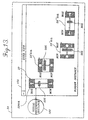
- the personal computer 20 is connected to the network 28 by way of an RS232 interface 42 and a bridge 45.
- Standard personal computers typically include an RS232 card 43 and an RS232 cable 44 for communicating with external devices such as printers.
- RS232 is an interface standard that specifies signal voltage levels, etc.
- RS232 is also a byte-level communication protocol that specifies start bits, stop bits, etc. for sending bytes of data.
- a higher level communication protocol is used on top of the RS232 byte-level communication protocol, i.e., the personal computer 20 includes software defining a point-to-point communication protocol that is used on top of the RS232 byte-level protocol.
- the bridge 45 provides the interface between the RS232 cables 38 and the bus network 28, on which a network communication protocol is used.
- the bus network 28 shown in FIGURES 1 and 2 can be formed of various coupling media such as glass or plastic fiber optic cables, coaxial cables, twisted wire pair cables, ribbon cables, etc. In the professional audio industry it is generally preferable to use fiber optic cables, as fiber optic cables are highly immune to electromagnetic interference and are capable of carrying signals over long distances without significant attenuation As described herein, the bus network 28 represents fiber optic cables. Accordingly, the I/O board 47 of interface 35 shown in FIGURE 2 is constructed for use with fiber optic cables.
- the network communication protocol used to communicate over the bus network 28 is of the type disclosed in commonly assigned U.S. Patent No. 5,245,604, entitled “Communication System,” the disclosure and drawings of which are specifically incorporated herein by reference.
- the network communication protocol described by U.S. Patent No. 5,245,604 is referred to herein as the MediaLink protocol.
- the advantage of the MediaLink protocol is that it provides an upper limit on the amount of time it takes to communicate over the bus network 28. This is important in real-time environments such as a musical performance stage, where unpredictable delay would result in unacceptable distortion.
- the MediaLink protocol includes a network resource sharing and management algorithm such that only one device communicates over the bus network 28 at any one given time and such that each device has sufficient access to the bus network 28. While the MediaLink protocol and the bus network are presently preferred, it is to be understood that other network protocols and networks other than the type shown in FIGURES 1 and 2 may be used in actual embodiments of the invention, if desired.
- a non-computer system device 21 may be connected to personal computer 20 in a point-to-point configuration by way of a cable so that a bridge 45 is unnecessary.
- the device would include the interface 35 having processor board 46 and I/O board 47.
- the I/O board 47 would be specifically constructed for use with the point-to-point configuration and a particular type of transmission medium. Network and access management would obviously be unnecessary since the personal computer and the device are interconnected in a point-to-point configuration.
- the device is connected to the personal computer 20 by a RS232 cable.
- the coupling medium could also include a radio frequency coupling medium or other coupling media.
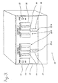
- a non-computer system device 21 connected to the personal computer 20 via the network 28 (FIGURE 1) is shown in more detail in FIGURE 3.
- the chosen non-computer system device 21 is the two-channel amplifier 22, which has a control and display panel 48 that contains a number of feature controls 29a, including a first fader 49, a second fader 50, a first power switch 51, a second power switch 52; and feature displays 29b, including a first input meter 53, a first output meter 54, a second input meter 55, and a second output meter 56.
- One of the faders, power switches and input and output meters is associated with each of the channels
- the feature controls and displays shown in FIGURE 3 should be construed as exemplary and not limiting.
- Other types of amplifiers could include various controls and displays (such as mute controls, fuse temperature gauges, etc.) other than or in addition to those shown in FIGURE 3.
- devices other than amplifiers include other types of controls and displays, depending upon the nature of each device.
- the amplifier 22 shown in FIGURE 3 is equipped with the hardware described above necessary to connect the amplifier 22 to the personal computer 20 via the network 28 so that data packets may be sent between the amplifier 22 and the personal computer 20. More specifically, the amplifier 22 is equipped with a processor board 46 and an I/O board 47. With respect to the processor board 46, the processor 41 preferably includes read-only memory (ROM) that stores program code for controlling the communication of the device with the personal computer 20 and with other devices.
- the EEPROM 58 is used by the processor 41 for controlling the functionality of the amplifier 22 and stores a portion of the visual network operating system.
- the RAM 59 is used by the processor 41 during operation to temporarily store some program code and data, including a class database containing instances of each class employed by the portion of the visual network operating system stored in the EEPROM.
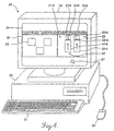
- the personal computer 20 included in FIGURES 1 and 2 is shown in more detail in FIGURE 4.
- the personal computer 20 includes a display or monitor 30, a keyboard 31, a mouse 32, and a main unit 33.
- the monitor 30 includes a screen 34 on which various elements of a graphical control system formed in accordance with this invention are displayed.
- the displayed elements include windows 36 and 38, and graphics cursor 37.
- One of the illustrated windows 36 is named “Network Inventory” and the other illustrated window 38 is named "Amplifier Panel.”
- the Network Inventory window 36 contains three icons 39, each of which represents one of the non-computer devices 21 connected to the bus network 28.
- the graphical control system produces the Amplifier Panel window 38 on the screen 34 of the personal computer 20.
- FIGURE 6 shows the Amplifier Panel window in much greater detail.
- the Amplifier Panel window 38 is a predefined graphical control display of the control panel 48 of the amplifier 22 shown in FIGURE 3. Consequently, the Amplifier Panel window 38 contains a VDC 40 for each feature control 29a or feature display 29b of the amplifier 22.
- VDCs 49a, 50a and 53a graphically represent the first fader 49, the second fader 50 and the first input meter 53 of the amplifier 22 shown in FIGURE 3, respectively.
- the second input meter 55 is graphically represented by another VDC 55a
- the first and second output meters 54 and 56 are graphically represented by still other VDCs 54a and 56a, respectively.
- still other VDCs 51a and 52a represent the first and second power switches 51 and 52, respectively.
- the first fader 49 also may be effectuated manually, electrically or by control of another personal computer connected to the bus network 28. For example, if the Channel 1 volume of the amplifier 22 is increased by manually operating the first fader 49, a change in the value represented by the first fader results.
- the graphical control system communicates the change in value to the personal computer 20 so that the visual device control element or knob 301 of the first fader VDC 49a is regenerated in a manner that visually corresponds to the change in value.
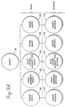
- VNOS 78 uses an object-oriented programming paradigm to represent non-computer system devices 21.
- object-oriented programming paradigms are abstract generic descriptions of objects and their behaviors.
- a class defines a certain category or grouping of methods and data within an object.
- Methods provide the "intelligence" of a class and comprise procedures or codes that operate upon the data.
- Methods as applied to data define the behavior of an object.
- This concentration of intelligence in the methods of object classes is essential in object-oriented systems. It permits large-scale maintenance efforts, since the methods or intelligence of objects is inherited from their class. So, effecting a change once in the methods of a class will automatically effect changes in the methods of all the objects of that class and its subclasses.
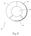
- Generic methods 96 and 98 around the outer part of the doughnut are generic methods present in all objects of a class.
- Generic methods 96 are generally those used to translate the data 92 into a linear, textual representation so that the data can be directed to and from a text file in storage 66 of the personal computer 20 by the platform operating services of VNOS 78.
- Generic methods 96 are employed when the user requests a full state save or restoration of all objects upon shut-down or power-up of the personal computer.
- Generic methods 96 are also referred to as "interpret and describe" methods.
- Generic methods 98 provide for communication between objects including methods for generating pointers to other objects and methods for sending messages to other objects.
- class-specific methods 504 contained in a window object 100 provide the graphical appearance of a window as defined by that computer's particular windowing environment, such as the Apple Mac OS or Microsoft Windows.
- class-specific methods 504 provide for the organization of the icons 39 and VDCs 40 within the window object 100.
- the generic methods 508 of a window object provide communication between the remaining four classes of objects.
- the VCE object data 542 includes a list of pointers to related window, visual reference, VCE, device and packet objects and generic methods 546 providing for communication between these objects.
- the VCE object itself does not appear on the computer screen 34.
- class-specific methods 544 which would normally control a VCE object's appearance are not present.
- a packet object 108 contains the methods and data for generically communicating between a device 21 and the computer 20 via the bus network 28.
- the data 582 of a packet object 108 contains a list of pointers to related VCE objects 104 and device objects 106.
- the data 582 of a packet object includes device information to be transmitted over the network in a data packet.
- packet object data 582 contains the value(s) represented by one or more VDCs and stored in one or more VCEs.
- Class-specific methods 584 of a packet object 108 provide for communication between the personal computer 20 and devices 21 via the network 28 over different ports or in conjunction with the MediaLink protocol.
- the preferred embodiment of the graphical control system of the present invention includes a personal computer 20, an interface 35 for each non-computer system device 21 having at least one feature control 29a or display 29b, a bus network 28 for connecting the computer 20 to the interface(s) 35, and a VNOS 78 based on the object-oriented programming paradigm just described.
- Embodiments of this graphical control system can best be understood by describing the presently preferred embodiment of VNOS 78 and the object-oriented programming paradigm in which it exists. Such a description follows.
- FIGURE 11 is used to illustrate how the graphical control system of the invention enables a user to control a device via a graphical representation.
- VNOS 78 generates a window instance 140 on the screen 34 based upon performing a predetermined function when a cursor is positioned over an icon.
- the window instance 140 is simplified by showing only a part of the Amplifier Panel window 36 depicted in FIGURES 4 and 6. Specifically, only the Channel 1 input meter VDC 53a and the first and second fader VDCs 49a and 50a are shown.
- the user can graphically manipulate any of the VDCs by using the mouse 32 to guide the cursor 37 and perform some predefined function, such as clicking a mouse button, all in a conventional manner.
- the class-specific methods 576 of the device instance 166 prepares an outgoing packet instance 178 containing the new value data 592.
- the outgoing packet instance 178 is then transformed into a conventional packet by the platform operating services of VNOS 78 and sent over the network 28 to notify the amplifier 22 of the change in value.
- the amplifier interface 35 Upon receipt, the amplifier interface 35 correspondingly adjusts the volume controlled by first fader 49.
- VNOS 78 at the device interface in adjusting controls, such as the first fader 49, is discussed in more detail below.
- first fader 49 or the second fader 50 of the amplifier 22 are manually or electrically operated, or operated by another computer, the flow of messages illustrated in FIGURE 12 is reversed. More specifically, if first fader 49 of the amplifier 22 is manually operated, VNOS 78 causes the amplifier interface 35 to send a packet to the computer 20 via the bus network 28. When the packet is received, the packet is transformed by the platform operating services provided by VNOS 78 into an incoming packet instance 168. The incoming packet instance 168 sends a message to the device instance 166 notifying it that a change has occurred in the value associated with the first fader 49. Consequently, device instance 166 sends a message to the first fader VCE instance 164.
- the second fader VDC visual reference instance 172 causes the second fader VDC 50a to be regenerated in the Amplifier Panel window instance 140, while the second fader VDC clone visual reference instance 182 causes the second fader VDC clone 50aa to be regenerated VDC 304 in the User View window instance 150.
- the second fader VDC and the second fader VDC clone are simultaneously being regenerated in a way that corresponds to the change in value effectuated by the manual or electrical change made to the second fader 50 of the amplifier.
- FIGURE 13 includes a User View window instance 150 that includes the second fader VDC clone 50aa of the amplifier 22. While for purposes of clarity in illustration, the accompanying VCE, device and packet instances have been omitted from FIGURE 13, it will be appreciated that second fader VDC clone 50aa remains associated with those instances from FIGURE 13, which are depicted in FIGURE 12, through the associated visual reference instance 182. As will be better understood from the following description, it is immaterial for purposes of this aspect of the invention whether the depicted VDC clone 50 is an original or a cloned VDC.
- the second fader VDC clone 50aa shown in FIGURE 13 is a graphical representation of second fader 50 of the amplifier 22.
- the second fader VDC clone 50a appears as a rectangle having a height greater than its width that is operated vertically by moving a graphical knob 305 upwardly toward a maximum (MAX) value or downwardly toward a minimum (MIN) value.
- MAX maximum
- MIN minimum
- the knob is "moved” by appropriately manipulating a mouse or other cursor control device. Movement of the graphical knob changes the value represented by the second fader VDC clone 50aa and, in turn, causes the second fader VDC clone 50aa to be regenerated with the change in value depicted.
- FIGURE 13 also includes three other second fader VDC clones 50'aa, 50"aa, and 50"'aa having different height and width dimensions but otherwise having the same graphics as the second fader VDC clone 50aa.
- the height of the first other second fader VDC clone 50'aa is less and the width greater than the original second fader VDC clone 50aa.
- the height of the second other second fader VDC clone 50"aa is less and the width greater than the first other second fader VDC clone 50'aa.
- the related window instance 150 sends a message to the visual reference instance 182 associated with the second fader VDC clone.
- the class-specific methods 524 of the visual reference instance 182 cause the second fader VDC clone to be automatically regenerated in a form designed for horizontal as opposed to vertical operation.
- the orientation of the second fader VDC clone is rotated by 90°.
- the second and third other second fader VDC clones 50"aa and 50"'aa still graphically represent the second fader 50 of the amplifier 22, they are operated by the graphical knob 305 of the VDC horizontally rather than vertically.
- the automatic reorientation of the second fader VDC clone does not result in a change in value nor does it result in a change of the MAX and MIN values Consequently, no messages are sent to the other VCE, device and packet instances (FIGURE 12).
- the second fader VDC clone may be returned to its original form having its original orientation and dimensions by reversing the foregoing procedure, if desired. It will also be appreciated that any other VDC 40 may be automatically resized and, if desired, reoriented in a similar manner.
- Tool Box window instance 160 may contain a number of "template” VDCs, each of which can be cloned in one or more User View window instances in the manner described above. It will also be appreciated that a template VDC may be "dropped" upon another VDC 40 using the mouse and that the VDC 40 will regenerate itself accordingly.
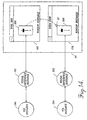
- FIGURE 15 two window instances are shown on screen 34 of the personal computer 20, the User View window instance 170 shown in FIGURE 14 and an Amplifier Panel window instance 180.
- the User View window instance 170 contains the master VDC 308.
- FIGURE 15 also includes the master reference instance 202 and the master VCE instance 204.
- the Amplifier Panel window instance 180 contains a VDC 310 that graphically represents a control 29a, such as a fader, of an amplifier.
- the user using a mouse or other cursor control device to manipulate the cursor 37 drags the amplifier control VDC 310 from the Amplifier Panel window instance 180 into the User View window instance 170 in the manner previously described.
- the amplifier control VDC 310 is moved until it is positioned atop the master VDC where it is trapped by the user releasing a depressed key of the mouse or other cursor control device.
- an object-to-object interaction (as shown by the dotted line and phantom VDC) occurs.
- the object-to-object interaction establishes a master-slave relationship between the amplifier control VDC 310 and the master VDC 308.
- the object-to-object interaction causes the User View window instance 170 to send a message to the master visual reference instance 202, which in turn sends a message to the master VCE instance 204.
- the class-specific methods 554 of the master VCE instance 204 establish a link to a VCE instance 214 associated with the amplifier control VDC 310 by generating a pointer that points from the master VCE instance 204 to the amplifier control VCE instance 214, and a pointer from the amplifier control VCE instance 214 to the master VCE instance 204 (as noted earlier, pointers have been omitted in FIGURE 15, for purposes of clarity in illustration).
- a further consequence of the master-slave relationship between the master VCE instance 204 and the amplifier control (slave) VCE instance 214 is that master VDC 308 controls the amplifier control, VDC 310 which, in turn, becomes a "slave" VDC.
- the master VDC 308 since the master VDC 308 is associated with the master VCE instance 204, and the master VCE instance 204 governs the behavior of the amplifier control (slave) VCE instance 214, the master VDC 308 governs the amplifier control (slave) VDC 310.
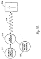
- a user drags the second amplifier control VDC 312 from the second Amplifier Panel window instance 190 into the User View window instance 170 and drops it on the master VDC 308, creating another object-to-object interaction (as shown by the dotted line and phantom VDC in FIGURE 16).
- This object-to-object interaction results in the creation of another master-slave relationship between the second amplifier control VDC 312 and the master VDC 308.
- an instance is a specific object with the behaviors defined by its class.
- An instance contains all the methods of its class, plus unique additional data. Consequently, both interface packet instances 117 and DCE instances 119 include all of the generic and class-specific methods of their class objects.
- the data of interface packet instance 117 is labeled data 612
- the generic and class-specific methods 614 are labeled 616, 618 respectively.
- the data of DCE instance 119 is labeled data 632
- the generic and class specific methods are labeled 636, 638 and 634 respectively.
- Each interface packet and DCE instance is stored in the class database located in RAM 59 of the interface 35 of the related device 21.
Landscapes
- Engineering & Computer Science (AREA)
- Software Systems (AREA)
- General Engineering & Computer Science (AREA)
- Theoretical Computer Science (AREA)
- Physics & Mathematics (AREA)
- General Physics & Mathematics (AREA)
- User Interface Of Digital Computer (AREA)
- Digital Computer Display Output (AREA)
- Selective Calling Equipment (AREA)
- Input Circuits Of Receivers And Coupling Of Receivers And Audio Equipment (AREA)
- Controls And Circuits For Display Device (AREA)
- Computer And Data Communications (AREA)
Claims (10)
- Graphisches Steuersystem zum Steuern mindestens eines rechnersystemfreien Geräts (21), umfassend:(a) ein Kommunikationsmedium (28);(b) einen an das Kommunikationsmedium (28) gekoppelten Rechner (20) mit einer Anzeige (30), einem Prozessor (60), einem Speichermedium (67, 68) und einer Benutzer-Manipulationseinrichtung (31, 32);(c) eine Schnittstelle (35) zum Koppeln des rechnersystemfreien Geräts (21) mit dem Kommunikationsmedium (28), wobei die Schnittstelle (35) einen Schnittstellenprozessor (41) und ein Schnittstellenspeichermedium (58, 59) aufweist; und(d) ein visuelles Netzwerkbetriebssystem (78) zum Steuern und Überwachen des Betriebs des Rechners (20) und der Schnittstelle (35) mit Hilfe folgender Schritte:(i) der Rechner (20) wird veranlaßt, eine einstellbare visuelle Gerätesteuerung (40) anzuzeigen, welche graphisch eine Merkmalssteuerung (29a) eines Typs repräsentiert, der normalerweise zu dem rechnersystemfreien Gerät (21) gehört, wobei die visuelle Gerätesteuerung (40) zugehörige Daten aufweist, die in dem Rechner-Speichermedium (68) gespeichert sind und die Einstellung der visuellen Gerätesteuerung (40) repräsentieren;(ii) ein Benutzer wird in die Lage versetzt, die visuelle Gerätesteuerung (40) dadurch einzustellen, daß er die Benutzer-Manipulationseinrichtung (32) auf der visuellen Gerätesteuerung (40) betätigt und eine Änderung in den Daten bewirkt, welche die Einstellung der visuellen Gerätesteuerung (40) repräsentieren;(iii) Übermitteln der Änderung der die Einstellung der visuellen Gerätesteuerung (40) repräsentierenden Daten zu der Schnittstelle (35);(iv) Veranlassen der Schnittstelle (35), das rechnersystemfreie Gerät (21) nach Maßgabe der Änderung der die Einstellung der visuellen Gerätesteuerung (40) repräsentierenden Daten einzustellen; und(v) Veranlassen des Rechners (20), eine visuelle Schablonen-Gerätesteuerung (306) anzuzeigen, welche graphisch eine hypothetische Merkmalssteuerung eines rechnersystemfreien Geräts (21) repräsentiert, welches von dem visuellen Netzwerkbetriebssystem (78) nicht gesteuert und überwacht wird.
- System nach Anspruch 1, bei dem das visuelle Netzwerkbetriebssystem (78) den Benutzer in die Lage versetzt, durch Betätigen der Benutzer-Manipulationseinrichtung (31, 32) aus der visuellen Schablonen-Gerätesteuerung (306) eine einstellbare visuelle Master-Gerätesteuerung (308) zu erzeugen, welche graphisch die hypothetische Merkmalssteuerung repräsentiert, und der in dem Rechner-Speichermedium (68) gespeicherte Daten zugeordnet sind, welche die Einstellung der visuellen Master-Gerätesteuerung (308) repräsentieren.
- System nach Anspruch 2, bei dem das visuelle Netzwerkbetriebssystem (78) den Benutzer in die Lage versetzt, die visuelle Gerätesteuerung (40) unter Verwendung der visuellen Master-Gerätesteuerung (308) durch folgende Merkmale zu regeln:(a) der Benutzer wird in die Lage versetzt, graphisch einen Dialog zwischen der visuellen Gerätesteuerung (40) und der visuellen Master-Gerätesteuerung (308) zu erzeugen, indem die Benutzer-Manipulationseinrichtung (31, 32) betätigt wird;(b) als Ergebnis des Dialogs, Einrichten einer Beziehung zwischen der visuellen Master-Gerätesteuerung (308) und der visuellen Gerätesteuerung (40), so daß:(i) eine Betätigung der Benutzer-Manipulationseinrichtung (31, 32) auf der visuellen Master-Gerätesteuerung (308) eine Änderung der die Einstellung der visuellen Master-Gerätesteuerung (308) repräsentierenden Daten bewirkt; und(ii) die Änderung der die Einstellung der visuellen Master-Gerätesteuerung (308) repräsentierenden Daten eine ähnliche Änderung derjenigen Daten bewirkt, welche die Einstellung der visuellen Gerätesteuerung (40) repräsentieren.
- System nach Anspruch 3, bei dem das visuelle Netzwerkbetriebssystem (78) den Benutzer in die Lage versetzt, mehrere visuelle Gerätesteuerungen (40) unter Verwendung der visuellen Master-Gerätesteuerung (308) zu regeln.
- System nach Anspruch 2, bei dem das visuelle Netzwerkbetriebssystem (78) den Benutzer in die Lage versetzt, vorab eine Funktion für das weitere Manipulieren der Änderung der die Einstellung der visuellen Master-Gerätesteuerung (308) repräsentierenden Daten zu definieren, so daß die manipulierte Änderung in den die Einstellung der visuellen Master-Gerätesteuerung (308) repräsentierenden Daten eine ähnliche manipulierte Änderung in den Daten bewirkt, welche die Einstellung der visuellen Gerätesteuerung (40) repräsentieren.
- Verfahren zum Steuern mindestens eines rechnersystemfreien Geräts (21), welches mindestens eine Gerätesteuerung (40) enthält, die einen Aspekt des rechnersystemfreien Geräts (21) regelt, wobei das rechnersystemfreie Gerät (21) durch eine Schnittstelle (35) an ein Kommunikationsmedium (28) gekoppelt ist und über das Kommunikationsmedium (28) an ein Rechnersystem (20) gekoppelt ist, welches eine Anzeige (30), einen Prozessor (60), ein Speichermedium (67, 68) und eine Benutzer-Manipulationseinrichtung (31, 32) aufweist, umfassend:(a) Veranlassen des Rechners (20), eine graphische Steueranzeige (40) darzustellen, die das rechnersystemfreie Gerät (21) repräsentiert und mindestens eine einstellbare graphische Steuerung (29a) enthält, die eine Merkmalssteuerung des Typs repräsentiert, der normalerweise zu dem rechnersystemfreien Gerät (21) gehört, wobei der graphischen Steuerung in dem Rechner-Speichermedium (68) abgespeicherte Daten zugeordnet sind, welche die Einstellung der graphischen Steuerung (29a) repräsentieren;(b) einem Benutzer wird ermöglicht, die graphische Steuerung (29a) durch Betätigen der Benutzer-Manipulationseinrichtung (32) auf der graphishcen Steuerung (29a) einzustellen und eine Änderung der die Einstellung der graphischen Steuerung (29a) repräsentierenden Daten zu bewirken;(c) Übermitteln der Änderung der die Einstellung der graphischen Steuerung (29a) repräsentierenden Daten an die Schnittstelle (35);(d) Veranlassen der Schnittstelle (35), das rechnersystemfreie Gerät (21) nach Maßgabe der Änderung der die Einstellung der graphischen Steuerung (29a) repräsentierenden Daten einzustellen; und(e) Veranlassen des Rechners (20), eine graphische Schablonensteuerung (306) zur Anzeige zu bringen, welche graphisch eine hypothetische Merkmalssteuerung eines rechnersystemfreien Geräts (21) repräsentiert, welches nicht mit dem Kommunikationsmedium (28) gekoppelt ist.
- Verfahren nach Anspruch 6, bei dem der Benutzer in die Lage versetzt wird, eine einstellbare graphische Master-Gerätesteuerung (308) aus der graphischen Schablonen-Steuerung (306) durch Betätigen der Benutzer-Manipulationseinrichtung (32) zu erzeugen, wobei die graphische Master-Gerätesteuerung (308) graphisch die hypothetische Merkmalssteuerung repräsentiert, und der graphischen Master-Gerätesteuerung (308) in dem Rechner-Speichermedium (68) gespeicherte Daten zugeordnet sind, die die Einstellung der graphischen Master-Gerätesteuerung (308) repräsentieren.
- Verfahren nach Anspruch 7, bei dem der Benutzer in die Lage versetzt wird, die graphische Master-Gerätesteuerung (308) zum Regeln der graphischen Steuerung (29a) zu verwenden, wobei dieses In-die-Lage-Versetzen des Benutzers zur Verwendung der graphischen Master-Gerätesteuerung (308) beinhaltet:(a) der Benutzer wird in die Lage versetzt, graphisch einen Dialog zwischen der graphischen Steuerung (29a) und der graphischen Master-Gerätesteuerung (308) durch Betätigen der Benutzer-Manipulationseinrichtung (32) zu erzeugen;(b) als Ergebnis des Dialogs wird eine Beziehung zwischen der graphischen Master-Gerätesteuerung (308) und der graphischen Steuerung (29a) eingerichtet;(c) als Ergebnis der Relation zwischen der graphischen Master-Gerätesteuerung (308) und der graphischen Steuerung (29a) wird der Benutzer in die Lage versetzt, eine Änderung der die Einstellung der graphischen Master-Gerätesteuerung (308) repräsentierenden Daten durch Betätigen der Benutzer-Manipulationseinrichtung (32) zu bewirken, wobei die Änderung der die Einstellung der graphischen Master-Gerätesteuerung (308) repräsentierenden Daten auch eine ähnliche Änderung der Daten bewirkt, welche die Einstellung der graphischen Steuerung (29a) repräsentieren.
- Verfahren nach Anspruch 8, bei dem das In-die-Lage-Versetzen des Benutzers zum Bewirken einer Änderung der die Einstellung der graphischen Master-Gerätesteuerung (308) repräsentierenden Daten außerdem beinhaltet, daß der Benutzer vorab eine Funktion zum zusätzlichen Manipulieren der Änderung der die Einstellung der graphischen Master-Gerätesteuerung (308) definiert.
- Verfahren nach Anspruch 8, bei dem der Benutzer in die Lage versetzt wird, die graphische Master-Gerätesteuerung (308) dazu zu benutzen, mehrere graphische Steuerungen (29a) zu regeln, wobei das In-die-Lage-Versetzen des Benutzers, die graphische Master-Gerätesteuerung (308) zu verwenden, beinhaltet:
für jede graphische Steuerung (29a):(a) dem Benutzer wird ermöglicht, graphisch durch Betätigen der Benutzer-Manipulationseinrichtung (32) einen Dialog zwischen der graphischen Master-Gerätesteuerung (308) und der graphischen Steuerung (29a) zu erzeugen;(b) als Ergebnis des Dialogs wird eine Relation zwischen der graphischen Master-Gerätesteuerung (308) und der graphischen Steuerung (29a) eingerichtet;(c) als Ergebnis der Relation zwischen der graphischen Master-Gerätesteuerung (308) und der graphischen Steuerung (29a) wird der Benutzer in die Lage versetzt, eine Änderung der die Einstellung der graphischen Master-Gerätesteuerung (308) repräsentierenden Daten durch Betätigen der Benutzer-Manipulationseinrichtung (32) zu bewirken, wobei die Änderung der die Einstellung der graphischen Master-Gerätesteuerung (308) repräsentierenden Daten auch eine ähnliche Änderung derjenigen Daten bewirkt, die die Einstellung der graphischen Steuerung (29a) repräsentieren.
Applications Claiming Priority (3)
| Application Number | Priority Date | Filing Date | Title |
|---|---|---|---|
| US08/334,416 US5657221A (en) | 1994-09-16 | 1994-11-04 | Method and apparatus for controlling non-computer system devices by manipulating a graphical representation |
| US334416 | 1994-11-04 | ||
| EP95930855A EP0789874B1 (de) | 1994-11-04 | 1995-08-17 | Verfahren und gerät zur steuerung von non-rechner-systemeinrichtungen durch manipulieren einer graphischen oberfläche |
Related Parent Applications (1)
| Application Number | Title | Priority Date | Filing Date |
|---|---|---|---|
| EP95930855A Division EP0789874B1 (de) | 1994-11-04 | 1995-08-17 | Verfahren und gerät zur steuerung von non-rechner-systemeinrichtungen durch manipulieren einer graphischen oberfläche |
Publications (3)
| Publication Number | Publication Date |
|---|---|
| EP0921463A2 EP0921463A2 (de) | 1999-06-09 |
| EP0921463A3 EP0921463A3 (de) | 1999-09-08 |
| EP0921463B1 true EP0921463B1 (de) | 2001-10-31 |
Family
ID=23307113
Family Applications (3)
| Application Number | Title | Priority Date | Filing Date |
|---|---|---|---|
| EP99104744A Expired - Lifetime EP0933700B1 (de) | 1994-11-04 | 1995-08-17 | Verfahren und Gerät zur Steuerung von Non-Rechner-Systemeinrichtungen durch Manipulieren einer graphischen Oberfläche |
| EP95930855A Expired - Lifetime EP0789874B1 (de) | 1994-11-04 | 1995-08-17 | Verfahren und gerät zur steuerung von non-rechner-systemeinrichtungen durch manipulieren einer graphischen oberfläche |
| EP99104745A Expired - Lifetime EP0921463B1 (de) | 1994-11-04 | 1995-08-17 | Verfahren und Gerät zur Steuerung von nicht immanenten Rechner-Systemeinrichtungen mittels graphischen Oberfläche |
Family Applications Before (2)
| Application Number | Title | Priority Date | Filing Date |
|---|---|---|---|
| EP99104744A Expired - Lifetime EP0933700B1 (de) | 1994-11-04 | 1995-08-17 | Verfahren und Gerät zur Steuerung von Non-Rechner-Systemeinrichtungen durch Manipulieren einer graphischen Oberfläche |
| EP95930855A Expired - Lifetime EP0789874B1 (de) | 1994-11-04 | 1995-08-17 | Verfahren und gerät zur steuerung von non-rechner-systemeinrichtungen durch manipulieren einer graphischen oberfläche |
Country Status (7)
| Country | Link |
|---|---|
| US (1) | US5657221A (de) |
| EP (3) | EP0933700B1 (de) |
| JP (1) | JPH10508711A (de) |
| AT (3) | ATE208063T1 (de) |
| CA (1) | CA2204113A1 (de) |
| DE (3) | DE69524460T2 (de) |
| WO (1) | WO1996014618A1 (de) |
Families Citing this family (120)
| Publication number | Priority date | Publication date | Assignee | Title |
|---|---|---|---|---|
| US10361802B1 (en) | 1999-02-01 | 2019-07-23 | Blanding Hovenweep, Llc | Adaptive pattern recognition based control system and method |
| EP0626635B1 (de) * | 1993-05-24 | 2003-03-05 | Sun Microsystems, Inc. | Graphische Benutzerschnittstelle mit Verfahren zur Schnittstellebildung mit fernsteuernden Einrichtungen |
| US5966125A (en) * | 1996-12-10 | 1999-10-12 | Environique, Inc. | System and method for dynamic controls |
| US5872722A (en) * | 1996-09-04 | 1999-02-16 | Eaton Corporation | Apparatus and method for adjustment and coordination of circuit breaker trip curves through graphical manipulation |
| US6298196B1 (en) | 1996-09-05 | 2001-10-02 | Sony Corporation | Digital recording apparatus and copyright protection method thereof |
| US5831613A (en) * | 1997-01-06 | 1998-11-03 | Apple Computer, Inc. | Removable storage media stop/eject system for personal computers |
| JP3870983B2 (ja) | 1997-02-17 | 2007-01-24 | ソニー株式会社 | 電子機器制御装置および方法、並びに電子機器 |
| EP0872991B1 (de) * | 1997-04-15 | 2006-07-26 | Hewlett-Packard Company, A Delaware Corporation | Verfahren und Vorrichtung zur formatgesteuerten Interaktion zwischen Geräten |
| JPH117315A (ja) * | 1997-04-21 | 1999-01-12 | Toshiba Corp | 監視・制御システム及びその処理内容を記録した媒体 |
| US6081266A (en) * | 1997-04-21 | 2000-06-27 | Sony Corporation | Interactive control of audio outputs on a display screen |
| US5990884A (en) * | 1997-05-02 | 1999-11-23 | Sony Corporation | Control of multimedia information with interface specification stored on multimedia component |
| JP4367971B2 (ja) * | 1997-06-05 | 2009-11-18 | ソニー株式会社 | 電子機器制御装置、電子機器制御方法、および電子機器 |
| ES2235340T3 (es) * | 1997-06-25 | 2005-07-01 | Samsung Electronics Co. Ltd. | Generacion de guia de progrmas para redes domesticas. |
| CN100367713C (zh) * | 1997-07-30 | 2008-02-06 | 索尼电子有限公司 | 描述人为接口特性和基于av/c的设备的功能度的方法 |
| US6311149B1 (en) | 1997-08-18 | 2001-10-30 | National Instruments Corporation | Reconfigurable test system |
| US6802053B1 (en) | 1997-08-18 | 2004-10-05 | National Instruments Corporation | Graphical programming system with distributed block diagram execution and front panel display |
| US6173438B1 (en) | 1997-08-18 | 2001-01-09 | National Instruments Corporation | Embedded graphical programming system |
| US6577326B1 (en) * | 1997-08-29 | 2003-06-10 | Koninklijke Philips Electronics N.V. | Computer-controlled home theater independent user-control |
| DE19742637C5 (de) * | 1997-09-26 | 2005-06-02 | Fresenius Medical Care Deutschland Gmbh | Vorrichtung und Verfahren zur Bedienung medizintechnischer Geräte |
| JPH11150788A (ja) * | 1997-11-14 | 1999-06-02 | Yamaha Corp | オーディオシステム |
| US5945993A (en) * | 1998-01-30 | 1999-08-31 | Hewlett-Packard Company | Pictograph-based method and apparatus for controlling a plurality of lighting loads |
| US7152027B2 (en) | 1998-02-17 | 2006-12-19 | National Instruments Corporation | Reconfigurable test system |
| US7085670B2 (en) | 1998-02-17 | 2006-08-01 | National Instruments Corporation | Reconfigurable measurement system utilizing a programmable hardware element and fixed hardware resources |
| US7043532B1 (en) * | 1998-05-07 | 2006-05-09 | Samsung Electronics Co., Ltd. | Method and apparatus for universally accessible command and control information in a network |
| ATE300834T1 (de) * | 1998-05-07 | 2005-08-15 | Samsung Electronics Co Ltd | Verfahren und vorrichtung für universellen zugriffsbefehl und kontrollinformation in einem netzwerk |
| KR100385967B1 (ko) * | 1998-05-23 | 2003-07-16 | 삼성전자주식회사 | 네트웍상에서의서버기기접속방법 |
| US6061602A (en) * | 1998-06-23 | 2000-05-09 | Creative Lifestyles, Inc. | Method and apparatus for developing application software for home automation system |
| US7865832B2 (en) * | 1999-07-26 | 2011-01-04 | Sony Corporation | Extended elements and mechanisms for displaying a rich graphical user interface in panel subunit |
| US6381507B1 (en) * | 1998-07-01 | 2002-04-30 | Sony Corporation | Command pass-through functionality in panel subunit |
| US6456892B1 (en) * | 1998-07-01 | 2002-09-24 | Sony Electronics, Inc. | Data driven interaction for networked control of a DDI target device over a home entertainment network |
| US6295479B1 (en) * | 1998-07-01 | 2001-09-25 | Sony Corporation Of Japan | Focus in/out actions and user action pass-through mechanism for panel subunit |
| US6148241A (en) * | 1998-07-01 | 2000-11-14 | Sony Corporation Of Japan | Method and system for providing a user interface for a networked device using panel subunit descriptor information |
| US6556221B1 (en) * | 1998-07-01 | 2003-04-29 | Sony Corporation | Extended elements and mechanisms for displaying a rich graphical user interface in panel subunit |
| US6615293B1 (en) | 1998-07-01 | 2003-09-02 | Sony Corporation | Method and system for providing an exact image transfer and a root panel list within the panel subunit graphical user interface mechanism |
| JP2000197159A (ja) * | 1998-12-28 | 2000-07-14 | Sanyo Electric Co Ltd | 音響・映像コントロ―ルシステム |
| JP4508330B2 (ja) * | 1999-01-25 | 2010-07-21 | キヤノン株式会社 | 表示装置 |
| US7904187B2 (en) | 1999-02-01 | 2011-03-08 | Hoffberg Steven M | Internet appliance system and method |
| JP2000261482A (ja) | 1999-03-08 | 2000-09-22 | Sony Corp | アドレス設定方法、クライアント装置、サーバ装置、並びにクライアントサーバシステム |
| US7213061B1 (en) | 1999-04-29 | 2007-05-01 | Amx Llc | Internet control system and method |
| JP2000332801A (ja) * | 1999-05-19 | 2000-11-30 | Matsushita Electric Ind Co Ltd | 仮想avネットワーク構築装置、及び仮想avネットワーク構築方法、並びに仮想avネットワーク構築方法に関するプログラムを記載した記録媒体 |
| US6657646B2 (en) | 1999-06-08 | 2003-12-02 | Amx Corporation | System and method for multimedia display |
| JP4147689B2 (ja) | 1999-06-14 | 2008-09-10 | ソニー株式会社 | 情報処理装置及び情報処理方法 |
| US6775244B1 (en) * | 1999-06-21 | 2004-08-10 | Intel Corporation | Gathering of device discovery information |
| US6831704B1 (en) * | 1999-07-30 | 2004-12-14 | Grass Valley (U.S.) Inc. | Linking external devices to switcher transitions |
| JP2001066986A (ja) * | 1999-08-26 | 2001-03-16 | Sony Corp | 送信装置および方法、受信装置および方法、通信システム、並びにプログラム格納媒体 |
| JP2001077831A (ja) | 1999-09-08 | 2001-03-23 | Sony Corp | 通信制御装置および方法、通信システム、並びにプログラム格納媒体 |
| JP4168304B2 (ja) * | 1999-09-16 | 2008-10-22 | ソニー株式会社 | 情報出力装置、情報報知方法および情報信号供給経路選択方法 |
| US7187947B1 (en) * | 2000-03-28 | 2007-03-06 | Affinity Labs, Llc | System and method for communicating selected information to an electronic device |
| US6674452B1 (en) | 2000-04-05 | 2004-01-06 | International Business Machines Corporation | Graphical user interface to query music by examples |
| US6225546B1 (en) | 2000-04-05 | 2001-05-01 | International Business Machines Corporation | Method and apparatus for music summarization and creation of audio summaries |
| US7047495B1 (en) | 2000-06-30 | 2006-05-16 | Intel Corporation | Method and apparatus for graphical device management using a virtual console |
| US20020046266A1 (en) * | 2000-08-09 | 2002-04-18 | Muralidhar Kurudi H. | Computer-implemented method and apparatus for the cloning of input/output devices |
| US6643555B1 (en) * | 2000-10-10 | 2003-11-04 | Schneider Automation Inc. | Method and apparatus for generating an application for an automation control system |
| US8480466B2 (en) | 2001-03-27 | 2013-07-09 | Igt | Method and apparatus for previewing a game |
| US7918738B2 (en) | 2001-03-27 | 2011-04-05 | Igt | Interactive game playing preferences |
| AU2002316435B2 (en) | 2001-06-27 | 2008-02-21 | Skky, Llc | Improved media delivery platform |
| US20030088852A1 (en) * | 2001-11-07 | 2003-05-08 | Lone Wolf Technologies Corporation. | Visual network operating system and methods |
| US7390257B2 (en) * | 2001-12-06 | 2008-06-24 | Igt | Programmable computer controlled external visual indicator for gaming machine |
| US7203930B1 (en) * | 2001-12-31 | 2007-04-10 | Bellsouth Intellectual Property Corp. | Graphical interface system monitor providing error notification message with modifiable indication of severity |
| EP1481305A2 (de) * | 2002-02-28 | 2004-12-01 | Agfa-Gevaert | Verfahren zur einstellung einer benutzerschnittstelle in einem druckvorbereitungs-arbeitsfluss |
| US7788346B2 (en) * | 2002-03-01 | 2010-08-31 | Oracle America, Inc. | System and method for state data back-up in a distributed data system |
| AU2003231085A1 (en) * | 2002-04-24 | 2003-11-10 | Victor I. Marmon | Method and system for graphical data representation |
| US7343566B1 (en) | 2002-07-10 | 2008-03-11 | Apple Inc. | Method and apparatus for displaying a window for a user interface |
| US20040021698A1 (en) * | 2002-08-05 | 2004-02-05 | Baldwin Amanda K. | Intuitive touchscreen interface for a multifunction device and method therefor |
| US7224366B2 (en) | 2002-10-17 | 2007-05-29 | Amx, Llc | Method and system for control system software |
| AU2003214266A1 (en) * | 2003-03-10 | 2004-09-30 | Eneo Laboratories, S.A. | Interactive system and method for controlling household appliances |
| US7610553B1 (en) * | 2003-04-05 | 2009-10-27 | Apple Inc. | Method and apparatus for reducing data events that represent a user's interaction with a control interface |
| US7328412B1 (en) * | 2003-04-05 | 2008-02-05 | Apple Inc. | Method and apparatus for displaying a gain control interface with non-linear gain levels |
| JP2006514808A (ja) * | 2003-06-10 | 2006-05-11 | ハーマン インターナショナル インダストリーズ インコーポレイテッド | ローカルインターフェースシステムを有する音声増幅器 |
| US7200529B2 (en) * | 2003-08-15 | 2007-04-03 | National Instruments Corporation | Automatic configuration of function blocks in a signal analysis system |
| US20050138546A1 (en) * | 2003-12-23 | 2005-06-23 | Microsoft Corporation | Personalized web page on a home network for viewing on a television |
| US20050140696A1 (en) * | 2003-12-31 | 2005-06-30 | Buxton William A.S. | Split user interface |
| US8473844B2 (en) * | 2004-03-26 | 2013-06-25 | Harman International Industries, Incorporated | Audio related system link management |
| DE102004023200A1 (de) * | 2004-05-11 | 2005-12-08 | Siemens Ag | Verfahren zum Erzeugen eines virtuellen Anzeige- oder Bediengeräts |
| US8468219B2 (en) * | 2005-02-01 | 2013-06-18 | Broadcom Corporation | Minimum intervention authentication of heterogeneous network technologies (MIAHNT) |
| TWI265458B (en) * | 2005-06-02 | 2006-11-01 | Avermedia Tech Inc | Audio player |
| US20070055740A1 (en) * | 2005-08-23 | 2007-03-08 | Luciani Luis E | System and method for interacting with a remote computer |
| EP1934720B1 (de) | 2005-09-07 | 2018-02-14 | Open Invention Network LLC | Verfahren und computerprogramm zur einrichtungskonfiguration |
| KR101053852B1 (ko) * | 2006-03-10 | 2011-08-03 | 삼성전자주식회사 | 거치장치, 휴대용 단말기 및 그 제어방법 |
| US7934194B2 (en) * | 2006-10-17 | 2011-04-26 | The Mathworks, Inc. | User-defined hierarchies of user-defined classes of graphical objects in a graphical modeling environment |
| US8096884B2 (en) * | 2006-11-09 | 2012-01-17 | Igt | Gaming machine with adjustable button panel |
| US7833102B2 (en) * | 2006-11-09 | 2010-11-16 | Igt | Gaming machine with consolidated peripherals |
| US20080113716A1 (en) * | 2006-11-09 | 2008-05-15 | Igt | Personalization of video and sound presentation on a gaming machine |
| US20080113821A1 (en) * | 2006-11-09 | 2008-05-15 | Igt | Gaming machine with vertical door-mounted display |
| US8177637B2 (en) * | 2006-11-09 | 2012-05-15 | Igt | Button panel control for a gaming machine |
| US8839142B2 (en) | 2007-06-08 | 2014-09-16 | Apple Inc. | Desktop system object removal |
| EP2186035B1 (de) * | 2007-06-29 | 2018-12-26 | Roche Diabetes Care GmbH | Vorrichtung und verfahren zur fernsteuerung eines ambulanten medizinischen geräts |
| EP2028882B1 (de) * | 2007-08-01 | 2018-10-10 | Yamaha Corporation | Fernüberwachungssystem für Audioverstärker in einem Netzwerk |
| KR101456570B1 (ko) * | 2007-12-21 | 2014-10-31 | 엘지전자 주식회사 | 디지털 이퀄라이저를 구비한 이동 단말기 및 그 제어방법 |
| US8458667B2 (en) | 2008-01-30 | 2013-06-04 | National Instruments Corporation | Debugging a statechart for a real time target |
| US20090195513A1 (en) * | 2008-02-05 | 2009-08-06 | Delphi Technologies, Inc. | Interactive multimedia control module |
| JP5200095B2 (ja) * | 2008-02-27 | 2013-05-15 | 京セラ株式会社 | ユーザインタフェース生成装置 |
| DE102008055585B3 (de) * | 2008-12-23 | 2010-04-29 | Jiri Burda | Modulares Heiz- und Beleuchtungssystem zum Aufbau von Leucht- und Heizelementen |
| US8687777B1 (en) | 2010-02-03 | 2014-04-01 | Tal Lavian | Systems and methods for visual presentation and selection of IVR menu |
| US9001819B1 (en) | 2010-02-18 | 2015-04-07 | Zvi Or-Bach | Systems and methods for visual presentation and selection of IVR menu |
| US8903073B2 (en) | 2011-07-20 | 2014-12-02 | Zvi Or-Bach | Systems and methods for visual presentation and selection of IVR menu |
| US8553859B1 (en) | 2010-02-03 | 2013-10-08 | Tal Lavian | Device and method for providing enhanced telephony |
| US8625756B1 (en) | 2010-02-03 | 2014-01-07 | Tal Lavian | Systems and methods for visual presentation and selection of IVR menu |
| US8594280B1 (en) | 2010-02-03 | 2013-11-26 | Zvi Or-Bach | Systems and methods for visual presentation and selection of IVR menu |
| US8572303B2 (en) * | 2010-02-03 | 2013-10-29 | Tal Lavian | Portable universal communication device |
| US8537989B1 (en) | 2010-02-03 | 2013-09-17 | Tal Lavian | Device and method for providing enhanced telephony |
| US8879698B1 (en) | 2010-02-03 | 2014-11-04 | Tal Lavian | Device and method for providing enhanced telephony |
| US8681951B1 (en) | 2010-02-03 | 2014-03-25 | Tal Lavian | Systems and methods for visual presentation and selection of IVR menu |
| US8406388B2 (en) | 2011-07-18 | 2013-03-26 | Zvi Or-Bach | Systems and methods for visual presentation and selection of IVR menu |
| US8548135B1 (en) | 2010-02-03 | 2013-10-01 | Tal Lavian | Systems and methods for visual presentation and selection of IVR menu |
| US8548131B1 (en) | 2010-02-03 | 2013-10-01 | Tal Lavian | Systems and methods for communicating with an interactive voice response system |
| KR101698354B1 (ko) | 2010-07-16 | 2017-01-23 | 삼성전자주식회사 | 홈 네트워크에서 멀티캐스트 메시지를 이용하여 복수 개의 원격 사용자 인터페이스 서버들을 제어하기 위한 장치 및 방법 |
| US9661428B2 (en) * | 2010-08-17 | 2017-05-23 | Harman International Industries, Inc. | System for configuration and management of live sound system |
| US8910065B2 (en) * | 2010-09-14 | 2014-12-09 | Microsoft Corporation | Secondary output generation from a presentation framework |
| US9292196B2 (en) | 2010-10-19 | 2016-03-22 | Apple Inc. | Modifying the presentation of clustered application windows in a user interface |
| US9542202B2 (en) | 2010-10-19 | 2017-01-10 | Apple Inc. | Displaying and updating workspaces in a user interface |
| US9658732B2 (en) | 2010-10-19 | 2017-05-23 | Apple Inc. | Changing a virtual workspace based on user interaction with an application window in a user interface |
| US10740117B2 (en) | 2010-10-19 | 2020-08-11 | Apple Inc. | Grouping windows into clusters in one or more workspaces in a user interface |
| US10152192B2 (en) | 2011-02-21 | 2018-12-11 | Apple Inc. | Scaling application windows in one or more workspaces in a user interface |
| DE102011017729A1 (de) * | 2011-04-28 | 2012-10-31 | Zumtobel Lighting Gmbh | Bedienelement für eine Beleuchtungsanlage |
| US8731148B1 (en) | 2012-03-02 | 2014-05-20 | Tal Lavian | Systems and methods for visual presentation and selection of IVR menu |
| US8867708B1 (en) | 2012-03-02 | 2014-10-21 | Tal Lavian | Systems and methods for visual presentation and selection of IVR menu |
| DE102013202020A1 (de) | 2013-02-07 | 2014-08-07 | Robert Bosch Gmbh | Graphisches Bildschirmelement |
| US9286429B2 (en) * | 2013-12-31 | 2016-03-15 | Alcatel Lucent | System and method for amplifier design |
| US9633642B2 (en) | 2015-07-24 | 2017-04-25 | Roland Corporation | Electronic musical instrument system |
Family Cites Families (9)
| Publication number | Priority date | Publication date | Assignee | Title |
|---|---|---|---|---|
| US4279012A (en) * | 1978-10-23 | 1981-07-14 | Massachusetts Microcomputers, Inc. | Programmable appliance controller |
| US4849880A (en) * | 1985-11-18 | 1989-07-18 | John Fluke Mfg. Co., Inc. | Virtual machine programming system |
| US5062060A (en) * | 1987-01-05 | 1991-10-29 | Motorola Inc. | Computer human interface comprising user-adjustable window for displaying or printing information |
| US5335323A (en) * | 1987-01-05 | 1994-08-02 | Motorola, Inc. | Computer human interface with multiapplication display |
| US5021976A (en) * | 1988-11-14 | 1991-06-04 | Microelectronics And Computer Technology Corporation | Method and system for generating dynamic, interactive visual representations of information structures within a computer |
| US5086385A (en) * | 1989-01-31 | 1992-02-04 | Custom Command Systems | Expandable home automation system |
| US5400246A (en) * | 1989-05-09 | 1995-03-21 | Ansan Industries, Ltd. | Peripheral data acquisition, monitor, and adaptive control system via personal computer |
| US5321829A (en) * | 1990-07-20 | 1994-06-14 | Icom, Inc. | Graphical interfaces for monitoring ladder logic programs |
| EP0596594B1 (de) * | 1992-10-26 | 2000-07-12 | Sun Microsystems, Inc. | Fernbedienungs- und Zeigegerät |
-
1994
- 1994-11-04 US US08/334,416 patent/US5657221A/en not_active Expired - Fee Related
-
1995
- 1995-08-17 AT AT99104745T patent/ATE208063T1/de not_active IP Right Cessation
- 1995-08-17 CA CA002204113A patent/CA2204113A1/en not_active Abandoned
- 1995-08-17 AT AT99104744T patent/ATE210315T1/de not_active IP Right Cessation
- 1995-08-17 EP EP99104744A patent/EP0933700B1/de not_active Expired - Lifetime
- 1995-08-17 EP EP95930855A patent/EP0789874B1/de not_active Expired - Lifetime
- 1995-08-17 AT AT95930855T patent/ATE185629T1/de not_active IP Right Cessation
- 1995-08-17 DE DE69524460T patent/DE69524460T2/de not_active Expired - Fee Related
- 1995-08-17 EP EP99104745A patent/EP0921463B1/de not_active Expired - Lifetime
- 1995-08-17 JP JP8514886A patent/JPH10508711A/ja active Pending
- 1995-08-17 DE DE69523645T patent/DE69523645T2/de not_active Expired - Fee Related
- 1995-08-17 DE DE69512799T patent/DE69512799T2/de not_active Expired - Fee Related
- 1995-08-17 WO PCT/US1995/010527 patent/WO1996014618A1/en not_active Ceased
Also Published As
| Publication number | Publication date |
|---|---|
| DE69523645D1 (de) | 2001-12-06 |
| EP0933700B1 (de) | 2001-12-05 |
| DE69512799D1 (de) | 1999-11-18 |
| CA2204113A1 (en) | 1996-05-17 |
| US5657221A (en) | 1997-08-12 |
| EP0921463A2 (de) | 1999-06-09 |
| EP0933700A1 (de) | 1999-08-04 |
| WO1996014618A1 (en) | 1996-05-17 |
| EP0789874B1 (de) | 1999-10-13 |
| DE69512799T2 (de) | 2000-05-11 |
| DE69523645T2 (de) | 2002-06-20 |
| ATE185629T1 (de) | 1999-10-15 |
| JPH10508711A (ja) | 1998-08-25 |
| DE69524460T2 (de) | 2002-08-01 |
| ATE208063T1 (de) | 2001-11-15 |
| DE69524460D1 (de) | 2002-01-17 |
| EP0789874A1 (de) | 1997-08-20 |
| ATE210315T1 (de) | 2001-12-15 |
| EP0921463A3 (de) | 1999-09-08 |
Similar Documents
| Publication | Publication Date | Title |
|---|---|---|
| EP0921463B1 (de) | Verfahren und Gerät zur Steuerung von nicht immanenten Rechner-Systemeinrichtungen mittels graphischen Oberfläche | |
| CA2330693C (en) | Control system, display, host computer for control, and data transmitting method | |
| US5929855A (en) | Monitoring and control system using graphical representations with prelinked parameters for devices within a network | |
| JP2938374B2 (ja) | 順序シーケンス・プログラムの作成装置及び制御装置 | |
| JP4659986B2 (ja) | 十分な機能を有する遠隔制御のエディタ及びエミュレータ | |
| EP0602947A1 (de) | Multimedia-System mit Software-Mechanismen für Standard-Schnittstellen und -Kontrolle zum Betrieb von Multimedia-Geräten | |
| JP2009009560A (ja) | 図形要素を用いてプロセスコントロール環境を構成するためのシステム | |
| US5708786A (en) | Data processing device having event in non-windows desktop environment affecting window in desktop environment | |
| US20030088852A1 (en) | Visual network operating system and methods | |
| US6335745B1 (en) | Method and system for invoking a function of a graphical object in a graphical user interface | |
| KR0140548B1 (ko) | 다중 파라메터 범위의 그래픽적 설정 방법 및 장치 | |
| JP2625649B2 (ja) | コンピュータ・オブジェクトを伝送するためのシステム及び方法 | |
| US7239316B1 (en) | Method and apparatus for graphically manipulating data tables | |
| EP0745927B1 (de) | Methode und Editiersystem zur Stellung einer Werkzeugtaste | |
| JPH09134272A (ja) | マルチメディア・データを処理するオブジェクト指向方法及び装置 | |
| CN116954384A (zh) | 自定义软键盘的实现方法、装置、电子设备及存储介质 | |
| JP3923821B2 (ja) | 画像処理システム及び画像処理装置に接続可能な表示装置 | |
| Dettmer | X Windows-the great integrator | |
| JP7615420B1 (ja) | シミュレーションプログラム、シミュレーション装置、シミュレーションシステム及び表示方法 | |
| US7149979B2 (en) | Data management system and method for peripheral devices | |
| CN117519701A (zh) | 一种基于Web可编程设计的HMI系统 | |
| JP2907277B2 (ja) | 監視制御システムのユーザインタフェースシステム | |
| JPS6231479A (ja) | 画像識別子による情報処理方式 | |
| CN117791279A (zh) | 一种激光器输出功率控制方法、系统、终端及介质 | |
| CN117742839A (zh) | 数据调用方法、装置、设备及存储介质 |
Legal Events
| Date | Code | Title | Description |
|---|---|---|---|
| PUAI | Public reference made under article 153(3) epc to a published international application that has entered the european phase |
Free format text: ORIGINAL CODE: 0009012 |
|
| 17P | Request for examination filed |
Effective date: 19990310 |
|
| AC | Divisional application: reference to earlier application |
Ref document number: 789874 Country of ref document: EP |
|
| AK | Designated contracting states |
Kind code of ref document: A2 Designated state(s): AT BE CH DE DK ES FR GB GR IE IT LI LU MC NL PT SE |
|
| PUAL | Search report despatched |
Free format text: ORIGINAL CODE: 0009013 |
|
| AK | Designated contracting states |
Kind code of ref document: A3 Designated state(s): AT BE CH DE DK ES FR GB GR IE IT LI LU MC NL PT SE |
|
| RIN1 | Information on inventor provided before grant (corrected) |
Inventor name: COCO, GEOFFREY P. Inventor name: LUCAS, MARK A. Inventor name: WARMAN, DAVID J. |
|
| 17Q | First examination report despatched |
Effective date: 20000502 |
|
| GRAG | Despatch of communication of intention to grant |
Free format text: ORIGINAL CODE: EPIDOS AGRA |
|
| GRAG | Despatch of communication of intention to grant |
Free format text: ORIGINAL CODE: EPIDOS AGRA |
|
| GRAH | Despatch of communication of intention to grant a patent |
Free format text: ORIGINAL CODE: EPIDOS IGRA |
|
| GRAH | Despatch of communication of intention to grant a patent |
Free format text: ORIGINAL CODE: EPIDOS IGRA |
|
| GRAA | (expected) grant |
Free format text: ORIGINAL CODE: 0009210 |
|
| DAX | Request for extension of the european patent (deleted) | ||
| AC | Divisional application: reference to earlier application |
Ref document number: 789874 Country of ref document: EP |
|
| AK | Designated contracting states |
Kind code of ref document: B1 Designated state(s): AT BE CH DE DK ES FR GB GR IE IT LI LU MC NL PT SE |
|
| PG25 | Lapsed in a contracting state [announced via postgrant information from national office to epo] |
Ref country code: NL Free format text: LAPSE BECAUSE OF FAILURE TO SUBMIT A TRANSLATION OF THE DESCRIPTION OR TO PAY THE FEE WITHIN THE PRESCRIBED TIME-LIMIT Effective date: 20011031 Ref country code: LI Free format text: LAPSE BECAUSE OF FAILURE TO SUBMIT A TRANSLATION OF THE DESCRIPTION OR TO PAY THE FEE WITHIN THE PRESCRIBED TIME-LIMIT Effective date: 20011031 Ref country code: IT Free format text: LAPSE BECAUSE OF FAILURE TO SUBMIT A TRANSLATION OF THE DESCRIPTION OR TO PAY THE FEE WITHIN THE PRESCRIBED TIME-LIMIT;WARNING: LAPSES OF ITALIAN PATENTS WITH EFFECTIVE DATE BEFORE 2007 MAY HAVE OCCURRED AT ANY TIME BEFORE 2007. THE CORRECT EFFECTIVE DATE MAY BE DIFFERENT FROM THE ONE RECORDED. Effective date: 20011031 Ref country code: CH Free format text: LAPSE BECAUSE OF FAILURE TO SUBMIT A TRANSLATION OF THE DESCRIPTION OR TO PAY THE FEE WITHIN THE PRESCRIBED TIME-LIMIT Effective date: 20011031 Ref country code: BE Free format text: LAPSE BECAUSE OF FAILURE TO SUBMIT A TRANSLATION OF THE DESCRIPTION OR TO PAY THE FEE WITHIN THE PRESCRIBED TIME-LIMIT Effective date: 20011031 Ref country code: AT Free format text: LAPSE BECAUSE OF FAILURE TO SUBMIT A TRANSLATION OF THE DESCRIPTION OR TO PAY THE FEE WITHIN THE PRESCRIBED TIME-LIMIT Effective date: 20011031 |
|
| REF | Corresponds to: |
Ref document number: 208063 Country of ref document: AT Date of ref document: 20011115 Kind code of ref document: T |
|
| REG | Reference to a national code |
Ref country code: CH Ref legal event code: EP |
|
| REF | Corresponds to: |
Ref document number: 69523645 Country of ref document: DE Date of ref document: 20011206 |
|
| REG | Reference to a national code |
Ref country code: IE Ref legal event code: FG4D |
|
| REG | Reference to a national code |
Ref country code: GB Ref legal event code: IF02 |
|
| PG25 | Lapsed in a contracting state [announced via postgrant information from national office to epo] |
Ref country code: SE Free format text: LAPSE BECAUSE OF FAILURE TO SUBMIT A TRANSLATION OF THE DESCRIPTION OR TO PAY THE FEE WITHIN THE PRESCRIBED TIME-LIMIT Effective date: 20020131 Ref country code: PT Free format text: LAPSE BECAUSE OF FAILURE TO SUBMIT A TRANSLATION OF THE DESCRIPTION OR TO PAY THE FEE WITHIN THE PRESCRIBED TIME-LIMIT Effective date: 20020131 Ref country code: DK Free format text: LAPSE BECAUSE OF FAILURE TO SUBMIT A TRANSLATION OF THE DESCRIPTION OR TO PAY THE FEE WITHIN THE PRESCRIBED TIME-LIMIT Effective date: 20020131 |
|
| PG25 | Lapsed in a contracting state [announced via postgrant information from national office to epo] |
Ref country code: GR Free format text: LAPSE BECAUSE OF FAILURE TO SUBMIT A TRANSLATION OF THE DESCRIPTION OR TO PAY THE FEE WITHIN THE PRESCRIBED TIME-LIMIT Effective date: 20020201 |
|
| NLV1 | Nl: lapsed or annulled due to failure to fulfill the requirements of art. 29p and 29m of the patents act | ||
| ET | Fr: translation filed | ||
| PG25 | Lapsed in a contracting state [announced via postgrant information from national office to epo] |
Ref country code: ES Free format text: LAPSE BECAUSE OF FAILURE TO SUBMIT A TRANSLATION OF THE DESCRIPTION OR TO PAY THE FEE WITHIN THE PRESCRIBED TIME-LIMIT Effective date: 20020430 |
|
| REG | Reference to a national code |
Ref country code: CH Ref legal event code: PL |
|
| PG25 | Lapsed in a contracting state [announced via postgrant information from national office to epo] |
Ref country code: LU Free format text: LAPSE BECAUSE OF NON-PAYMENT OF DUE FEES Effective date: 20020817 Ref country code: GB Free format text: LAPSE BECAUSE OF NON-PAYMENT OF DUE FEES Effective date: 20020817 |
|
| PG25 | Lapsed in a contracting state [announced via postgrant information from national office to epo] |
Ref country code: IE Free format text: LAPSE BECAUSE OF NON-PAYMENT OF DUE FEES Effective date: 20020819 |
|
| PLBE | No opposition filed within time limit |
Free format text: ORIGINAL CODE: 0009261 |
|
| STAA | Information on the status of an ep patent application or granted ep patent |
Free format text: STATUS: NO OPPOSITION FILED WITHIN TIME LIMIT |
|
| 26N | No opposition filed | ||
| PG25 | Lapsed in a contracting state [announced via postgrant information from national office to epo] |
Ref country code: MC Free format text: LAPSE BECAUSE OF NON-PAYMENT OF DUE FEES Effective date: 20030301 Ref country code: DE Free format text: LAPSE BECAUSE OF NON-PAYMENT OF DUE FEES Effective date: 20030301 |
|
| GBPC | Gb: european patent ceased through non-payment of renewal fee |
Effective date: 20020817 |
|
| PG25 | Lapsed in a contracting state [announced via postgrant information from national office to epo] |
Ref country code: FR Free format text: LAPSE BECAUSE OF NON-PAYMENT OF DUE FEES Effective date: 20030430 |
|
| REG | Reference to a national code |
Ref country code: IE Ref legal event code: MM4A |
|
| REG | Reference to a national code |
Ref country code: FR Ref legal event code: ST |