EP0921549A1 - Procédé pour éteindre l'arc dans des disjoncteurs de puissance élevée par un courant de gaz, et disjoncteur de puissance élevée - Google Patents
Procédé pour éteindre l'arc dans des disjoncteurs de puissance élevée par un courant de gaz, et disjoncteur de puissance élevée Download PDFInfo
- Publication number
- EP0921549A1 EP0921549A1 EP98204190A EP98204190A EP0921549A1 EP 0921549 A1 EP0921549 A1 EP 0921549A1 EP 98204190 A EP98204190 A EP 98204190A EP 98204190 A EP98204190 A EP 98204190A EP 0921549 A1 EP0921549 A1 EP 0921549A1
- Authority
- EP
- European Patent Office
- Prior art keywords
- contacts
- pressure
- power circuit
- arc
- contact
- Prior art date
- Legal status (The legal status is an assumption and is not a legal conclusion. Google has not performed a legal analysis and makes no representation as to the accuracy of the status listed.)
- Withdrawn
Links
- 238000000034 method Methods 0.000 title claims abstract description 31
- 239000000872 buffer Substances 0.000 claims abstract description 15
- 238000009423 ventilation Methods 0.000 claims description 10
- 238000000926 separation method Methods 0.000 claims description 7
- 239000011810 insulating material Substances 0.000 claims description 4
- 239000007789 gas Substances 0.000 description 54
- 230000000694 effects Effects 0.000 description 4
- 230000009471 action Effects 0.000 description 3
- 230000008901 benefit Effects 0.000 description 3
- 230000001007 puffing effect Effects 0.000 description 3
- 230000007246 mechanism Effects 0.000 description 2
- 230000008569 process Effects 0.000 description 2
- 230000002411 adverse Effects 0.000 description 1
- 230000015572 biosynthetic process Effects 0.000 description 1
- 238000007664 blowing Methods 0.000 description 1
- 238000004891 communication Methods 0.000 description 1
- 230000003111 delayed effect Effects 0.000 description 1
- 239000000463 material Substances 0.000 description 1
- 230000007935 neutral effect Effects 0.000 description 1
- 230000010355 oscillation Effects 0.000 description 1
- 238000007789 sealing Methods 0.000 description 1
- 230000007704 transition Effects 0.000 description 1
Images

Classifications
-
- H—ELECTRICITY
- H01—ELECTRIC ELEMENTS
- H01H—ELECTRIC SWITCHES; RELAYS; SELECTORS; EMERGENCY PROTECTIVE DEVICES
- H01H33/00—High-tension or heavy-current switches with arc-extinguishing or arc-preventing means
- H01H33/70—Switches with separate means for directing, obtaining, or increasing flow of arc-extinguishing fluid
- H01H33/88—Switches with separate means for directing, obtaining, or increasing flow of arc-extinguishing fluid the flow of arc-extinguishing fluid being produced or increased by movement of pistons or other pressure-producing parts
- H01H33/90—Switches with separate means for directing, obtaining, or increasing flow of arc-extinguishing fluid the flow of arc-extinguishing fluid being produced or increased by movement of pistons or other pressure-producing parts this movement being effected by or in conjunction with the contact-operating mechanism
- H01H33/91—Switches with separate means for directing, obtaining, or increasing flow of arc-extinguishing fluid the flow of arc-extinguishing fluid being produced or increased by movement of pistons or other pressure-producing parts this movement being effected by or in conjunction with the contact-operating mechanism the arc-extinguishing fluid being air or gas
Definitions
- the present invention relates to the field of power circuit-breakers.
- power circuit-breakers are understood to mean in particular contact breakers across which there is a high voltage, such as a high voltage of 50 kV and more, after the electrical contact has been broken.
- the present invention relates more particularly to a method for extinguishing an arc which is formed during the breaking of the electrical contact in a power circuit-breaker, such as a circuit-breaker of the puffer type, by means of a gas stream, such as an SF 6 gas stream, the gas stream coming from a pressure chamber which is placed in connection with the arc, and the electrical contact being broken by separating two contacts from one another and then moving them further apart.
- a gas stream such as an SF 6 gas stream
- a method of this nature and circuit-breakers which operate using a method of this nature are known from the prior art, cf. for example DT-2,620,675, US-4,160,888 and EP-A2-503,223.
- circuit-breakers of this nature are also intended in particular to break the contact in the event of disasters, it is extremely important that this is able to take place quickly and efficiently. Since one of the consequences of the arc is that the contact is maintained as long as the arc exists, it is important here to extinguish the arc as quickly as possible.
- EP-A-741,399 discloses a "gas electric high-tension interrupter of the arc-puffer type".
- the contacts (3) and (1) come away from one another, the result is, on the one hand, an arc and, on the other hand, at the same time an immediate connection between the said arc and the pressure chamber.
- the opening (18) of the pressure chamber is partly delimited by the fixed contact.
- EP-A-7-41,399 does not make any mention of there being a delay in bringing about the connection between the arc and the pressure chamber.
- US-A-3,659,065 discloses a "fluid-blast circuit interrupter", in which there is a fixed arc-striking contact (43), a moveable contact (35) and a pressure chamber (31) in which pressure is built up by means of a moveable piston (26).
- Figure 2 of this US-A-3,659,065 shows a "considerably enlarged longitudinal sectional view”. Therefore, dimensions shown in this Figure 2 are considerably greater than those to be found in reality, i.e. the device illustrated in Figure 2 of the US-A-3,659,065 has, in its practical form, relatively small dimensions.
- the object of the present invention is to provide an improved method for extinguishing an arc in a power circuit-breaker and to provide a power circuit-breaker of this nature, the reliability of the method or circuit-breaker and the speed with which the contact is broken being of particularly great importance.
- this object is achieved by the fact that the connection between the arc and the pressure chamber is brought about:
- the predetermined time is longer than 1.5 msec, and preferably lies in the range from approximately 1.5 msec to approximately 15 msec.
- this then means that the gas stream is released onto the arc 2 msec after the arc begins to form (i.e. after the contacts come apart), so that the arc can be completely extinguished during its next zero crossing, the extinguished current zero crossing, i.e. at least for a mains frequency of 50 Hz, somewhere in the range from 2 msec to 12 msec after the contacts come apart.
- the predetermined time will preferably lie within the range from 1.5 to 10 msec.
- the method according to the invention is reliable if the speed at which the contacts move further apart lies at least within the range from approximately 1 to 10 m/sec or higher.
- the arc can be reliably extinguished if the predetermined distance by which the contacts are separated from one another when the gas stream is released onto the arc is at least approximately 5 and preferably less than 105 mm and, at least for power circuit-breakers of 72.5 kV and 31.5 kA, preferably lies in the range from approximately 8 to approximately 40 mm.
- the predetermined distance by which the contacts are separated from one another when the gas stream is released onto the arc is at least approximately 5 and preferably less than 105 mm and, at least for power circuit-breakers of 72.5 kV and 31.5 kA, preferably lies in the range from approximately 8 to approximately 40 mm.
- such a distance is relatively short, so that a predetermined distance of this level is acceptable without having a significant adverse effect on the compactness of the structure.
- the pressure chamber may already be pressurized before the contact breaker is disconnected, i.e. before the two contacts even start move.
- the pressure chamber it is possible to give consideration to a pressure source which is permanently at a sufficient pressure.
- the pressure chamber will preferably be at sufficient pressure even before the contacts have been connected.
- the switching movement in which the contacts are moved apart, and possibly also the arc energy, can be used, when breaking the contact, to built up and/or increase the pressure in the pressure chamber while the contacts are moving apart.
- Another conceivable embodiment involves building up the pressure in the pressure chamber by means of the switching movement and compensating for the possibility of a higher counteract-pressure as a result of the arc energy in the arc area by using some of the arc energy to provide an additional increase in pressure in the pressure chamber.
- the switching movement and/or the arc energy may be used instead of or in addition to an excess pressure which is already present more or less permanently in the pressure chamber before the contact is broken.
- the reliability of the method according to the invention can be increased in particular if the connection between the pressure chamber and the arc is opened by moving one of the two contacts which move apart past an outflow opening of the pressure chamber. This makes separate valves, which could go wrong, superfluous.
- one of the two contacts which move apart is used as the closure member which, after it has moved passed outflow opening of the pressure chamber, ensures that the gas stream is released onto the arc. As soon as the arc has then had a current zero crossing, the gas stream is able to extinguish the arc.
- the invention in addition to a method for extinguishing an arc in a circuit-breaker, the invention also relates, in particular, to a circuit-breaker which can be used to extinguish an arc effectively and reliably.
- the invention therefore also relates in particular to a power circuit-breaker of the puffer type, comprising:
- the predetermined time will be longer than approximately 1.5 msec and will preferably lie in the range from approximately 1.5 msec to approximately 15 msec.
- the power circuit-breaker will advantageously be designed to move the contacts apart at a speed of approximately 1 to 10 m/sec or higher.
- the predetermined distance will be at least approximately 5 mm, preferably less than approximately 105 mm, such as a value lying within the range from approximately 8 mm to approximately 40 mm.
- a power circuit-breaker furthermore comprises a sleeve which is made of insulating material and is provided with a contact passage through which one of the contacts can be moved when they are being separated and then moved apart, the pressure-chamber outlet extending through the sleeve so that its opening opens out into the contact passage
- the sleeve around the opening encloses one of the contacts when this contact is situated at least in front of the opening so as to form the closure means together with the said one of the contacts.
- one contact can act as an opening member for opening, the passage from the pressure chamber, also referred to as the puffer chamber or pressure space, to the arc in order to be able to release the gas stream onto the arc.
- the distance from the opening to this fixed contact will preferably correspond to the predetermined distance between the contacts at the moment at which the gas stream is released onto the arc, which predetermined distance, according to an advantageous embodiment, is 5 to 105 mm, such as for example approximately 10 mm to approximately 100 mm.
- this other contact does not have to be a fixed contact, but rather, according to a further advantageous embodiment, the sleeve may also be fixed with respect to the other of the contacts, in which case the contact passage extends from outside the sleeve, through the sleeve, to the other of the contacts.
- the other contact may in this case be a moveable contact which can in that case be moved together with the sleeve, while the first contact may be a fixedly arranged contact.
- the distance from the opening to the contact on which the sleeve is mounted will preferably correspond to the so-called predetermined distance, which is advantageously 5 to 105 mm, for example approximately 10 mm to approximately 100 mm.
- the sleeve is provided with a ventilation system with one or more inlet openings opening out into the contact passage and one or more outlet openings opening out at the outside of the sleeve, the inlet openings being situated on that side of the opening of the pressure-chamber outlet which is remote from the other of the contacts.
- the contact passage at the location of the inlet openings of the ventilation system, widens in the direction away from the other of the contacts.
- the ventilation system comprises one or more, such as for example two, slots which extend radially outwards from the contact passage and preferably run all the way round the contact passage. Particularly if these slots run all the way round the contact passage, in order in this way to create one or more annular inlet openings of the ventilation system, contaminated gases can be discharged successfully. If slots of this nature are used, the further discharge from the slots is simple to achieve by providing the sleeve with bores which open out onto the slots and, for production engineering reasons, preferably run parallel to the passage, although they may run at an angle with respect to the passage.
- the power circuit-breaker furthermore comprises:
- this non-return valve has the important advantage that it promotes/facilitates sucking fresh gas into the puffer chamber.
- the fixed piston is mounted on one end of a fixed cylinder, which is open at its other end and through which the drive rod extends, if a piston is mounted on the drive rod so that it can move together with the drive rod, which piston, together with the fixed piston, the drive rod and the fixed cylinder, delimits an intermediate chamber, and if a channel extends through the drive rod, from the moveable contact to the intermediate chamber.
- the arc energy which is liberated in the arc area as a result of the arc can be utilized to assist with pulling the contacts (further) apart, due to the fact that the high pressure in the intermediate chamber pushes the moveable piston which can be mounted on the drive rod away from the fixed piston, in the separation direction of the contacts, the open other end of the fixed cylinder ensuring that there is no build-up of pressure therein which might counteract the movement during the movement of the moveable cylinder.
- Forming at least one passage, which is provided with a non-return valve which allows passage in the direction of the pressure chamber, in the fixed piston on the one hand allows the pressure increase in the arc area caused by the arc energy liberated in that area also to be used to increase the pressure in the pressure chamber, since the non-return valve which allows passage in the direction of the pressure chamber opens when the pressure in the intermediate chamber becomes greater than that in the pressure chamber, and, on the other hand, allows improved flow of fresh gas to the pressure chamber when the contacts are connected.
- the separation of the contacts in the power circuit-breaker according to the invention can be improved further if the moveable piston is provided with at least one passage, which is provided with a non-return valve which allows passage in the direction of the intermediate chamber and runs from the intermediate chamber side towards the opposite side (and prevents flow in the opposite direction). It is thus possible to prevent the possibility of reduced pressure, which would counteract the separation of the contacts, building up in the intermediate chamber as a result of the moveable piston moving away from the fixed piston. In order to ensure that this non-return valve functions correctly, it is advantageous if it is designed in such a manner that it is open in the contact state, i.e. when the contacts make contact with one another.
- the power circuit-breaker comprises: a housing 1, 2 and 3 with end parts 1, 3, an insulating cylindrical part 2 and a rod 6 which projects out of the housing at one end and is coupled inside the housing to a hollow drive rod 7 which, at its free end, bears a moveable contact 9.
- a fixed contact 11 is disposed opposite the moveable contact 9, inside the housing 1, 2, 3.
- the moveable contact 9, together with the drive rod 7 and pull rod 6, can be pulled, in the direction of arrow V out of the "on state" shown in Figure 1, away from the contact 11 which is fixed with respect to the housing, into the "off state” which is shown in Figure 2 and in which the contact is broken.
- the contacts 9 and 11 are preferably so-called arcing contacts.
- the contact 11 essentially comprises an elongate, such as a pin-like, body which is attached to end part 1, on which, in turn, a connection piece for connection to a current or voltage circuit may be provided.
- the housing 1, 2, 3 furthermore accommodates a fixed cylinder 18, specifically in a fixed position with respect to the said housing due to the fact that it is fixed to end part 3, which fixed cylinder 18 in turn bears a fixed piston 19.
- the rod 6 and the hollow drive rod 7 extend through the fixed cylinder 18.
- the hollow drive rod 7 is provided with a flange 20 on which a pressure-chamber cylinder 21, a main sleeve part 22 made from insulating material and a delay sleeve part 23, also made from insulating material, in general the same material as that of the main sleeve part 22, are mounted so that they can move together with the drive rod 7.
- Main sleeve part 22 and delay sleeve part 23 could be designed so as to form a single unit.
- the moveable contact 9, which comprises a ring of contact fingers 25, is mounted at the free end of the hollow drive rod 7.
- the dimensions of the ring of contact fingers 25 and the distance between the fingers are dimensioned in such a manner that the fixed contact pin 11 fits between them, making contact with the fingers all round, by being pushed in between the contact fingers 25.
- pressure-chamber cylinder 21 delimits a pressure chamber 28, also referred to as pressure area or puffer chamber or puffer area. It will be clear that if drive rod 7 is moved to the left in the direction of arrow V ( Figure 1), the volume of pressure chamber 28 falls (cf.
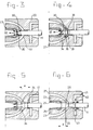
- Figure 3 shows a first intermediate position in which the contact has just been broken and an arc 30 has formed between the moving contact fingers 25 and fixed contact pin 11. Due to the energy released in the vicinity of the arc 30, the gas present in the arc area covered by the arc 30, which is preferably an extinguishing gas, such as SF 6 , is heated in that area, this increase in temperature on either side of the arc 30 resulting in an increase in pressure. On the inside of the arc, this increase in pressure acts in the direction of arrow 32, towards the left, between the contact fingers 25.
- an extinguishing gas such as SF 6
- this extinguishing is deliberately delayed by ensuring that the fixed contact pin 11 and the moving contact fingers 25 have to be pulled apart by a distance d of approximately 15 to 19 mm before contact pin 11 opens the opening 40 of the pressure-chamber outlet 27. It is thus possible to ensure that before any attempt is made to extinguish the arc, on the one hand, the arc 30 is of greater length, making the arc relatively weaker and easier to extinguish, and, on the other hand, at least if the pressure chamber 28 or pressure area 28 arc placed under increased pressure while the contacts are moving apart, the pressure available in the pressure chamber 28 for extinguishing, also known as puffing, is higher or is built up/increased further.
- Figure 4 shows a state which follows Figure 3 and in which the distance between the fixed contact 11 and the moving contact 24, 25 is increased further, and the arc is not, or is not yet, subject to a current zero crossing.
- the arc 30, as in the position illustrated in Figure 3 will increase the pressure, on both sides of the arc, of the gas which is situated in the arc area.
- this pressure increase will still be acting in the direction of arrow 32, between the contact fingers 25, and on the outside of the arc, the pressure increase will be acting in the direction of arrow 33, i.e. directed into the pressure-chamber outlet 27.
- an extinguishing-gas pressure directed as shown by arrow 34 will be acting from the pressure chamber 28 and the pressure-chamber outlet 27, which pressure will be balanced by the arc pressure 33 in the vicinity of a front which is diagrammatically illustrated by line 35.
- the arc thus prevents a gas stream which would extinguish the arc 30 from moving out of the pressure chamber 28 and the pressure-chamber outlet 27.
- An extinguishing or puffing action will only be able to take place as soon as the arc 30 becomes weaker as a result of the approach and possibly also passage of a current zero crossing, a position which is illustrated in Figure 5.
- the energy of the arc and, consequently, the resultant pressure increase will decrease, so that the pressure 34 from the pressure chamber 28 and pressure-chamber outlet 27 ( Figure 4) begins to overcome or over-compensate the pressure 33 generated by the arc energy ( Figure 4), with the result that the gas which is present in the pressure chamber 28 and pressure-chamber outlet 27 can actually begin to act on the (weaker) arc in order to extinguish or puff out this arc.
- the pressure-chamber pressure 34 will initially also be able to escape between the contact fingers 25, at least in the exemplary embodiment illustrated.
- this distance c approximately corresponds to the distance which is to be covered by the moveable contact, while the contacts arc moving apart, during half an oscillation period (i.e. during a period 1/2f, where f is the frequency in Hz).
- the ventilation system 42 comprises one or more radial, circular slots 43, the inlet sides of which open out onto a widening section of the contact passage 26.
- An annular pattern of bores 45 (of which only one is shown), which provides the radial annular slot 43 with outlets which open out at the right-hand end, is arranged in the right-hand end side of the main sleeve part 22.
- a piston 50 which can move together with the drive rod 6 is mounted on the assembly comprising rod 6 and drive rod 7, in particular in the vicinity of the transition between the rod 6 and the drive rod 7.
- This moveable piston 50 can be moved to and fro through the abovementioned fixed cylinder 18.
- the fixed cylinder 18, the fixed piston 19, the drive rod 7 and the moveable piston 50 together delimit the so-called intermediate chamber 51.
- intermediate chamber 51 Via a passage 70 in the wall of the drive rod 7, the interior 71 of the drive rod 7 and passages 53, intermediate chamber 51 is in communication with the area in the vicinity of the contact fingers 25, where the arc may form.
- the action of the pressure which is denoted by 32 in Figures 3 and 4 may extend all the way into the intermediate chamber 51.
- valve 72 which is arranged therein and allows passage in only one direction, can flow from intermediate chamber 51 into pressure chamber 28, so that the pressure in the pressure chamber 28 is also increased.
- valve 72 the most important role of valve 72 is to create a closeable pressuring channel, via which, when the contact closes again, the pressure chamber 28 can be filled with fresh gas as a result of the excess pressure which then arises in intermediate chamber 51 compared to that in pressure chamber 28.
- valve 60 is designed in such a manner that it is slightly open in its neutral position, i.e. in the contact state of the contacts. If an excess pressure were to develop in the intermediate chamber 51 as a result of the pressure generated by the arc energy, the valve 60 will close, in order to prevent this pressure from subsiding.
- the fixed cylinder 18 is designed to be open at its left-hand end, or is at least provided at this end with a feature allowing flow through the housing. In the exemplary embodiment illustrated in Figure 1 and Figure 2, this is achieved by means of passages 54 in the fixed cylinder 18 which lead towards the interior of the housing 1, 2, 3.
- the contacts can be pulled apart, for example, by means of a preloading mechanism (not shown) which acts on pull rod 6 and, in the "on state" illustrated in Figure 1, is under a prestress which tends to seek to drive the contacts further apart.
- a preloading mechanism (not shown) which acts on pull rod 6 and, in the "on state" illustrated in Figure 1, is under a prestress which tends to seek to drive the contacts further apart.
- the stressing mechanism will also be prestressed in the "off state" which is shown in Figure 2.
- the pistons 50 and 19 are provided with seals 80, 81.
Landscapes
- Circuit Breakers (AREA)
Applications Claiming Priority (2)
| Application Number | Priority Date | Filing Date | Title |
|---|---|---|---|
| NL1007753A NL1007753C2 (nl) | 1997-12-09 | 1997-12-09 | Werkwijze voor het middels een gasstroom doven van een lichtboog bij een vermogens-schakelaar alsmede vermogens-schakelaar. |
| NL1007753 | 1997-12-09 |
Publications (1)
| Publication Number | Publication Date |
|---|---|
| EP0921549A1 true EP0921549A1 (fr) | 1999-06-09 |
Family
ID=19766158
Family Applications (1)
| Application Number | Title | Priority Date | Filing Date |
|---|---|---|---|
| EP98204190A Withdrawn EP0921549A1 (fr) | 1997-12-09 | 1998-12-09 | Procédé pour éteindre l'arc dans des disjoncteurs de puissance élevée par un courant de gaz, et disjoncteur de puissance élevée |
Country Status (2)
| Country | Link |
|---|---|
| EP (1) | EP0921549A1 (fr) |
| NL (1) | NL1007753C2 (fr) |
Cited By (1)
| Publication number | Priority date | Publication date | Assignee | Title |
|---|---|---|---|---|
| JP2012094455A (ja) * | 2010-10-28 | 2012-05-17 | Toshiba Corp | ガス遮断器 |
Citations (3)
| Publication number | Priority date | Publication date | Assignee | Title |
|---|---|---|---|---|
| US3659065A (en) * | 1970-03-06 | 1972-04-25 | Westinghouse Electric Corp | Fluid-blast circuit interrupter with delayed moving contact travel |
| US4182942A (en) * | 1976-05-04 | 1980-01-08 | Hitachi, Ltd. | Puffer-type gas-blast circuit breaker |
| EP0741399A1 (fr) * | 1995-05-04 | 1996-11-06 | ANSALDO INDUSTRIA S.p.A. | Interrupteur haute tension à gaz diélectrique du type à auto soufflage |
-
1997
- 1997-12-09 NL NL1007753A patent/NL1007753C2/nl not_active IP Right Cessation
-
1998
- 1998-12-09 EP EP98204190A patent/EP0921549A1/fr not_active Withdrawn
Patent Citations (3)
| Publication number | Priority date | Publication date | Assignee | Title |
|---|---|---|---|---|
| US3659065A (en) * | 1970-03-06 | 1972-04-25 | Westinghouse Electric Corp | Fluid-blast circuit interrupter with delayed moving contact travel |
| US4182942A (en) * | 1976-05-04 | 1980-01-08 | Hitachi, Ltd. | Puffer-type gas-blast circuit breaker |
| EP0741399A1 (fr) * | 1995-05-04 | 1996-11-06 | ANSALDO INDUSTRIA S.p.A. | Interrupteur haute tension à gaz diélectrique du type à auto soufflage |
Cited By (1)
| Publication number | Priority date | Publication date | Assignee | Title |
|---|---|---|---|---|
| JP2012094455A (ja) * | 2010-10-28 | 2012-05-17 | Toshiba Corp | ガス遮断器 |
Also Published As
| Publication number | Publication date |
|---|---|
| NL1007753C2 (nl) | 1999-06-23 |
Similar Documents
| Publication | Publication Date | Title |
|---|---|---|
| US4774388A (en) | Compressed dielectric gas circuit breaker | |
| JPH01258331A (ja) | 電気回路遮断器 | |
| JP2009094067A (ja) | 2つの圧縮容積を有している電力回路遮断器の電流遮断チャンバー | |
| US4041263A (en) | Electric circuit interrupter of the puffer type comprising a magnetically actuated piston | |
| EP0921549A1 (fr) | Procédé pour éteindre l'arc dans des disjoncteurs de puissance élevée par un courant de gaz, et disjoncteur de puissance élevée | |
| JP2009129867A (ja) | パッファ形ガス絶縁遮断器 | |
| WO2015102310A1 (fr) | Disjoncteur à gaz d'appareillage de commutation isolé par gaz | |
| JP2568304B2 (ja) | 自動吹付け式中電圧遮断器 | |
| CS229671B2 (en) | High voltage power circuit braker | |
| US4992634A (en) | Medium tension gas blast circuit breaker | |
| KR101386134B1 (ko) | 열팽창실 압력 조절형 복합 소호 가스차단기 | |
| US5084600A (en) | Gas-blast load-break switch | |
| US4105879A (en) | Magnetic puffer type gas circuit breaker | |
| JP2563855B2 (ja) | 高電圧回路遮断器 | |
| US5155313A (en) | Medium tension circuit-breaker | |
| JPS6352729B2 (fr) | ||
| RU2091891C1 (ru) | Высоковольтный газовый выключатель с автогенерацией дугогасящего потока | |
| KR100345691B1 (ko) | 복합 소호형 가스 차단기 | |
| JPS6224519A (ja) | ガスしや断器 | |
| SU1067545A1 (ru) | Высоковольтный газовый выключатель | |
| JPH09282982A (ja) | 同期式ガス開閉装置 | |
| RU2140684C1 (ru) | Дугогасительное устройство высоковольтного газонаполненного автокомпрессионного выключателя | |
| JP2701338B2 (ja) | パッファ形ガス遮断器 | |
| SU603017A1 (ru) | Жидкостной выключатель высокого напр жени | |
| JP2551124B2 (ja) | パッファ形ガス遮断器 |
Legal Events
| Date | Code | Title | Description |
|---|---|---|---|
| PUAI | Public reference made under article 153(3) epc to a published international application that has entered the european phase |
Free format text: ORIGINAL CODE: 0009012 |
|
| AK | Designated contracting states |
Kind code of ref document: A1 Designated state(s): AT CH DE FR LI NL SE |
|
| AX | Request for extension of the european patent |
Free format text: AL;LT;LV;MK;RO;SI |
|
| 17P | Request for examination filed |
Effective date: 19990906 |
|
| AKX | Designation fees paid |
Free format text: AT CH DE FR LI NL SE |
|
| 17Q | First examination report despatched |
Effective date: 20050224 |
|
| STAA | Information on the status of an ep patent application or granted ep patent |
Free format text: STATUS: THE APPLICATION IS DEEMED TO BE WITHDRAWN |
|
| 18D | Application deemed to be withdrawn |
Effective date: 20050907 |