EP0922585A2 - Verfahren zur Korrektur von Unregelmässigkeiten in der Dichte und Bildaufzeichnungsgerät mit diesem Verfahren - Google Patents
Verfahren zur Korrektur von Unregelmässigkeiten in der Dichte und Bildaufzeichnungsgerät mit diesem Verfahren Download PDFInfo
- Publication number
- EP0922585A2 EP0922585A2 EP98123282A EP98123282A EP0922585A2 EP 0922585 A2 EP0922585 A2 EP 0922585A2 EP 98123282 A EP98123282 A EP 98123282A EP 98123282 A EP98123282 A EP 98123282A EP 0922585 A2 EP0922585 A2 EP 0922585A2
- Authority
- EP
- European Patent Office
- Prior art keywords
- correction
- gradation
- image
- values
- printing
- Prior art date
- Legal status (The legal status is an assumption and is not a legal conclusion. Google has not performed a legal analysis and makes no representation as to the accuracy of the status listed.)
- Granted
Links
- 238000000034 method Methods 0.000 title claims abstract description 46
- 238000012937 correction Methods 0.000 claims abstract description 106
- 238000012546 transfer Methods 0.000 claims description 13
- 238000003860 storage Methods 0.000 claims description 7
- 238000003702 image correction Methods 0.000 claims description 6
- 239000000463 material Substances 0.000 claims description 6
- 239000000049 pigment Substances 0.000 claims description 6
- 230000003287 optical effect Effects 0.000 claims description 3
- 239000002245 particle Substances 0.000 claims description 3
- 229920000642 polymer Polymers 0.000 claims description 3
- 230000035945 sensitivity Effects 0.000 abstract description 9
- 238000010438 heat treatment Methods 0.000 description 32
- 238000003825 pressing Methods 0.000 description 20
- 238000001514 detection method Methods 0.000 description 12
- 238000013459 approach Methods 0.000 description 4
- 230000001747 exhibiting effect Effects 0.000 description 4
- 238000012545 processing Methods 0.000 description 4
- 238000009826 distribution Methods 0.000 description 3
- 230000014509 gene expression Effects 0.000 description 3
- 238000006243 chemical reaction Methods 0.000 description 2
- 239000003086 colorant Substances 0.000 description 2
- 230000001788 irregular Effects 0.000 description 2
- 239000011159 matrix material Substances 0.000 description 2
- 239000002184 metal Substances 0.000 description 2
- 238000012935 Averaging Methods 0.000 description 1
- 210000000078 claw Anatomy 0.000 description 1
- 238000004891 communication Methods 0.000 description 1
- 239000000470 constituent Substances 0.000 description 1
- 238000005520 cutting process Methods 0.000 description 1
- 238000006073 displacement reaction Methods 0.000 description 1
- 239000000428 dust Substances 0.000 description 1
- 230000000694 effects Effects 0.000 description 1
- 230000006870 function Effects 0.000 description 1
- 238000003780 insertion Methods 0.000 description 1
- 230000037431 insertion Effects 0.000 description 1
- 238000002360 preparation method Methods 0.000 description 1
- 238000001454 recorded image Methods 0.000 description 1
- 238000000926 separation method Methods 0.000 description 1
- 239000000126 substance Substances 0.000 description 1
Images


Classifications
-
- B—PERFORMING OPERATIONS; TRANSPORTING
- B41—PRINTING; LINING MACHINES; TYPEWRITERS; STAMPS
- B41J—TYPEWRITERS; SELECTIVE PRINTING MECHANISMS, i.e. MECHANISMS PRINTING OTHERWISE THAN FROM A FORME; CORRECTION OF TYPOGRAPHICAL ERRORS
- B41J2/00—Typewriters or selective printing mechanisms characterised by the printing or marking process for which they are designed
- B41J2/315—Typewriters or selective printing mechanisms characterised by the printing or marking process for which they are designed characterised by selective application of heat to a heat sensitive printing or impression-transfer material
- B41J2/32—Typewriters or selective printing mechanisms characterised by the printing or marking process for which they are designed characterised by selective application of heat to a heat sensitive printing or impression-transfer material using thermal heads
- B41J2/35—Typewriters or selective printing mechanisms characterised by the printing or marking process for which they are designed characterised by selective application of heat to a heat sensitive printing or impression-transfer material using thermal heads providing current or voltage to the thermal head
- B41J2/355—Control circuits for heating-element selection
- B41J2/36—Print density control
Definitions
- the present invention relates to a technique for correcting recording density irregularity in image recording by using a line head.
- proof printing is performed and then final printing is performed after the finished state of the proofs is checked.
- final printing is performed after the finished state of the proofs is checked.
- the color proof is obtained by the steps of: thermally transferring an image to a receiver sheet by a thermal printer; and transferring the image formed on the receiver sheet to a sheet of paper.
- a specific example of the density irregularity correction method is the following method.
- an image is recorded on the basis of image data having a uniform gradation in the first main scanning direction of the line head.
- the thus recorded image is scanned by a densitometer such as a scanner, or the like, moving relatively in the subsidiary scanning direction of the line head to thereby detect printing density.
- the printing density obtained for each pixel is compared with the gradation value of the image data to thereby correct the gradation value of the image data.
- the printing-density value may vary in accordance with the individual sensitivity characteristic of the detection elements of the scanner.
- the sensitivity characteristic of the detection elements of the scanner is not uniform in the strict sense, so that printing densities to be detected as the same value originally are detected as different density values.
- the correction values which are set on the basis of the detected printing-density values become incorrect. There arises a problem that appropriate density irregularity correction cannot be made.
- the present invention is designed to provide density irregularity correction methods for correcting density irregularity accurately without influence of individual sensitivity characteristic peculiar to a scanner of an image recording apparatus.
- a method for correcting density irregularity in image recording using a line head by comprising the steps of: printing a belt-like pattern at a predetermined-gradation value in the first main scanning direction of the line head; relatively moving a line sensor along the first main scanning direction of the line head while aligning a second main scanning direction of the line sensor, which is corresponding to a scanning direction of said line sensor, with the subsidiary scanning direction of the line head to thereby detect printing density of the belt-like pattern; obtaining a correction condition for each pixel position on the basis of the detected printing-density value and the predetermined-gradation value; and correcting image data for image recording on the basis of the correction condition.
- the belt-like pattern includes a plurality of belt-like pattern portions printed at least two gradation values selected in the proximity of the predetermined-gradation value; and averages of printing-density values are obtained for the plurality of belt-like pattern portions respectively and the correction condition is set on the basis of the change ratios of the obtained averages of printing-density values to the gradation values of the belt-like pattern portions.
- a correction condition is set on the basis of the ratio of the difference between averages of printing-density values to the difference between the gradation values.
- the distribution of printing-density values for the gradation values is subjected to linear approximation, or the like, to obtain change ratios, so that correction conditions are set on the basis of the change ratio.
- the belt-like pattern includes first and second belt-like pattern portions which are printed at a first gradation value as the predetermined-gradation value and at a second gradation value near to the first gradation value, respectively; and averages of printing-density values are obtained for the first and second belt-like pattern portions respectively and the correction condition is set on the basis of the ratio of the difference between the obtained averages to the difference between the first and second gradation values.
- the predetermined-gradation value is any one of gradation values obtained by division of a gradation range up to the maximum gradation value into a plurality of equal stages; and correction conditions for all gradations are set by interpolation on the basis of individual correction conditions set for the respective stages.
- a range of from 0 to 255 is substantially divided into four equal parts so that five gradation values of 0, 64, 128, 192 and 255 are set.
- the values of 0 and 255 are not corrected and correction conditions for the gradation values of 64, 128 and 192 are obtained.
- Correction conditions for gradation values of 0 to 255 are set approximately by interpolation on the basis of the obtained individual correction conditions for the gradation values of 64, 128 and 192.
- an image recording apparatus comprising a correction value table storage portion for storing a correction value table for gradation value correction determined on the basis of printing-density values of image patterns printed, an image memory for storing image data corrected on the basis of the correction value table, and an image correction control portion for controlling correction of image data, characterized in that density correction data obtained by a method such as will be shown in this invention are stored in the correction value table storage portion.
- an image is recorded, by a thermal head, on a thermal transfer recording material having a substantially transparent heat-sensitive ink layer, the ink layer containing 30 to 70 parts by weight of pigment and 25 to 60 parts by weight of amorphous organic high-molecular polymer having a softening point of from 40°C to 150°C, the ink layer having a thickness of from 0.2 ⁇ m to 1.0 ⁇ m, 70% or more of the pigments contained in the heat-sensitive ink layer having particle sizes not larger than 1.0 ⁇ m, optical reflection density of a transfer image being not lower than 1.0 when the thermal transfer recording material is formed on a white support.
- FIG. 1 conceptually shows the main configuration of an image recording apparatus according to a mode for carrying out the present invention
- Fig. 2 is an explanatory view of the image recording apparatus depicted in Fig. 1 in the case where a printing operation is carried out
- Fig. 3 is an explanatory view of the image recording apparatus depicted in Fig. 1 in the case where 3 receiver sheet is ejected.
- This image recording apparatus 10 (hereinafter referred to as “recording apparatus 10") is configured as a recording apparatus with a laminator in which a pair of pressing/heating rollers are provided in a sheet carrying path of the recording apparatus.
- the laminator-including recording apparatus 10 comprises as main constituent members: a platen 601; a thermal head 61 which is a line head having heating elements disposed in opposition to the platen 601; an ink ribbon 64 put between the platen 601 and the thermal head 61 so as to be fed with advance of printing; a receiver sheet supply roll 6320 wound with a receiver sheet 632; a paper supply cassette 6310 containing sheets of paper 631; an ejection tray 6314 for ejecting a sheet of paper 631 after transferring an image to the sheet of paper 631; a withdrawal tray 6326 for withdrawing the receiver sheet 632 after transferring an image to a sheet of paper 631; a pair of pressing/heating rollers 603; and a pair of releasing rollers 602.
- a metal plate 6311 urged upward by a spring 6312 is provided in the paper supply cassette 6310 so that the metal plate 6311 urges sheets of paper 631 upward to press the sheets of paper 631 against a pickup roller 604.
- the uppermost sheet of paper 631 pressed against the pickup roller 604 is put between the pair of pressing/heating rollers 603 by a pair of paper supply rollers 605 when the pickup roller 604 rotates.
- the pair of pressing/heating rollers 603 are formed so as to be reversibly rotatable and movable both in a direction of approach of them to each other and in a direction of separation of them from each other.
- the pair of pressing/heating rollers 603 are designed so as to carry a combination of sheets (the receiver sheet 632 and a sheet of paper 631) while pressing and heating the combination of sheets in the condition that the pair of pressing/heating rollers 603 move to approach each other and to cancel the pressing/heating of the combination of sheets in the condition that the pair of pressing/heating rollers 603 move to separate from each other.
- a receiver sheet cutter 6325 is provided in a withdrawal path 6324 between the pair of pressing/heating rollers 603 and the withdrawal tray 6326 so that the receiver sheet cutter 6325 cuts the receiver sheet 632 which is carried to the withdrawal path 6324 after the completion of image transferring.
- the receiver sheet 632 is fed out of the supply roll 6320 by the quantity corresponding to one sheet of paper and then an image is printed by the thermal head 61 while the receiver sheet 632 is rewound on the supply roll 6320 in the direction of the arrows shown in Fig. 2.
- the pair of pressing/heating rollers 603 stand by in the condition that the pair of pressing/heating rollers 603 are moved so as to separate from each other, so that the pair of pressing/heating rollers 603 never touch the receiver sheet 632.
- this sequence is repeated by the number of times corresponding to the number of colors.
- the receiver sheet 632 is a thermal transfer recording material having a substantially transparent heat-sensitive ink layer ,which contains 30 to 70 parts by weight of pigment and 25 to 60 parts by weight of amorphous organic high-molecular polymer having a softening point of from 40°C to 150°C , which has a thickness of from 0.2 ⁇ m to 1.0 ⁇ m, in which 70 % or more of pigments have particle sizes not larger than 1.0 ⁇ m, and having optical reflection density of a transfer image being not lower than 1.0 when the thermal transfer recording material is formed on a white support.
- the receiver sheet 632 having the image printed thereon is fed out again by the quantity corresponding to one sheet of paper so that the forward end portion of the receiver sheet 632 is disposed in a neighbor of the insertion position between the pair of pressing/heating rollers 603 at the time of image recording.
- a sheet of paper 631 is pulled out from the paper supply cassette 6310 by the pickup roller 604.
- the pair of pressing/heating rollers 603 are moved to approach each other so that the combination of the receiver sheet 632 and the sheet of paper 631 is carried upward in Fig. 1 while both the receiver sheet 632 and the sheet of paper 631 are pressed and heated simultaneously.
- the forward end of the sheet of paper 631 which does not adhere to the receiver sheet 632 is released by the releasing rollers 602.
- the sheet of paper 631 thus released from the receiver sheet 632 is ejected to the ejection tray 6314 by a pair of carrying rollers 606 after releasing.
- the forward end of a releasing claw 65 is inserted into between the receiver sheet 632 and the sheet of paper 631, the sheet of paper 631 can be released more securely.
- the pair of pressing/heating rollers 603 separate from each other to return to standby positions.
- the receiver sheet 632 is fed out so that a portion of the receiver sheet 632 from which an image has been transferred to the sheet of paper 631 comes to the position of the receiver cutter 6325 as shown in Fig. 3.
- the image-transferred portion is cut and withdrawn to the withdrawal tray 6326.
- the step of feeding out the receiver sheet 632 for the withdrawal serves also as the step of feeding out the receiver sheet 632 for preparation for next printing.
- configuration may be made so that the rear heat roller (in the left in the drawings) does not separate.
- a portion of the receiver sheet to be subjected to next printing is heated in advance, so that substances in the recording surface of the receiver sheet are stabilized. This brings an effect that recording sensitivity is stabilized.
- a non-transferred portion of the receiver sheet 632 can be obtained by the steps of: feeding out the receiver sheet 632 to eject a printed portion of the receiver sheet 632 to the withdrawal tray 6326; and cutting the printed portion of the receiver sheet 632 by the receiver sheet cutter 6325 to eject the non-transferred portion of the receiver sheet 632 to the withdrawal tray 6326.
- a recording portion 20 of the recording apparatus 10 will be described below with reference to Fig. 4.
- the columnar platen 601 provided in opposition to the thermal head 61 rotates, for example, counterclockwise to carry the receiver sheet 632 and presses both the thermal head 61 and the ink ribbon 64 by a predetermined pressure toward the thermal head 61, so that the ink ribbon 64 is wound up on the take-up side 641 through a guide roller 643.
- the receiver sheet 632 to which an image is thermally transferred through the ink ribbon 64 by heating resistors of the thermal head 61, is driven to be carried by a pair of rolls 607 and 608 via the platen 601.
- heating resistors for recording a one-line's portion of the image on the receiver sheet 632 are arrayed in one direction (perpendicular to a plane forming Fig. 4).
- the platen 601 rotates at a predetermined image-transfer speed while holding the receiver sheet 632 in a predetermined position to thereby carry the receiver sheet 632 in a direction substantially perpendicular to the direction of extension of glaze 61a of the thermal head (that is, in a direction of the arrow b in Fig. 4).
- a predetermined transfer start position of the receiver sheet 632 is carried to a position opposite to the glaze 61a and then the receiver sheet 632 is carried in the direction of the arrow b by the platen 601 while being aligned with the ink ribbon 64 (in accordance with each of colors Y, M, C and K in the case of a color image).
- the respective heating resistors of the glaze 61a are heated in accordance with image data of the recording image to thereby perform transfer recording to the receiver sheet 632.
- an image corresponding to the recording image is transferred to the receiver sheet 632.
- monochromatic images are transferred, for example, in order of Y, M, C and K, to the receiver sheet 632 so as to be superposed on one another.
- an image data correction control system for correcting image data of the recording image in the recording apparatus includes: an image correction control portion 1 for correcting input image data to generate corrected image data; a correction value table storage portion 2 for storing a correction value table for correcting image data; and an image memory 3 for storing the corrected image data.
- a method for correcting image data by the aforementioned image data correction control system will be described below with reference to a flow chart shown in Fig. 5.
- a density irregularity correction method in this mode is schematically to detect printing-density values of image patterns recorded at predetermined-gradation values to thereby determine values for correcting the gradation values of image data on the basis of the ratios of the obtained printing-density values to the gradation values. The detailed procedure will be described below.
- step S1 belt-like image patterns shown in Fig. 6 are recorded at predetermined-gradation values respectively by the recording portion 20.
- a predetermined gradation width for example, 5 gradations
- the present invention is not limited thereto but may be applied to the case where the number of stages is reduced for simplification of calculation or to the case where the number of stages is increased for improvement of accuracy in setting the correction values.
- the predetermined gradation width is selected to be 5 gradations, this value may be preferably set so as to be suitably changed in accordance with image data used. Further, either addition or subtraction of a predetermined gradation width may be set so that the two gradation values of a predetermined-gradation value and a gradation value obtained by addition or subtraction are used as one group for performing processing after that.
- a plurality of gradation values (for example, five gradation values in total, that is, a predetermined-gradation value Di, Di ⁇ 5, Di ⁇ 10) with a sample gradation value as its center may be set so that the plurality of gradation values are used as one group for performing processing.
- the aforementioned values are preferably determined on the basis of balance between correction accuracy and processing time.
- FIG. 6 and (c) of Fig. 6 show results of recording corresponding to sample gradation values D2 and D3 respectively.
- printing density in each of belt-like pattern portion is ideally uniform and equivalent to the set gradation value as the gradation value of the image data
- the actual recording results may show that the printing density is often shifted from density corresponding to the set gradation value or varies in accordance with the recording position to thereby bring density irregularity in the first main scanning direction.
- each of the printing-density values La(H), Lb(H) and Lc(H) is obtained by averaging printing-density values (printing-density values in the same H position) against several pixels in the belt width of each belt-like pattern.
- printing-density values printing-density values in the same H position
- printing-density values can be detected accurately even in the case where, for example, white missing dots or black dots are printed on the belt-like pattern or dust, or the like, is deposited on the belt-like pattern.
- a resolution changing process can be performed by a known method. Further, because it is difficult to dispose the scanner in a perpendicular position strictly, a position detection pattern may be preferably disposed in the printing image in advance so that this pattern is used as a reference for performing image rotation and the resolution changing process.
- the printing-density values La(H), Lb(H) and Lc(H) obtained by scanning with the scanner 71 exhibit density distributions as shown in Fig. 8.
- the printing-density values La(H), Lb(H) and Lc(H) are displaced from the set gradation values Da1, Db1 and Dc1 respectively in terms of absolute values.
- the quantity of displacement varies in accordance with each pixel and in accordance with each set gradation value. Accordingly, correction processes are required in accordance with pixels and gradations in order to obtain uniform density corresponding to the set gradation value.
- step S3 averages LaAV, LbAV and LcAV of the printing-density values La(H), Lb(H) and Lc(H) obtained by scanning with the scanner are obtained against all pixels.
- the correction coefficients Ri which are the ratios of gradation values to printing-density values in neighbors of sample gradation values, are calculated by the expression (1).
- Ri (Dci - Dai)/(LcAV - LaAV)
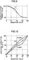
- Fig. 9 shows the relation of the density value detected by the scanner with the set gradation value.
- the correction coefficient Ri expresses the change of the density value detected by the scanner in a neighbor of each sample gradation value, that is, the correction coefficient Ri expresses an inclination 91.
- step S5 gradation correction values Xi(H) for correcting printing-density values appropriately are calculated by the expression (2) with Ri obtained in the step S4.
- Xi(H) Di - ⁇ LbAV - Lb(H) ⁇ Ri
- gradation correction values can be determined accurately in the aforementioned manner even in the case where, for example, a different type of scanner is used or a scanner irregular in sensitivity characteristic in the second main scanning direction is used.
- gradation correction values Xi(H) corresponding to all sample gradation values Di are calculated, gradation correction values corresponding to respective sample gradation values Di are obtained for all pixels as shown in Fig. 10.
- gradation correction values corresponding to sample gradation values D0 and D4 are set to be 0 and 255, respectively, for all pixels.
- step S8 gradation correction values x(H) for all gradations are obtained approximately on the basis of the discrete gradation correction values Xi(H) obtained in the step S5 correspondingly to respective sample gradation values.
- gradation correction values can be obtained with practically sufficient accuracy, so that the process for calculating gradation correction values can be simplified.
- gradation correction values as integers because the gradation correction values are set as gradation values of an image directly. Examples of means for converting a number as an integer are the following two methods.
- a first method is a method for rounding a decimal to the nearest integer number simply.
- a second method is a method for performing conversion on the basis of a probability means.
- a gradation correction value inclusive of decimal places is 128.5
- the correction value is regarded as 128 in the case where the line position in the subsidiary scanning direction is an even-numbered line position
- the correction value is regarded as 129 in the case where the line position in the subsidiary scanning direction is an odd-numbered line position.
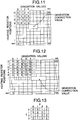
- a specific method used for this process is as follows. First, all gradation correction values inclusive of decimal places are quadrupled and decimal places of the quadrupled correction values are cut. Accordingly, the gradation range of gradation correction values of from 0 to 255 are extended to a gradation range of from 0 to 1020. That is, a correction value table shown in Fig. 12 is generated so that first, printing gradation data of gradation correction values of from 0 to 255 are converted into gradation data of from 0 to 1020.
- values of 0 to 3 determined on the basis of the printing position are used as addition values which are added to data of 0 to 1020, so that the gradation correction values are converted into values in a gradation range of from 0 to 1023.
- each of the values is divided by 4 and decimal places are cut.
- the aforementioned addition values may be determined by use of a matrix shown in Fig. 13.
- gradation correction values are converted into integers.
- p shown in Fig. 13 corresponds to the remainder when the heater position H is divided by 4
- q corresponds to the remainder when the subsidiary scanning line position is divided by 4.
- the conversion of the correction value into an integer in the aforementioned manner is as follows. First, 128.3 is quadrupled and decimal places of the resulting number are cut, so that the correction value is converted into 513. Then, an addition value in accordance with the printing position with reference to Fig. 13 is added to the converted correction value. After addition, the resulting number is divided by 4 and decimal places are cut.
- the correction value is converted into 128 in the printing position exhibiting the addition value of 0
- the correction value is converted into 128 in the printing position exhibiting the addition value of 1
- the correction value is converted into 128 in the printing position exhibiting the addition value of 2
- the correction value is converted into 129 in the printing position exhibiting the addition value of 3. Because the probabilities that addition values of 0 to 3 will appear are equal, the correction value of 128.3 is converted into 128 in a probability of 3/4 and into 129 in a probability of 1/4.
- step S10 image data from the outside are inputted into the image correction control portion 1.
- image data stored in a recording medium such as a photomagnetic disk, a floppy disk, or the like, are read out or image data are taken in by communication with an external apparatus, so that the image data are inputted.
- step S11 gradation correction values corresponding to pixel and gradation values of the input image data are read with reference to the correction value table stored in the correction value table storage portion 2 with respect to the pixel values of the input image data.
- the gradation correction values are supplied to the image memory 3 so that corrected image data are constructed on the image memory 3.
- step S12 the corrected image data stored in the image memory 3 are supplied to the thermal head 61 in accordance with a recording instruction of the image correction control portion 1, so that the corrected image data are formed on a heat-sensitive film A.
- the recording image constituted by the thus formed corrected image data is obtained as a high-quality image free from density irregularity because density irregularity in the first main scanning direction of the thermal head 61 is corrected appropriately with respect to all pixels and all gradation values.
- the scanner is moved in the first main scanning direction of the thermal head to thereby detect printing density recorded at a predetermined-gradation value. Accordingly, density irregularity in the second main scanning direction can be measured in the same condition, so that printing density can be detected accurately. Further, density values detected by a plurality of detection elements contained in the scanner are averaged to obtain a printing-density value. Accordingly, detection accuracy can be improved more greatly. Accordingly, even in the case where sensitivity characteristic in the second main scanning direction of the scanner is irregular or the scanner is not calibrated, density irregularity appearing in the first main scanning direction of the thermal head can be corrected accurately.
- printing densities of belt-like patterns, or the like, recorded at predetermined gradations are detected while a line sensor is relatively moved along the first main scanning direction of a line head.
- gradation correction values can be stably detected without influence of individual characteristics of different line sensors, or without influence of sensitivity characteristic depending on different detection elements of a line sensor. Accordingly, density irregularity can be corrected accurately.
Landscapes
- Electronic Switches (AREA)
- Facsimile Image Signal Circuits (AREA)
- Fax Reproducing Arrangements (AREA)
- Record Information Processing For Printing (AREA)
- Color, Gradation (AREA)
- Ink Jet (AREA)
Applications Claiming Priority (2)
| Application Number | Priority Date | Filing Date | Title |
|---|---|---|---|
| JP33719097A JP3703061B2 (ja) | 1997-12-08 | 1997-12-08 | 濃度ムラ補正方法及び該方法を用いた画像記録装置 |
| JP33719097 | 1997-12-08 |
Publications (3)
| Publication Number | Publication Date |
|---|---|
| EP0922585A2 true EP0922585A2 (de) | 1999-06-16 |
| EP0922585A3 EP0922585A3 (de) | 2000-03-15 |
| EP0922585B1 EP0922585B1 (de) | 2004-07-07 |
Family
ID=18306300
Family Applications (1)
| Application Number | Title | Priority Date | Filing Date |
|---|---|---|---|
| EP98123282A Expired - Lifetime EP0922585B1 (de) | 1997-12-08 | 1998-12-07 | Verfahren zur Korrektur von Unregelmässigkeiten in der Dichte und Bildaufzeichnungsgerät mit diesem Verfahren |
Country Status (4)
| Country | Link |
|---|---|
| US (1) | US6313857B1 (de) |
| EP (1) | EP0922585B1 (de) |
| JP (1) | JP3703061B2 (de) |
| DE (1) | DE69824941T2 (de) |
Cited By (4)
| Publication number | Priority date | Publication date | Assignee | Title |
|---|---|---|---|---|
| EP1457345A1 (de) * | 2003-03-12 | 2004-09-15 | Agfa-Gevaert | Thermokopfdrucker und Verfahren zum Drucken auf thermographischen Aufzeichnungsmaterialien |
| US7139010B2 (en) | 2003-03-12 | 2006-11-21 | Agfa Gevaert | Thermal head printer and process for printing substantially light-insensitive recording materials |
| EP1626566A4 (de) * | 2003-05-08 | 2007-08-15 | Seiko Epson Corp | Bildbearbeitung zum exprimieren einer gradation |
| US9981481B2 (en) | 2014-09-29 | 2018-05-29 | Citizen Watch Co., Ltd. | Thermal transfer printer and printing method using same |
Families Citing this family (9)
| Publication number | Priority date | Publication date | Assignee | Title |
|---|---|---|---|---|
| JP2002142113A (ja) * | 2000-10-30 | 2002-05-17 | Canon Inc | 画像処理装置、画像処理システム、画像処理方法、及び記憶媒体 |
| JP2002264412A (ja) * | 2001-03-14 | 2002-09-18 | Canon Inc | 画像処理方法、プログラムおよび画像処理装置 |
| US7661787B2 (en) | 2004-02-13 | 2010-02-16 | Seiko Epson Corporation | Printing method, computer-readable medium, printing apparatus, method of manufacturing printing apparatus, printing system, and correction pattern |
| JP2007151075A (ja) * | 2005-10-31 | 2007-06-14 | Seiko Epson Corp | 印刷装置、印刷方法、画像処理装置、画像処理方法、印刷プログラム、画像処理プログラム、及び記録媒体 |
| JP5996469B2 (ja) * | 2013-03-28 | 2016-09-21 | シチズンホールディングス株式会社 | プリンタ |
| JP6070610B2 (ja) * | 2014-03-17 | 2017-02-01 | 株式会社Jvcケンウッド | 階調データ生成装置及び方法 |
| CN108215516B (zh) * | 2016-12-22 | 2021-05-11 | 佳能精技立志凯株式会社 | 图像形成装置、记录介质以及图像形成系统 |
| KR102794857B1 (ko) * | 2018-09-11 | 2025-04-10 | 소니그룹주식회사 | 묘화 방법, 감열성 기록 매체, 및 묘화 장치 |
| CN113344819A (zh) * | 2021-06-24 | 2021-09-03 | 浙江汇诚汇捷影像数码科技有限公司 | 一种热敏胶片成像的灰阶曲线调整方法及系统 |
Family Cites Families (10)
| Publication number | Priority date | Publication date | Assignee | Title |
|---|---|---|---|---|
| JP2854318B2 (ja) | 1989-04-28 | 1999-02-03 | キヤノン株式会社 | 画像記録装置 |
| US5202773A (en) | 1989-12-22 | 1993-04-13 | Fuji Xerox Co., Ltd. | Multiple value image input device with chromatic gradation correction |
| JPH0832462B2 (ja) | 1990-02-27 | 1996-03-29 | 三菱電機株式会社 | 階調記録プリンタ |
| US5353052A (en) | 1990-05-11 | 1994-10-04 | Canon Kabushiki Kaisha | Apparatus for producing unevenness correction data |
| JP3274200B2 (ja) | 1992-12-28 | 2002-04-15 | キヤノン株式会社 | 画像形成方法及び装置 |
| DE69603657T2 (de) | 1995-05-15 | 1999-12-02 | Fuji Photo Film Co., Ltd. | Bildaufzeichnungssystem und Bildempfangsblatt |
| JPH09234899A (ja) * | 1996-02-29 | 1997-09-09 | Fuji Photo Film Co Ltd | 感熱記録装置 |
| EP0799706B1 (de) * | 1996-04-01 | 2000-06-28 | Fuji Photo Film Co., Ltd. | Wärmeaufzeichnungsverfahren und Vorrichtung |
| JPH1051635A (ja) * | 1996-07-31 | 1998-02-20 | Fuji Photo Film Co Ltd | 画像記録装置 |
| JPH10286986A (ja) * | 1997-04-14 | 1998-10-27 | Fuji Photo Film Co Ltd | 濃度ムラ補正方法 |
-
1997
- 1997-12-08 JP JP33719097A patent/JP3703061B2/ja not_active Expired - Fee Related
-
1998
- 1998-12-07 US US09/206,288 patent/US6313857B1/en not_active Expired - Lifetime
- 1998-12-07 DE DE69824941T patent/DE69824941T2/de not_active Expired - Lifetime
- 1998-12-07 EP EP98123282A patent/EP0922585B1/de not_active Expired - Lifetime
Cited By (5)
| Publication number | Priority date | Publication date | Assignee | Title |
|---|---|---|---|---|
| EP1457345A1 (de) * | 2003-03-12 | 2004-09-15 | Agfa-Gevaert | Thermokopfdrucker und Verfahren zum Drucken auf thermographischen Aufzeichnungsmaterialien |
| US7139010B2 (en) | 2003-03-12 | 2006-11-21 | Agfa Gevaert | Thermal head printer and process for printing substantially light-insensitive recording materials |
| EP1626566A4 (de) * | 2003-05-08 | 2007-08-15 | Seiko Epson Corp | Bildbearbeitung zum exprimieren einer gradation |
| US9981481B2 (en) | 2014-09-29 | 2018-05-29 | Citizen Watch Co., Ltd. | Thermal transfer printer and printing method using same |
| EP3202579A4 (de) * | 2014-09-29 | 2018-05-30 | Citizen Watch Co., Ltd. | Thermotransferdrucker und druckverfahren damit |
Also Published As
| Publication number | Publication date |
|---|---|
| JP3703061B2 (ja) | 2005-10-05 |
| US6313857B1 (en) | 2001-11-06 |
| JPH11170589A (ja) | 1999-06-29 |
| DE69824941D1 (de) | 2004-08-12 |
| DE69824941T2 (de) | 2004-12-16 |
| EP0922585A3 (de) | 2000-03-15 |
| EP0922585B1 (de) | 2004-07-07 |
Similar Documents
| Publication | Publication Date | Title |
|---|---|---|
| EP0922585B1 (de) | Verfahren zur Korrektur von Unregelmässigkeiten in der Dichte und Bildaufzeichnungsgerät mit diesem Verfahren | |
| US5006866A (en) | Thermal printing apparatus responsive to estimated stored heat of the heating element | |
| EP1336500B1 (de) | Bilderzeugungsgerät | |
| US20120327151A1 (en) | Inkjet recording apparatus and inkjet recording method | |
| US7380898B2 (en) | Calibration method for a printer | |
| JP2010105359A (ja) | 画像記録装置 | |
| US6801234B2 (en) | Color thermal printer | |
| US20060158505A1 (en) | Method and device for adjusting alignment of image forming apparatus | |
| JP2009148954A (ja) | 記録装置及び搬送制御方法 | |
| JP2002269543A (ja) | 濃度測定方法及び画像形成装置 | |
| EP0451321B1 (de) | Einrichtung zum Steuern der Papierlage in einem Registrierapparat | |
| US4816902A (en) | Method for continuously preparing films for use in making printing plates for off set lithography and image-forming apparatus for preparing the films | |
| US8136910B2 (en) | Calibration method for a printer | |
| US8705138B2 (en) | Image forming apparatus including an image calibration system | |
| JP6018534B2 (ja) | カラー画像処理装置 | |
| JP4151953B2 (ja) | インクジェット記録装置および副走査送り量補正方法 | |
| JP2882646B2 (ja) | カラー画像記録装置 | |
| JPH04278383A (ja) | 画像形成装置 | |
| JP3359767B2 (ja) | 熱転写記録装置 | |
| JP2885799B2 (ja) | 画像処理装置 | |
| JPH02263680A (ja) | インクカセットおよび熱転写プリンタ | |
| US6704121B1 (en) | Image forming method and image forming apparatus | |
| JP2882661B2 (ja) | 画像記録装置 | |
| EP1223040A2 (de) | Thermodrucker | |
| JPH023327A (ja) | 画像記録装置 |
Legal Events
| Date | Code | Title | Description |
|---|---|---|---|
| PUAI | Public reference made under article 153(3) epc to a published international application that has entered the european phase |
Free format text: ORIGINAL CODE: 0009012 |
|
| AK | Designated contracting states |
Kind code of ref document: A2 Designated state(s): DE FR GB |
|
| AX | Request for extension of the european patent |
Free format text: AL;LT;LV;MK;RO;SI |
|
| PUAL | Search report despatched |
Free format text: ORIGINAL CODE: 0009013 |
|
| AK | Designated contracting states |
Kind code of ref document: A3 Designated state(s): AT BE CH CY DE DK ES FI FR GB GR IE IT LI LU MC NL PT SE |
|
| AX | Request for extension of the european patent |
Free format text: AL;LT;LV;MK;RO;SI |
|
| 17P | Request for examination filed |
Effective date: 20000503 |
|
| AKX | Designation fees paid |
Free format text: DE FR GB |
|
| 17Q | First examination report despatched |
Effective date: 20020801 |
|
| GRAP | Despatch of communication of intention to grant a patent |
Free format text: ORIGINAL CODE: EPIDOSNIGR1 |
|
| GRAS | Grant fee paid |
Free format text: ORIGINAL CODE: EPIDOSNIGR3 |
|
| GRAA | (expected) grant |
Free format text: ORIGINAL CODE: 0009210 |
|
| AK | Designated contracting states |
Kind code of ref document: B1 Designated state(s): DE FR GB |
|
| REG | Reference to a national code |
Ref country code: GB Ref legal event code: FG4D |
|
| REF | Corresponds to: |
Ref document number: 69824941 Country of ref document: DE Date of ref document: 20040812 Kind code of ref document: P |
|
| ET | Fr: translation filed | ||
| PLBE | No opposition filed within time limit |
Free format text: ORIGINAL CODE: 0009261 |
|
| STAA | Information on the status of an ep patent application or granted ep patent |
Free format text: STATUS: NO OPPOSITION FILED WITHIN TIME LIMIT |
|
| 26N | No opposition filed |
Effective date: 20050408 |
|
| REG | Reference to a national code |
Ref country code: GB Ref legal event code: 732E |
|
| REG | Reference to a national code |
Ref country code: FR Ref legal event code: TP Ref country code: FR Ref legal event code: CD |
|
| REG | Reference to a national code |
Ref country code: FR Ref legal event code: PLFP Year of fee payment: 18 |
|
| REG | Reference to a national code |
Ref country code: FR Ref legal event code: PLFP Year of fee payment: 19 |
|
| REG | Reference to a national code |
Ref country code: DE Ref legal event code: R082 Ref document number: 69824941 Country of ref document: DE Representative=s name: KLUNKER IP PATENTANWAELTE PARTG MBB, DE |
|
| REG | Reference to a national code |
Ref country code: FR Ref legal event code: PLFP Year of fee payment: 20 |
|
| PGFP | Annual fee paid to national office [announced via postgrant information from national office to epo] |
Ref country code: DE Payment date: 20171129 Year of fee payment: 20 Ref country code: FR Payment date: 20171113 Year of fee payment: 20 |
|
| PGFP | Annual fee paid to national office [announced via postgrant information from national office to epo] |
Ref country code: GB Payment date: 20171206 Year of fee payment: 20 |
|
| REG | Reference to a national code |
Ref country code: DE Ref legal event code: R071 Ref document number: 69824941 Country of ref document: DE |
|
| REG | Reference to a national code |
Ref country code: GB Ref legal event code: PE20 Expiry date: 20181206 |
|
| PG25 | Lapsed in a contracting state [announced via postgrant information from national office to epo] |
Ref country code: GB Free format text: LAPSE BECAUSE OF EXPIRATION OF PROTECTION Effective date: 20181206 |