EP0922632A2 - Organe d'ancrage de siège pour aéronef - Google Patents
Organe d'ancrage de siège pour aéronef Download PDFInfo
- Publication number
- EP0922632A2 EP0922632A2 EP98204156A EP98204156A EP0922632A2 EP 0922632 A2 EP0922632 A2 EP 0922632A2 EP 98204156 A EP98204156 A EP 98204156A EP 98204156 A EP98204156 A EP 98204156A EP 0922632 A2 EP0922632 A2 EP 0922632A2
- Authority
- EP
- European Patent Office
- Prior art keywords
- seat track
- clip
- shaft
- extending
- floor
- Prior art date
- Legal status (The legal status is an assumption and is not a legal conclusion. Google has not performed a legal analysis and makes no representation as to the accuracy of the status listed.)
- Granted
Links
Images





Classifications
-
- F—MECHANICAL ENGINEERING; LIGHTING; HEATING; WEAPONS; BLASTING
- F16—ENGINEERING ELEMENTS AND UNITS; GENERAL MEASURES FOR PRODUCING AND MAINTAINING EFFECTIVE FUNCTIONING OF MACHINES OR INSTALLATIONS; THERMAL INSULATION IN GENERAL
- F16B—DEVICES FOR FASTENING OR SECURING CONSTRUCTIONAL ELEMENTS OR MACHINE PARTS TOGETHER, e.g. NAILS, BOLTS, CIRCLIPS, CLAMPS, CLIPS OR WEDGES; JOINTS OR JOINTING
- F16B21/00—Means for preventing relative axial movement of a pin, spigot, shaft or the like and a member surrounding it; Stud-and-socket releasable fastenings
- F16B21/02—Releasable fastening devices locking by rotation
-
- B—PERFORMING OPERATIONS; TRANSPORTING
- B60—VEHICLES IN GENERAL
- B60N—SEATS SPECIALLY ADAPTED FOR VEHICLES; VEHICLE PASSENGER ACCOMMODATION NOT OTHERWISE PROVIDED FOR
- B60N2/00—Seats specially adapted for vehicles; Arrangement or mounting of seats in vehicles
- B60N2/005—Arrangement or mounting of seats in vehicles, e.g. dismountable auxiliary seats
- B60N2/015—Attaching seats directly to vehicle chassis
-
- B—PERFORMING OPERATIONS; TRANSPORTING
- B64—AIRCRAFT; AVIATION; COSMONAUTICS
- B64C—AEROPLANES; HELICOPTERS
- B64C1/00—Fuselages; Constructional features common to fuselages, wings, stabilising surfaces or the like
- B64C1/18—Floors
-
- B—PERFORMING OPERATIONS; TRANSPORTING
- B64—AIRCRAFT; AVIATION; COSMONAUTICS
- B64D—EQUIPMENT FOR FITTING IN OR TO AIRCRAFT; FLIGHT SUITS; PARACHUTES; ARRANGEMENT OR MOUNTING OF POWER PLANTS OR PROPULSION TRANSMISSIONS IN AIRCRAFT
- B64D11/00—Passenger or crew accommodation; Flight-deck installations not otherwise provided for
- B64D11/06—Arrangements of seats, or adaptations or details specially adapted for aircraft seats
- B64D11/0696—Means for fastening seats to floors, e.g. to floor rails
-
- F—MECHANICAL ENGINEERING; LIGHTING; HEATING; WEAPONS; BLASTING
- F16—ENGINEERING ELEMENTS AND UNITS; GENERAL MEASURES FOR PRODUCING AND MAINTAINING EFFECTIVE FUNCTIONING OF MACHINES OR INSTALLATIONS; THERMAL INSULATION IN GENERAL
- F16B—DEVICES FOR FASTENING OR SECURING CONSTRUCTIONAL ELEMENTS OR MACHINE PARTS TOGETHER, e.g. NAILS, BOLTS, CIRCLIPS, CLAMPS, CLIPS OR WEDGES; JOINTS OR JOINTING
- F16B19/00—Bolts without screw-thread; Pins, including deformable elements; Rivets
- F16B19/002—Resiliently deformable pins
-
- F—MECHANICAL ENGINEERING; LIGHTING; HEATING; WEAPONS; BLASTING
- F16—ENGINEERING ELEMENTS AND UNITS; GENERAL MEASURES FOR PRODUCING AND MAINTAINING EFFECTIVE FUNCTIONING OF MACHINES OR INSTALLATIONS; THERMAL INSULATION IN GENERAL
- F16B—DEVICES FOR FASTENING OR SECURING CONSTRUCTIONAL ELEMENTS OR MACHINE PARTS TOGETHER, e.g. NAILS, BOLTS, CIRCLIPS, CLAMPS, CLIPS OR WEDGES; JOINTS OR JOINTING
- F16B19/00—Bolts without screw-thread; Pins, including deformable elements; Rivets
- F16B19/04—Rivets; Spigots or the like fastened by riveting
- F16B19/08—Hollow rivets; Multi-part rivets
- F16B19/10—Hollow rivets; Multi-part rivets fastened by expanding mechanically
- F16B19/1027—Multi-part rivets
-
- Y—GENERAL TAGGING OF NEW TECHNOLOGICAL DEVELOPMENTS; GENERAL TAGGING OF CROSS-SECTIONAL TECHNOLOGIES SPANNING OVER SEVERAL SECTIONS OF THE IPC; TECHNICAL SUBJECTS COVERED BY FORMER USPC CROSS-REFERENCE ART COLLECTIONS [XRACs] AND DIGESTS
- Y02—TECHNOLOGIES OR APPLICATIONS FOR MITIGATION OR ADAPTATION AGAINST CLIMATE CHANGE
- Y02T—CLIMATE CHANGE MITIGATION TECHNOLOGIES RELATED TO TRANSPORTATION
- Y02T50/00—Aeronautics or air transport
- Y02T50/40—Weight reduction
Definitions
- the present invention relates to an improved fastener assembly and, more particularly, a fastener assembly or mounting seat tracks and floor panels within an aircraft cabin with fewer parts and requiring reduced installation time.
- the seats are mounted to two underlying seat tracks. These seat tracks generally extend lengthwise along the passenger compartment of an aircraft such that two or more seats can be mounted thereto.
- the seat tracks are, in turn, securely mounted to the floor beams located within the undercarriage of the aircraft.
- the floor beams generally run perpendicular to the seat tracks, that is, the floor beams typically run laterally beneath the passenger compartment of an aircraft.
- the seat tracks and floor beams are usually made of a relatively strong metal or metal alloy in order to withstand the relatively high loading forces.
- the seat tracks are mounted to the floor beams using thousands of individual fasteners.
- a seat track is typically placed across the floor beams and is fastened thereto by means of the fasteners.
- the seat track is attached to each of the underlying floor beams by at least four fasteners, such as threaded fasteners or weldments.
- this installation method requires a large number of parts and increases the weight of the resulting aircraft, thereby increasing the overall production and operational costs.
- holes are generally drilled or otherwise formed in both the seat tracks and the floor beams in order to receive each of the fasteners, the structural integrity of the seat tracks and the floor beams is somewhat compromised.
- U.S. Patent No. 4,185,799 to Edward W. Richards, Jr. describes a fastener assembly for use in aircraft that disadvantageously employs a large number of parts.
- the fastener assembly of the Richards '799 patent includes a plurality of relatively small components cooperably attached with a series of screws, bolts, and rivets.
- U.S. Patent No. 4,936,527 to Frederick J. Gorges discloses a related assembly system for connecting an automobile seat and respective seat track with a multitude of rollers, levers, and joints.
- Modern commercial passenger aircraft also require a number of panels to be installed so as to form the floor, the galley, the lavatories, etc.
- floor panels are oftentimes connected to the seat tracks and, in turn, to the floor beams with a number of individual fasteners, such as threaded fasteners.
- individual fasteners such as threaded fasteners
- the interlocking assembly system of the present invention addresses many of the deficiencies associated with the conventional techniques for attaching seat tracks and panels, such as floor panels, within an aircraft cabin.
- the interlocking assembly system advantageously reduces the part count and the resulting installation time by providing clip fasteners for connecting the seat tracks to the floor beams.
- the seat tracks and associated clip fasteners of the present invention permit the seat tracks to be removed in a reasonably quick fashion.
- the interlocking assembly system does not require holes to be drilled or otherwise formed in the seat tracks and the floor beams, thereby maintaining the structural integrity of the seat tracks and the floor beams.
- the interlocking seat track assembly system includes the seat track, the floor beam and the clip for connecting the seat track to the underlying floor beam.
- the clip includes first and second clip members that cooperate to engage the opposed edges of the floor beam.
- Each clip member has a beam attachment portion, typically including an inward sill, for engaging the respective beam edge once the clip members have been slidably engaged.
- the first clip member includes an elongate tongue extending away from the respective beam attachment portion.
- the second clip member includes a pair of elongate rails that extend away from the respective beam attachment portion and are spaced apart to define a lengthwise extending channel that is sized to slidably receive the elongate tongue.
- the clip members can be secured by a fastener.
- the second clip member can include a tab defining a hole and extending away from the beam attachment portion in a direction opposite the rails.
- the elongate tongue of the first clip member also defines a hole positioned such that the holes of the first and second clip members are aligned once the elongate tongue is received within the lengthwise extending channel of the second clip member. Once aligned, a fastener can be inserted through the holes.
- the elongate rails of the second clip member also include lengthwise extending lips that engage corresponding tabs of the seat track in order to securely mount the seat track to the floor beam.
- the seat track generally has a U-shape so as to define an inner channel with respective inner and outer surfaces.
- the seat track also includes a pair of tabs that extend into the inner channel from opposed portions of the inner sidewall. The tabs are adapted to slidably engage the lengthwise extending lips defined by the elongate rails.
- the seat track can advantageously include a number of lobes extending outwardly from the outer surface for engaging components, such as seats and floor panels.
- the lobes include a stem and outer bulbous structure.
- the stem of the lobe extending outwardly from the connecting portion preferably includes a scalloped construction to facilitate seat alignment.
- the fastener includes a longitudinally extending shaft and an annular ferrule mounted upon a predefined portion of the shaft.
- the shaft generally includes first and second portions with the first portion being larger in lateral cross-section than the second portion.
- the opposed ends of the shaft also include first and second rings proximate the first and second portions, respectively.
- the first ring is preferably larger in lateral cross-section than the first portion of the shaft, while the second ring is preferably larger in lateral cross-section than the second portion of the shaft, but is smaller in lateral cross-section than the first ring.
- the annular ferrule defines a lengthwise extending channel extending between opposed first and second ends.
- the annular ferrule also defines a slit which permits the ferrule to elastically deform as the ferrule is advanced over the second ring so as to mount the ferrule upon the second portion of the shaft. Once properly mounted, the first end of the ferrule is proximate the first portion of the shaft and the second end of the ferrule is proximate the second ring of the shaft.
- the portion of the channel defined by the ferrule that is adjacent the first end of the ferrule is smaller in lateral cross-section than the first portion and the portion of the channel defined by the ferrule that is adjacent the second end of the ferrule is smaller in lateral cross-section than the second ring.
- the ferrule preferably has a rounded outer surface and, more preferably, has a semi-spherical outer surface. According to this embodiment, at least portions of the rounded outer surface of the ferrule are larger in lateral cross-section than the first portion of the shaft. As such, once the shaft has been extended through the respective apertures defined by the first and second clip members, the ferrule can be urged over the second ring of the shaft and mounted upon the second portion of the shaft.
- the clip members are therefor secured between the ferrule on one side and the first ring of the shaft of the fastener on the other side.
- the floor beam may be any one of several forms, each having an upper surface extending between two opposed edges.
- the opposed edges engage the beam attachment portions of the respective clip members to securely fasten the clip and, in turn, the seat track to the floor beam.
- the floor beam defines a notch in each opposed edge for cooperably receiving the beam attachment portions of the respective clip members to prevent displacement of the clip once the beam attachment portions have engaged the opposed edges of the floor beam.
- the notches defined by the floor beam generally have a predetermined depth which is substantially equal to the predetermined thickness of the beam attachment portions in order to lock the clip members in position relative to the underlying floor beam.
- the clip of the present invention requires very few components in order to securely mount a seat track to an underlying floor beam, thereby simplifying the installation procedure and reducing the time required to install the clip.
- the interlocking seat track assembly system of the present invention also permits the clips to be readily removed, if desired, in order to remove the seats and/or floor panels without damaging the clip, the seat track or the floor beam. Further, the interlocking seat track assembly system maintains the structural integrity of the seat tracks and the floor beams by mounting the seat tracks to the floor beams without requiring holes to be drilled or otherwise formed in the seat tracks or the floor beams.
- a panel assembly in addition to securely mounting a seat track to the underlying floor beam, the interlocking assembly system of the present invention permits panels, such as floor panels, to be installed in a simplified manner.
- a panel assembly includes a panel such as a floor panel, a rail mounted to an edge of the panel, and a cam lock assembly mounted a least partially to the rail for connecting the panel to an adjacent structure, such as a seat track.
- the rail includes at least one flange extending outwardly in a direction away from the panel and defining at least one aperture.
- the cam lock assembly is therefore designed to engage the rail by extending through a respective aperture defined by the flange.
- the cam lock assembly includes a head portion, a shaft portion extending outwardly from the head portion and a semi-circular cam mounted upon the shaft and adapted for rotation therewith.
- the shaft portion is designed to extend through the respective aperture defined by the flange such that the rail and, in turn, the panel is connected to an adjacent structure, such as to seat track, as the cam is rotated and engaged within a corresponding recess defined by the adjacent structure.
- the cam lock assembly also includes a base mounted to the end of the shaft opposite the head portion to thereby secure the cam upon a medial portion of a shaft.
- the base preferably includes a tubular portion open at one end for receiving the end of the shaft opposite the head portion.
- the end of the shaft opposite the head portion can include a reduced diameter portion and the tubular portion of the base can include a corresponding inwardly extending rib for engaging the reduced diameter portion of the shaft as the end of the shaft opposite the head portion is inserted into the base.
- the end of the shaft opposite the head portion can also define at least one slit extending through the reduced diameter portion to permit the end of the shaft opposite the head portion to compress as the shaft is inserted into the base.
- the base also preferably includes an enlarged head portion mounted to an end of the tubular portion opposite the open end.
- the medial portion of the shaft is preferably rectangular in shape.
- the cam preferably defines a correspondingly shaped opening such that the cam rotates with the shaft once the cam is mounted upon the rectangularly shaped medial portion of the shaft.
- the rail includes a pair of flanges extending outwardly in a spaced apart relationship in a direction away from the panel.
- the cam can be positioned between the pair of flanges.
- the flange also preferably defines a recess adjacent to the aperture for receiving a head portion of the cam lock assembly such that the head portion of the cam lock assembly is flush with an outer surface of the rail.
- the cam lock assembly can connect a panel, such as a floor panel, to a number of other adjacent structures.
- the cam lock assemblies connect the floor panels to the seat tracks described above.
- the outer bulbous structure of at least one lobe extending outwardly from a side portion of the seat track preferably includes a recessed portion for receiving and engaging the semi-circular cam, thereby securely connecting the panel assembly, including the floor panel, to the seat track.
- the interlocking assembly system of the present invention also permits panels, such as floor panels, to be securely connected to adjacent structures, such as the seat track of the present invention with very few components, thereby simplifying the installation procedure and reducing the time required to mount the panels.
- the interlocking assembly system of the present invention also permits the cam lock assemblies to be readily removed, if desired, in order to remove the panels in an efficient manner without damaging the cam lock assembly, the panel or the seat track.
- FIG. 1 a portion of an aircraft cabin 10 is illustrated. As shown, a number of seats 12 are mounted to seat tracks 14 which extend lengthwise throughout at least a portion of the aircraft cabin. As also shown, the floor of the aircraft cabin can be formed of a number of interconnected floor panels 16 . Although not illustrated, a number of interconnected panels also typically form other portions of the aircraft cabin, such as the partitions which define the lavatories and the galley.
- the seats 12 are generally mounted to a seat track 14 with a number of seat mounting components.
- These seat mounting components include a curved leg 18 that extends downwardly from a lower portion of the seat.
- Several seat mounting brackets 20 are adapted to engage the leg and to mount the leg to the seat track.
- the leg can be mounted to the seat track by means of two or more pairs of seat mounting brackets that are spaced apart along the length of the leg.
- Each pair of seat mounting brackets includes first and second mounting brackets that are connected, such as by means of a fastener 22 so as to securely grip the leg therebetween.
- each of the mounting brackets can include a groove 24 sized and shaped to receive a portion of the leg.
- Each mounting bracket also defines an aperture 26 through which the fastener extends.
- each mounting bracket also includes a scalloped portion 28 for engaging the seat track as described below.
- the seat track 14 is, in turn, mounted to at least one and, more preferably, two or more floor beams 30 that generally extend from side-to-side beneath the floor of the aircraft cabin 10 .
- the seats 12 are effectively secured to the floor beams and the remainder of the support frame of the aircraft as a result of the secure mounting of the seats to the seat tracks.
- the seat track includes the generally U-shaped body portion. While the seat track is generally formed of a metal, such as titanium or aluminum, the seat track can be formed of other materials as will be apparent to those skilled in the art.
- the body portion generally includes a connecting portion 32 and a pair of side portions 34 extending downwardly from opposed edges of the connecting portions to form the generally U-shape.
- the body portion also includes an outer sidewall and an opposed inner sidewall that defines a lengthwise extending inner channel 36 .
- the seat track 14 also includes a plurality of lobes 38 extending outwardly from the outer sidewall.
- Each lobe includes a stem 40 and an outer bulbous structure 42 .
- one lobe preferably extends outwardly from the connecting portion 32 of the seat track to form a generally T-shaped rib that extends lengthwise therealong.
- the stem is preferably scalloped to facilitate mounting of a seat 12 to the seat track.
- each mounting bracket 20 preferably includes a scalloped portion 28 which mates with the scalloped stem of the lobe extending outwardly from the connecting portion of the seat track.
- the interlocking seat track assembly system of the present invention also includes a clip 44 for attaching the seat track 14 to a respective floor beam 30 .
- the seat track can also include a pair of generally L-shaped tabs 48 extending inwardly and upwardly from opposed portions of the inner sidewall into the inner channel 36 .
- the tabs are adapted to engage the clip so as to mount the seat track to the floor beam as described below.
- the tabs are generally spaced along the length of the seat track at the same spacing as the floor beams.
- the clip 44 includes first and second clip members.
- the first clip member 50 includes a beam attachment portion 52 and an elongate tongue 54 extending away from the beam attachment portion.
- the beam attachment portion generally includes a wall that extends generally perpendicular to the elongate tongue.
- the beam attachment portion can also include an inwardly extending sill 56 that engages a lower surface of the floor beam 30 as described hereinbelow.
- the second clip member 58 also includes a beam attachment portion 60 and two elongate rails 62 extending away from the beam attachment portion and spaced apart to define a lengthwise extending channel 64 therebetween.
- the beam attachment portion of the second clip member generally includes a wall that extends substantially perpendicular to the pair of elongate rails and a sill 66 that extends in the same direction as the pair of elongate rails for engaging a lower surface of the floor beam as described hereinbelow.
- the lengthwise extending channel 64 of the second clip member 58 is sized to slidably receive the elongate tongue of the first clip member 50 so that the respective beam attachment portions of the first and second clip members engage the floor beam 30 .
- the second clip member preferably includes a lengthwise extending lip 68 that extends inwardly into the channel from a medial portion of each of the elongate rails 62 .
- the lower portions of the pair of elongate rails are preferably joined by a lower surface 70 that serve as a floor for the lengthwise extending channel.
- the elongate tongue of the first clip member can be slidably inserted into the channel of the second clip member in the space defined between the lower surface of the second clip member and the lengthwise extending tabs 48 which extend inwardly and upwardly into the channel from each of the elongate rails of the second clip member.
- the elongate tongue cannot be lifted out of the lengthwise extending channels.
- the seat tracks 14 are initially laid across and positioned relative to the floor beams 30 such that the generally L-shaped tabs 48 that extend inwardly and upwardly from opposed portions of the inner sidewall into the inner channel 36 are in general alignment with the floor beams.
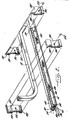
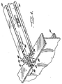
- the first and second clip members are then positioned on opposite sides of a floor beam 30 as shown in Figure 3 in which the seat tracks have been lifted from the floor beam for purposes of illustration.
- the elongate tongue 54 of the first clip member 50 is then inserted into the lengthwise extending channel 64 defined by the second clip member 58 . Once the elongate tongue has been fully inserted, the sills which extend outwardly from the beam attachment portions of the first and second clip members hook beneath the lower surface of the floor beam.
- the second clip member 58 preferably includes a tab 72 extending away from the beam attachment portion 60 in a direction opposite the elongate rails 62 . As shown in Figure 3, the tab defines a hole 74 therethrough.
- the elongate tongue 54 of the first clip member 50 of this embodiment also defines a hole 76 that is positioned such that the holes are aligned once the elongate tongue is slidably received within the lengthwise extending channel 64 of the second clip member.
- a fastener 78 can then be inserted through the aligned holes to securably interconnect the first and second clip members in a manner which securely mounts the clip 44 to the floor beam. See Figure 4B.
- the first and second clip members can be fastened by any number of fasteners, including threaded fasteners.
- a unique fastener is provided for interconnecting the first and second clip members in a manner which minimizes the part count and reduces the installation time and labor costs in comparison with conventional aircraft seat mounting systems.
- the fastener 78 includes a longitudinally extending shaft 80 and an annular ferrule 82 mounted upon a portion of the shaft.
- the shaft generally has a stepped diameter and, more particularly, includes first and second portions that are sized such that the first portion 84 is larger in lateral cross section than the second portion 86 .
- the shaft also includes a first ring 88 proximate the end of the first portion that is opposite the second portion and a second ring 90 proximate the end of the second portion that is opposite the first portion. Therefore, the first and second rings generally form the opposed ends of the shaft. As shown, the first ring is larger in lateral cross section than the first portion and the second ring is larger in lateral cross section than the second portion. However, the second ring is preferably smaller in lateral cross section than the first ring such that the second ring can be inserted through the holes defined by the first and second clip members. However, the first ring is sized to have a diameter larger than the diameter of the holes defined by the first and second clip members such that the first ring limits further advancement of the shaft through the holes.
- the annular ferrule 82 is advanced over the second ring 90 and is mounted upon the second portion 86 of the shaft.
- the annular ferrule defines a lengthwise extending channel extending between opposed first and second ends.
- the diameter of the lengthwise extending channel defined by the ferrule is slightly less than the diameter of the second ring of the shaft.
- the annular ferrule preferably defines a slit 83 which permits the ferrule to elastically deform as the ferrule is advanced over the second ring such that the ferrule can be mounted upon the second portion of the shaft.
- the ferrule preferably has relatively thin walls.
- the annular ferrule will preferably have a wall thickness of between about 0.010 inch and about 0.014 inch.
- the ferrule can be formed of other materials, however, in which case the wall thickness of the annular ferrule must be appropriately sized such that the ferrule can elastically deform as the ferrule is advanced over the second ring. Due to the elastic nature of the deformation, the ferrule is securely mounted upon the second portion of the shaft and cannot be removed from the shaft during normal operating conditions of the interlocking seat track assembly system.
- the channel defined by the ferrule is smaller in lateral cross section than both the first portion of the shaft and the second ring that abut the opposed ends of the ferrule.
- the first and second clip members are securely interconnected.
- the fastener 78 retains the first and second clip members upon the first portion 84 of the shaft between the first ring 88 and the annular ferrule. Accordingly, both the first ring and at least a portion of the annular ferrule are larger in lateral cross-section than the aligned holes.
- the ferrule preferably has a rounded outer surface, such as a semi-spherical outer surface, that has at least one portion that is larger in lateral cross section than both the first portion of the shaft and the aligned holes.
- an alternative embodiment of the clip illustrated in Figure 15 includes a pair of fasteners for joining the opposite ends of the clip.
- the clip of Figure 15 is shown to include a pair of snap-on fasteners 78 as described above, the clip could include other types of fasteners, such as threaded fasteners, without departing from the spirit and scope of the present invention.
- the seat tracks 14 are generally positioned upon the floor beams 30 such that the tabs 48 that extend into the inner channel 36 of the seat track 14 are aligned with the floor beams.
- the clip 44 is then slid over the tabs 48 that extend into the inner channel 36 of the seat track 14 such that the tabs 48 are positioned between the elongate rails 62 of the second clip member 58 and the floor beam 30 . See, for example, Figure 4 in which one seat track has been removed for purposes of illustration.
- the lower surface 70 of the second clip member spaces the elongate rails away from the floor beam by a separation distance that equals or is slightly larger than the thickness of the tabs that extend into the inner channel of the seat track such that the inwardly extending tabs of the seat track are securely engaged between the elongate rails of the second clip member and the floor beam.
- the floor beam 30 preferably defines a notch 96 in each opposed edge for engaging the beam attachment portion of the respective clip members.
- the interlocking seat track assembly system of the present invention prevents displacement along the lengthwise extending floor beam.
- Each notch preferably has a predetermined depth that is substantially equal to the predetermined thickness of the respective beam attachment portion such that the beam attachment portions do not protrude significantly beyond the outer edges of the floor beam.
- the clip 44 of the present invention requires very few components in order to securely mount a seat track 14 to an underlying floor beam 30 , thereby simplifying the installation procedure and reducing the time required to install the clip.
- the interlocking seat track assembly system of the present invention also permits the clips to be readily removed, if desired, in order to remove the seats 12 and/or floor panels 16 without damaging the clip, the seat track or the floor beam. Further, the interlocking seat track assembly system maintains the structural integrity of the seat tracks and the floor beams by mounting the seat tracks to the floor beams without requiring holes to be drilled or otherwise formed in the seat tracks or the floor beams.
- the interlocking assembly system of the present invention permits panels, such as floor panels 16 , to be installed in a simplified manner.
- floor panels can also be attached to the seat tracks in order to form the floor of an aircraft cabin 10 .
- the seat tracks include a plurality of lobes 38 that extend outwardly from at least one and, more commonly, both side portions 34 of the U-shaped body portion.
- the outer bulbous structure 42 defines a recessed portion 96 that serves to attach the floor panel to the seat track as described below.
- one advantageous embodiment of the present invention includes a panel assembly 98 including a panel 16 and a rail 102 mounted to an edge of the panel and generally extending circumferentially about the panel.
- the panel will be hereinafter described as a floor panel that is connected to a seat track 14
- the panel can include other types of panels, such as the panels which form partitions within an aircraft cabin that define a lavatory or the galley, for example.
- the panel assembly of these other embodiments of the present invention need not be attached to the seat track, but can be attached to other structures, if so desired.
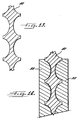
- the rail 102 generally has an upstanding wall portion 104 and a number of flanges which extend outwardly in both directions from the wall portion as shown in cross section in Figures 11A and 11B.
- at least one flange 106 preferably extends in a direction toward the interior of the panel 16 to facilitate mounting of the rail along the edge of the panel, such as by means of an adhesive and/or a variety of mechanical fasteners.
- the rail includes at least one flange 108 extending outwardly in a direction away from the panel and, more preferably, a pair of flanges extending outwardly in a spaced apart relationship in a direction away from the panel as shown in Figures 11A and 11B.
- the flange extending outwardly from the lower side of the panel can advantageously be formed of a number of different flange segments spaced apart along the length of the rail at the same spacing as the lobes 38 that extend outwardly from a side portion 34 of the seat track.
- the flange extending outwardly from the upper side of the panel can also be formed of a number of different flange segments spaced apart along the length of the rail at the same spacing as the lobes that extend outwardly from a side portion of the seat track and in alignment with the flange segments that extend outwardly from the lower side of the panel.
- the flanges which extend outwardly from the wall portion of the rail facilitate engagement of the rail and, in turn, the panel to the seat track 14 and, more particularly, to the lobes 38 which extend outwardly from a side portion 34 of the U-shaped body portion of the seat track.
- the panel assembly 98 also includes a number of cam lock assemblies 110 , typically formed of steel or titanium, which engage both the rail 102 and the seat track 14 , such as the lobes 38 which extend outwardly from a side portion 34 of the seat track.
- cam lock assemblies 110 typically formed of steel or titanium, which engage both the rail 102 and the seat track 14 , such as the lobes 38 which extend outwardly from a side portion 34 of the seat track.
- at least one of the flanges 108 that extends outwardly from the upper surface of the panel 16 includes a number of apertures for receiving respective ones of the cam lock assemblies. These apertures are spaced along the length of the flange at the same spacing as the lobes that extend outwardly from the side portion of the seat track.
- the cam lock assembly 110 includes a head portion 112 , a shaft portion 114 extending outwardly from the head portion, and a semi-circular cam 116 mounted upon the shaft.
- the shaft portion is positioned to extend through a respective aperture defined by the flange 108 of the rail 102 .
- the flange of the rail also defines a recessed portion for receiving the head portion of the cam lock assembly such that the head portion is relatively flush with the exterior of the flange.
- the semi-circular cam 116 is mounted upon the shaft portion such that the cam rotates with the shaft portion.
- the shaft portion can include a medial portion 120 having a generally rectangularly shaped lateral cross sectional shape.
- the cam also therefore defines a generally rectangularly shaped aperture 122 that is sized and shaped to match the rectangularly shaped medial portion of the shaft portion.
- the cam can be mounted upon the medial portion of the shaft portion so as to rotate therewith.
- the cam lock assembly 110 can also include a base 124 for mounting upon the end 115 of the shaft portion 114 opposite the head portion 112 to thereby secure the cam 116 upon the shaft.
- the end of the shaft portion opposite the head portion generally has a circular lateral cross-sectional shape.
- the base generally includes a tubular portion 126 for receiving the end of the shaft portion opposite the head portion.
- the tubular portion is typically open at one end and defines an internal shape, i.e., circular, that matches the shape of the end of the shaft portion opposite the head portion.
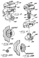
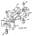
- the end 115 of the shaft portion 114 opposite the head portion 112 preferably defines a reduced diameter portion 117 and at least one and, more preferably, a pair of orthogonal slits 119 extending longitudinally from the end of the shaft portion opposite the head portion through at least the reduced diameter portion. See Figure 10C.
- the slits defined by the end of the shaft portion opposite the head portion preferably extend laterally completely across the end of the shaft portion opposite the head portion to thereby permit the end of the shaft portion opposite the head portion to flex or compress somewhat as the base 124 is mounted thereto.
- the interior opening defined by the tubular portion 126 of the base preferably defines an inwardly extending rib 127 for engaging the reduced diameter portion of the end or the shaft portion opposite the head portion as shown in Figures 11A and 11B.
- the base can be securely mounted upon the end of the shaft portion opposite the head portion.
- the base 124 also preferably includes an enlarged end portion 128 mounted to the end of the tubular portion 126 opposite the open end.
- the rail 102 preferably defines a recess for receiving the enlarged end portion of the base such that the enlarged end portion of the base is either recessed or flush mounted relative to the exterior of the rail.
- the shaft portion 114 of the cam lock assembly 110 is extended through the aperture 112 defined by the flange 108 of the rail 102 and the cam 116 and the base 124 are mounted upon the shaft portion.
- the cam is disposed between the flanges.
- the cam lock assembly is also initially positioned such that the semi-circular cam is directed toward the panel as shown in the unlocked position of Figures 10B and 11B.
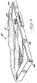
- the panel assembly 98 is then placed adjacent the other structure to which it is to be interconnected, such as a seat track 14 as shown in Figures 5 and 7.
- the flanges 108 which extend outwardly from the rail 102 are generally positioned on the opposite sides of the lobes 38 , i.e., above and below the lobes, which extend outwardly from the side portion 34 of the U-shaped body portion of the seat track.
- the panel assembly is positioned such that the cam lock assemblies 110 are positioned immediately adjacent respective lobes of the seat track.
- each cam lock assembly 110 is rotated such that the semi-circular cam 116 also rotates into the locked position so as to extend outwardly from the panel assembly 98 and into engagement with the recessed portion 96 defined by the respective lobe 38 of the seat track 14 as shown in Figures 10A and 11A.
- the panel assembly engages the seat track so as to effectively limit undesirable movement the panel 16 relative to the seat track.
- the head portion 112 preferably includes at least one slot 130 for engagement by an appropriate tool, such as a screwdriver.
- the head portion can include indicia 132 , such as another slot, indicative of the direction of the semi-circular cam 116 such that an installer can quickly determine by visual inspection whether the semi-circular cam is positioned so as to engage the respective lobe 38 of the seat track 14 .
- the panel assembly 98 of the present invention can be utilized to attach a variety of panels to a variety of other structures, in addition to the seat track 14 of the present invention.
- the panel assembly can be utilized to form partitions which define, for example, lavatories or galleys within an aircraft cabin 10 .
- the interlocking assembly system of the present invention also permits panels 16 , such as floor panels, to be securely connected to adjacent structures, such as the seat track 14 of the present invention with very few components, thereby simplifying the installation procedure and reducing the time required to mount the panels.
- the interlocking assembly system of the present invention also permits the cam lock assemblies 110 to be readily removed, if desired, in order to remove the panels in an efficient manner without damaging the cam lock assembly, the panel or the seat track.
Landscapes
- Engineering & Computer Science (AREA)
- Mechanical Engineering (AREA)
- General Engineering & Computer Science (AREA)
- Aviation & Aerospace Engineering (AREA)
- Transportation (AREA)
- Seats For Vehicles (AREA)
- Insertion Pins And Rivets (AREA)
Priority Applications (1)
| Application Number | Priority Date | Filing Date | Title |
|---|---|---|---|
| EP03078247A EP1405786A3 (fr) | 1997-12-09 | 1998-12-08 | Organe d'ancrage de siège pour aéronef |
Applications Claiming Priority (2)
| Application Number | Priority Date | Filing Date | Title |
|---|---|---|---|
| US08/987,659 US6086018A (en) | 1997-12-09 | 1997-12-09 | Interlocking assembly system for an aircraft cabin |
| US987659 | 1997-12-09 |
Related Child Applications (1)
| Application Number | Title | Priority Date | Filing Date |
|---|---|---|---|
| EP03078247A Division EP1405786A3 (fr) | 1997-12-09 | 1998-12-08 | Organe d'ancrage de siège pour aéronef |
Publications (3)
| Publication Number | Publication Date |
|---|---|
| EP0922632A2 true EP0922632A2 (fr) | 1999-06-16 |
| EP0922632A3 EP0922632A3 (fr) | 2000-08-30 |
| EP0922632B1 EP0922632B1 (fr) | 2006-06-07 |
Family
ID=25533450
Family Applications (2)
| Application Number | Title | Priority Date | Filing Date |
|---|---|---|---|
| EP03078247A Withdrawn EP1405786A3 (fr) | 1997-12-09 | 1998-12-08 | Organe d'ancrage de siège pour aéronef |
| EP98204156A Expired - Lifetime EP0922632B1 (fr) | 1997-12-09 | 1998-12-08 | Organe d'ancrage de siège pour aéronef |
Family Applications Before (1)
| Application Number | Title | Priority Date | Filing Date |
|---|---|---|---|
| EP03078247A Withdrawn EP1405786A3 (fr) | 1997-12-09 | 1998-12-08 | Organe d'ancrage de siège pour aéronef |
Country Status (3)
| Country | Link |
|---|---|
| US (1) | US6086018A (fr) |
| EP (2) | EP1405786A3 (fr) |
| DE (1) | DE69834797T2 (fr) |
Cited By (18)
| Publication number | Priority date | Publication date | Assignee | Title |
|---|---|---|---|---|
| EP1544105A1 (fr) * | 2003-12-19 | 2005-06-22 | Airbus Deutschland GmbH | Rail de fixation pour siège |
| DE10360807A1 (de) * | 2003-12-19 | 2005-09-08 | Airbus Deutschland Gmbh | Sitzschiene |
| US7281685B2 (en) | 2004-08-20 | 2007-10-16 | Airbus Deutschland Gmbh | Flush-top seat mounting rail for passenger aircraft |
| DE102006043020A1 (de) * | 2006-09-13 | 2008-03-27 | Airbus Deutschland Gmbh | Trägerelement und Befestigungssystem für Fahrzeugteile eines Fahrzeugs, insbesondere eines Luft- und/oder Raumfahrzeugs |
| WO2008036042A1 (fr) * | 2006-09-21 | 2008-03-27 | Patent Linx Ab | Système de construction et procédé de fixation d'équipement dans un véhicule |
| WO2009031987A1 (fr) * | 2007-09-04 | 2009-03-12 | Temsa Sanayi Ve Ticaret A.S. | Glissière pour sièges de passagers d'autobus et installation de cette dernière |
| DE102009028534A1 (de) * | 2009-08-14 | 2011-02-17 | Airbus Operations Gmbh | Befestigungssystem in einem Luft- und Raumfahrzeug |
| DE102009028903A1 (de) * | 2009-08-26 | 2011-03-10 | Airbus Operations Gmbh | Befestigungssystem in einem Luft- und Raumfahrzeug |
| EP2295318A1 (fr) * | 2009-09-11 | 2011-03-16 | AMI Industries, Inc. | Support d'équipement d'aéronef |
| DE202012102995U1 (de) * | 2012-08-09 | 2013-11-13 | Rehau Ag + Co | Vorrichtung zur Fixierung von Schienen |
| DE102009028533B4 (de) * | 2009-08-14 | 2014-06-18 | Airbus Operations Gmbh | Befestigungssystem in einem Luft- und Raumfahrzeug |
| DE102007004554B4 (de) * | 2007-01-30 | 2015-08-27 | Airbus Operations Gmbh | Schiene zur Positionierung und Arretierung von Bauteilen und eines dazugehörigen Fittings |
| EP3486161A3 (fr) * | 2017-11-15 | 2019-08-21 | Airbus Operations GmbH | Module de plancher pourvu d'élément de plancher monolithique ainsi que zone d'aéronef et aéronef doté d'un module de plancher |
| DE102018103514A1 (de) * | 2018-02-16 | 2019-08-22 | Airbus Operations Gmbh | Befestigungssystem zum Befestigen von Einbauten an einer Schiene in einem Fahrzeug |
| FR3089949A1 (fr) | 2018-12-18 | 2020-06-19 | Figeac Aero | Rail de siège et procédé de fabrication |
| CN113636084A (zh) * | 2020-05-10 | 2021-11-12 | 波音公司 | 滑动接头、机身结构组件及其相关方法 |
| US11413987B2 (en) | 2019-09-03 | 2022-08-16 | The Boeing Company | Electromagnetic seat attachment and seat power |
| US11584259B2 (en) | 2020-01-17 | 2023-02-21 | The Boeing Company | Seat fittings for attaching seats to seat tracks in a vehicle and related systems and methods |
Families Citing this family (27)
| Publication number | Priority date | Publication date | Assignee | Title |
|---|---|---|---|---|
| JP3919063B2 (ja) * | 2000-10-31 | 2007-05-23 | スズキ株式会社 | シートのスライド構造 |
| US6712316B2 (en) * | 2002-08-01 | 2004-03-30 | The Boeing Company | Snap-on sidewall assembly |
| US7168674B2 (en) * | 2004-12-14 | 2007-01-30 | Mcfarlane Daniel S | Aircraft seat track repair device |
| WO2006089191A1 (fr) * | 2005-02-18 | 2006-08-24 | Johnson Controls Technology Company | Siege de vehicule |
| ES2272153B1 (es) * | 2005-03-17 | 2008-01-01 | Figueras International Seating, S.A. | Instalacion movil de filas de butacas. |
| FR2891239B1 (fr) * | 2005-09-28 | 2009-04-17 | Airbus France Sas | Panneau de plancher et installation pour la fixation d'elements d'amenagement comportant de tels panneaux |
| US20070295866A1 (en) * | 2006-06-26 | 2007-12-27 | Yang Chih-Hong | Wall mounting bracket with a slide rail assembly |
| US7628370B2 (en) * | 2006-07-03 | 2009-12-08 | Weber Aircraft Llc | Mounting interface systems and methods for purposes of testing seat tracks |
| US7775478B2 (en) * | 2006-09-29 | 2010-08-17 | The Boeing Company | Floor beam assembly, system, and associated method |
| DE102007032235B4 (de) * | 2007-07-11 | 2015-05-07 | Airbus Operations Gmbh | Leichtes Schienensystem zur Krafteinleitung großer Lasten in eine Struktur |
| DE102008020789A1 (de) * | 2008-04-25 | 2009-11-05 | Airbus Deutschland Gmbh | Befestigungssystem sowie Verfahren zum Befestigen eines Elementes einer Flugzeuginnenausstattung |
| ES2622877T3 (es) | 2009-01-22 | 2017-07-07 | Keybioscience Ag | Tratamiento para la obesidad |
| DE102010018272A1 (de) * | 2010-04-26 | 2011-10-27 | Airbus Operations Gmbh | Schienensystem und Verfahren zur Montage einer Komponente in einem Flugzeug |
| US9102753B2 (en) | 2011-06-15 | 2015-08-11 | Ugp Therapeutics, Inc. | Anti-inflammatory pharmaceutical products |
| FR2988687B1 (fr) * | 2012-03-30 | 2014-09-05 | Sogeclair | Panneau monobloc de plancher pour vehicule de transport, plancher et vehicule de transport comprenant un tel panneau monobloc |
| EP2697117B1 (fr) * | 2012-07-06 | 2019-08-28 | Zodiac Seats France | Ensemble châssis de base de sièges de passager |
| DE102012021548A1 (de) * | 2012-11-02 | 2014-05-08 | Klaus ACKERMANN | Fahrzeuginnenraum |
| DE102013103662A1 (de) * | 2013-04-11 | 2014-10-16 | Airbus Operations Gmbh | Haltevorrichtung für Passagiersitze und Passagiersitzsystem mit flexibler Sitzanordnung für Passagiertransportmittel |
| US9109353B1 (en) * | 2013-08-13 | 2015-08-18 | The Boeing Company | Mounting assembly and method for connecting sidewall panels to a support structure |
| US9545990B2 (en) * | 2014-11-20 | 2017-01-17 | The Boeing Company | Floor panel retention system |
| EP3484767B1 (fr) * | 2016-07-18 | 2020-09-02 | Safran Seats USA LLC | Collier de serrage de bâti de siège |
| US10836463B2 (en) * | 2017-07-06 | 2020-11-17 | The Boeing Company | Aircraft floor panel floating connection system |
| DE102018108304B4 (de) * | 2018-04-09 | 2026-02-05 | Airbus Operations Gmbh | Schienensystem sowie Passagiersitzsystem für eine Kabine eines Fahrzeugs und Fahrzeug mit einer Kabine |
| US11975839B2 (en) * | 2018-06-13 | 2024-05-07 | Safran Seats Usa Llc | Lightweight passenger privacy screen |
| CN113272225B (zh) * | 2018-10-31 | 2024-03-01 | 赛峰座椅美国有限责任公司 | 弯曲管座椅结构 |
| US11912415B2 (en) | 2021-01-29 | 2024-02-27 | Textron Innovations Inc. | Rotatable insert for aircraft seat base |
| EP4378821A1 (fr) * | 2022-11-30 | 2024-06-05 | Airbus Operations GmbH | Système de plancher pour une cabine de véhicule avec liaison de panneau de plancher par complémentarité de forme |
Citations (2)
| Publication number | Priority date | Publication date | Assignee | Title |
|---|---|---|---|---|
| US4185799A (en) | 1978-03-14 | 1980-01-29 | Boeing Commercial Airplane Company | Aircraft partition mounting assembly |
| US4936527A (en) | 1985-09-12 | 1990-06-26 | The Boeing Company | Movable seating system for aircraft |
Family Cites Families (33)
| Publication number | Priority date | Publication date | Assignee | Title |
|---|---|---|---|---|
| US855048A (en) * | 1906-09-26 | 1907-05-28 | William Curlett | Building-wall. |
| US1343234A (en) * | 1917-03-17 | 1920-06-15 | Stevens Partition And Floor De | Floor construction |
| US2676679A (en) * | 1948-06-26 | 1954-04-27 | Manley R Price | Joint construction |
| US3266209A (en) * | 1960-12-27 | 1966-08-16 | Georgia Marble Co | Anchoring system for the installation of slabs on vertical and overhead surfaces |
| GB1014489A (en) * | 1962-09-04 | 1965-12-22 | Ft Products Ltd | Improvements in and relating to fasteners |
| US3547472A (en) * | 1968-06-07 | 1970-12-15 | Ernest W Ehrman | Connector means and like elements for juncture purposes |
| US4367970A (en) * | 1979-10-05 | 1983-01-11 | Franz Louis J | Die insert lock screws |
| FR2480212A1 (fr) * | 1980-04-15 | 1981-10-16 | Linderoth Hans | Dispositif de securite pour le transport dans un vehicule d'une personne circulant en fauteuil roulant |
| AU6116380A (en) * | 1980-08-07 | 1982-02-11 | Comet Transport Equipment Ltd. | Spigot and socket locking arrangement |
| DE3209284A1 (de) * | 1982-03-13 | 1983-09-15 | Karl 6969 Hardheim Hock | Vorrichtung zur loesbaren verbindung zweier zusammengesteckter bauteile |
| US4509888A (en) * | 1982-08-04 | 1985-04-09 | Fairchild Industries, Inc. | Track fastener |
| US4703603A (en) * | 1985-06-17 | 1987-11-03 | Altech Industries, Inc. | Plywood sheeting spacer clip |
| DE3603707A1 (de) * | 1986-02-06 | 1987-08-13 | Iveco Magirus | Wagenkastengerippe |
| US4956956A (en) * | 1987-04-22 | 1990-09-18 | Julius Blum Gesellschaft M.B.H. | Connector for connecting two elements |
| US4796837A (en) * | 1987-07-27 | 1989-01-10 | Dowd Eugene G | Leg seat track fitting with improved bearing member |
| US4911381A (en) * | 1987-12-28 | 1990-03-27 | Simula, Inc. | Energy-absorbing leg assembly for aircraft passenger seats |
| CA1304907C (fr) * | 1988-03-29 | 1992-07-14 | Gad Shaanan | Dispositif a came servant a assembler des panneaux d'elements de mobilier |
| US4843792A (en) * | 1988-06-27 | 1989-07-04 | Stageright Corporation | Socket support and interlock for staging panels |
| US5088841A (en) * | 1988-11-30 | 1992-02-18 | Fuji Kiko Company, Limited | Seat arrangement for automotive vehicle with seat position adjusting system |
| US5083727A (en) * | 1990-01-02 | 1992-01-28 | The Boeing Company | Aircraft cabin system for selectivley locating interior units |
| US4962914A (en) * | 1990-02-26 | 1990-10-16 | Taylor Alva R | Fence |
| GB2246826B (en) * | 1990-08-07 | 1993-08-04 | Titus Int Ltd | Fastening devices |
| US5058347A (en) * | 1990-09-18 | 1991-10-22 | Herman Miller, Inc. | Panel connector system |
| US5078530A (en) * | 1991-04-26 | 1992-01-07 | Permanent Solution Industries, Inc. | Plastic coupling device for connecting two building elements |
| US5178346A (en) * | 1991-07-12 | 1993-01-12 | Burns Aerospace Corporation | Track fastener apparatus and assembly |
| US5265828A (en) * | 1991-11-08 | 1993-11-30 | Bennington Thomas E | Child safety seat adaptable to aircraft seat attach points |
| US5400554A (en) * | 1994-01-14 | 1995-03-28 | Lo; Chin-Fa | Elevated floor board |
| US5537795A (en) * | 1994-01-24 | 1996-07-23 | California Prison Industry Authority | Hinge and rail connection system |
| US5383630A (en) * | 1994-03-17 | 1995-01-24 | Teleflex Incorporated | Main deck quick change cargo system |
| US5529378A (en) * | 1994-10-17 | 1996-06-25 | Hoover Universal, Inc. | Movable vehicle seat assembly with improved latch |
| US5580204A (en) * | 1995-03-07 | 1996-12-03 | Textron Inc. | Panel attachment system |
| US5558369A (en) * | 1995-06-20 | 1996-09-24 | Chrysler Corporation | Tapping plate and retention bracket assembly |
| US5871318A (en) * | 1997-11-12 | 1999-02-16 | Be Aerospace, Inc. | Quick-release track fastener |
-
1997
- 1997-12-09 US US08/987,659 patent/US6086018A/en not_active Expired - Fee Related
-
1998
- 1998-12-08 DE DE69834797T patent/DE69834797T2/de not_active Expired - Lifetime
- 1998-12-08 EP EP03078247A patent/EP1405786A3/fr not_active Withdrawn
- 1998-12-08 EP EP98204156A patent/EP0922632B1/fr not_active Expired - Lifetime
Patent Citations (2)
| Publication number | Priority date | Publication date | Assignee | Title |
|---|---|---|---|---|
| US4185799A (en) | 1978-03-14 | 1980-01-29 | Boeing Commercial Airplane Company | Aircraft partition mounting assembly |
| US4936527A (en) | 1985-09-12 | 1990-06-26 | The Boeing Company | Movable seating system for aircraft |
Cited By (31)
| Publication number | Priority date | Publication date | Assignee | Title |
|---|---|---|---|---|
| DE10360809A1 (de) * | 2003-12-19 | 2005-07-28 | Airbus Deutschland Gmbh | Sitzschiene |
| DE10360807A1 (de) * | 2003-12-19 | 2005-09-08 | Airbus Deutschland Gmbh | Sitzschiene |
| US7100885B2 (en) | 2003-12-19 | 2006-09-05 | Airbus Deutschland Gmbh | Seat mounting rail, particularly for a commercial aircraft |
| US7207756B2 (en) | 2003-12-19 | 2007-04-24 | Airbus Deutschland Gmbh | Seat mounting rail, particularly for a commercial aircraft |
| DE10360807B4 (de) * | 2003-12-19 | 2007-09-06 | Airbus Deutschland Gmbh | Sitzschiene |
| EP1544105A1 (fr) * | 2003-12-19 | 2005-06-22 | Airbus Deutschland GmbH | Rail de fixation pour siège |
| US7281685B2 (en) | 2004-08-20 | 2007-10-16 | Airbus Deutschland Gmbh | Flush-top seat mounting rail for passenger aircraft |
| DE102006043020B4 (de) * | 2006-09-13 | 2009-09-24 | Airbus Deutschland Gmbh | Trägerelement und Befestigungssystem für Fahrzeugteile eines Fahrzeugs, insbesondere eines Luft- und/oder Raumfahrzeugs |
| DE102006043020A1 (de) * | 2006-09-13 | 2008-03-27 | Airbus Deutschland Gmbh | Trägerelement und Befestigungssystem für Fahrzeugteile eines Fahrzeugs, insbesondere eines Luft- und/oder Raumfahrzeugs |
| WO2008036042A1 (fr) * | 2006-09-21 | 2008-03-27 | Patent Linx Ab | Système de construction et procédé de fixation d'équipement dans un véhicule |
| DE102007004554B4 (de) * | 2007-01-30 | 2015-08-27 | Airbus Operations Gmbh | Schiene zur Positionierung und Arretierung von Bauteilen und eines dazugehörigen Fittings |
| WO2009031987A1 (fr) * | 2007-09-04 | 2009-03-12 | Temsa Sanayi Ve Ticaret A.S. | Glissière pour sièges de passagers d'autobus et installation de cette dernière |
| DE102009028534A1 (de) * | 2009-08-14 | 2011-02-17 | Airbus Operations Gmbh | Befestigungssystem in einem Luft- und Raumfahrzeug |
| DE102009028534B4 (de) * | 2009-08-14 | 2017-01-05 | Airbus Operations Gmbh | Befestigungssystem in einem Luft- und Raumfahrzeug |
| DE102009028533B4 (de) * | 2009-08-14 | 2014-06-18 | Airbus Operations Gmbh | Befestigungssystem in einem Luft- und Raumfahrzeug |
| DE102009028903A1 (de) * | 2009-08-26 | 2011-03-10 | Airbus Operations Gmbh | Befestigungssystem in einem Luft- und Raumfahrzeug |
| DE102009028903B4 (de) * | 2009-08-26 | 2016-12-29 | Airbus Operations Gmbh | Befestigungssystem in einem Luft- und Raumfahrzeug |
| US8231097B2 (en) | 2009-09-11 | 2012-07-31 | Ami Industries, Inc. | Aircraft equipment support |
| EP2295318A1 (fr) * | 2009-09-11 | 2011-03-16 | AMI Industries, Inc. | Support d'équipement d'aéronef |
| DE202012102995U1 (de) * | 2012-08-09 | 2013-11-13 | Rehau Ag + Co | Vorrichtung zur Fixierung von Schienen |
| EP3486161A3 (fr) * | 2017-11-15 | 2019-08-21 | Airbus Operations GmbH | Module de plancher pourvu d'élément de plancher monolithique ainsi que zone d'aéronef et aéronef doté d'un module de plancher |
| US11161587B2 (en) | 2017-11-15 | 2021-11-02 | Airbus Operations Gmbh | Floor assembly comprising a monolithic floor element, and aircraft region and aircraft comprising a floor assembly |
| US11187256B2 (en) | 2018-02-16 | 2021-11-30 | Airbus Operations Gmbh | Fastening system for fastening fittings to a rail in a vehicle |
| DE102018103514A1 (de) * | 2018-02-16 | 2019-08-22 | Airbus Operations Gmbh | Befestigungssystem zum Befestigen von Einbauten an einer Schiene in einem Fahrzeug |
| FR3089949A1 (fr) | 2018-12-18 | 2020-06-19 | Figeac Aero | Rail de siège et procédé de fabrication |
| US11413987B2 (en) | 2019-09-03 | 2022-08-16 | The Boeing Company | Electromagnetic seat attachment and seat power |
| US11584259B2 (en) | 2020-01-17 | 2023-02-21 | The Boeing Company | Seat fittings for attaching seats to seat tracks in a vehicle and related systems and methods |
| US12403795B2 (en) | 2020-01-17 | 2025-09-02 | The Boeing Company | Seat fittings for attaching seats to seat tracks in a vehicle and related systems and methods |
| EP3909845A1 (fr) * | 2020-05-10 | 2021-11-17 | The Boeing Company | Joint coulissant pour l'allègement de la charge |
| CN113636084A (zh) * | 2020-05-10 | 2021-11-12 | 波音公司 | 滑动接头、机身结构组件及其相关方法 |
| US11511863B2 (en) | 2020-05-10 | 2022-11-29 | The Boeing Company | Sliding joint for load alleviation |
Also Published As
| Publication number | Publication date |
|---|---|
| EP0922632A3 (fr) | 2000-08-30 |
| EP1405786A3 (fr) | 2004-08-25 |
| EP0922632B1 (fr) | 2006-06-07 |
| US6086018A (en) | 2000-07-11 |
| DE69834797D1 (de) | 2006-07-20 |
| DE69834797T2 (de) | 2007-06-14 |
| EP1405786A2 (fr) | 2004-04-07 |
Similar Documents
| Publication | Publication Date | Title |
|---|---|---|
| US6086018A (en) | Interlocking assembly system for an aircraft cabin | |
| CA2185778C (fr) | Fixation a pression pour panneaux montes en affleurement | |
| US7120971B2 (en) | Low insertion effort u-base retainer | |
| US7114221B2 (en) | Two-piece interior trim retainer | |
| EP0892892B1 (fr) | Fixation de serrage montee par encliquettement en aveugle | |
| US6042296A (en) | Snap-in fastener for panels | |
| EP1087150A2 (fr) | Ecrou à emboítement | |
| US7272873B2 (en) | Sill plate retainer | |
| US7017788B2 (en) | Adapter bracket for securing a support foot of a article carrier support rail to an outer surface of a vehicle having a roof channel | |
| US20020007537A1 (en) | Resilient clip fastener | |
| US20200086966A1 (en) | Aircraft flooring systems and related methods | |
| EP0917920A3 (fr) | Système et procédé de rivetage | |
| EP1117564B1 (fr) | Garniture de plafond modulaire comportant une lampe s'alignant automatiquement | |
| US20150175388A1 (en) | System and Method For Assembling An Elevator Cab | |
| US8745951B2 (en) | Interlocking flange and fastening system and method for securing together two panels | |
| EP3696428B1 (fr) | Attache de fixation comportant des pattes d'épaule stabilisatrices | |
| US5209620A (en) | Fastener with differentially inclined axes | |
| US20230399106A1 (en) | Seat assembly | |
| EP4071056B1 (fr) | Bande de protection | |
| EP0401151A2 (fr) | Assemblage pour boîtiers | |
| EP1484513A1 (fr) | Element de fixation élastique avec dispositif anti-rotation | |
| CN113200138A (zh) | 一种将面板连接至支撑构件的组件 | |
| US20260012126A1 (en) | Snap-in bracket for installation of solar modules on tracker | |
| US20060059784A1 (en) | Door module positioning system | |
| GB2090366A (en) | Joining structural elements |
Legal Events
| Date | Code | Title | Description |
|---|---|---|---|
| PUAI | Public reference made under article 153(3) epc to a published international application that has entered the european phase |
Free format text: ORIGINAL CODE: 0009012 |
|
| AK | Designated contracting states |
Kind code of ref document: A2 Designated state(s): DE FR GB |
|
| AX | Request for extension of the european patent |
Free format text: AL;LT;LV;MK;RO;SI |
|
| RIC1 | Information provided on ipc code assigned before grant |
Free format text: 7B 64C 1/20 A, 7B 64D 11/06 B, 7B 64C 1/18 B, 7B 60N 2/015 B |
|
| PUAL | Search report despatched |
Free format text: ORIGINAL CODE: 0009013 |
|
| AK | Designated contracting states |
Kind code of ref document: A3 Designated state(s): AT BE CH CY DE DK ES FI FR GB GR IE IT LI LU MC NL PT SE |
|
| AX | Request for extension of the european patent |
Free format text: AL;LT;LV;MK;RO;SI |
|
| 17P | Request for examination filed |
Effective date: 20010205 |
|
| AKX | Designation fees paid |
Free format text: DE FR GB |
|
| RIC1 | Information provided on ipc code assigned before grant |
Free format text: 7B 64C 1/18 A, 7B 60N 2/015 B |
|
| 17Q | First examination report despatched |
Effective date: 20030225 |
|
| GRAP | Despatch of communication of intention to grant a patent |
Free format text: ORIGINAL CODE: EPIDOSNIGR1 |
|
| GRAS | Grant fee paid |
Free format text: ORIGINAL CODE: EPIDOSNIGR3 |
|
| GRAA | (expected) grant |
Free format text: ORIGINAL CODE: 0009210 |
|
| AK | Designated contracting states |
Kind code of ref document: B1 Designated state(s): DE FR GB |
|
| REG | Reference to a national code |
Ref country code: GB Ref legal event code: FG4D |
|
| REF | Corresponds to: |
Ref document number: 69834797 Country of ref document: DE Date of ref document: 20060720 Kind code of ref document: P |
|
| ET | Fr: translation filed | ||
| PLBE | No opposition filed within time limit |
Free format text: ORIGINAL CODE: 0009261 |
|
| STAA | Information on the status of an ep patent application or granted ep patent |
Free format text: STATUS: NO OPPOSITION FILED WITHIN TIME LIMIT |
|
| 26N | No opposition filed |
Effective date: 20070308 |
|
| REG | Reference to a national code |
Ref country code: FR Ref legal event code: PLFP Year of fee payment: 18 |
|
| REG | Reference to a national code |
Ref country code: FR Ref legal event code: PLFP Year of fee payment: 19 |
|
| PGFP | Annual fee paid to national office [announced via postgrant information from national office to epo] |
Ref country code: GB Payment date: 20161228 Year of fee payment: 19 |
|
| PGFP | Annual fee paid to national office [announced via postgrant information from national office to epo] |
Ref country code: FR Payment date: 20161227 Year of fee payment: 19 |
|
| PGFP | Annual fee paid to national office [announced via postgrant information from national office to epo] |
Ref country code: DE Payment date: 20161229 Year of fee payment: 19 |
|
| REG | Reference to a national code |
Ref country code: DE Ref legal event code: R119 Ref document number: 69834797 Country of ref document: DE |
|
| GBPC | Gb: european patent ceased through non-payment of renewal fee |
Effective date: 20171208 |
|
| REG | Reference to a national code |
Ref country code: FR Ref legal event code: ST Effective date: 20180831 |
|
| PG25 | Lapsed in a contracting state [announced via postgrant information from national office to epo] |
Ref country code: DE Free format text: LAPSE BECAUSE OF NON-PAYMENT OF DUE FEES Effective date: 20180703 Ref country code: FR Free format text: LAPSE BECAUSE OF NON-PAYMENT OF DUE FEES Effective date: 20180102 |
|
| PG25 | Lapsed in a contracting state [announced via postgrant information from national office to epo] |
Ref country code: GB Free format text: LAPSE BECAUSE OF NON-PAYMENT OF DUE FEES Effective date: 20171208 |