EP0924096A1 - Procédé de marquage utilisant des rayons actiniques et produit moulé marqué par ce procédé - Google Patents
Procédé de marquage utilisant des rayons actiniques et produit moulé marqué par ce procédé Download PDFInfo
- Publication number
- EP0924096A1 EP0924096A1 EP98310164A EP98310164A EP0924096A1 EP 0924096 A1 EP0924096 A1 EP 0924096A1 EP 98310164 A EP98310164 A EP 98310164A EP 98310164 A EP98310164 A EP 98310164A EP 0924096 A1 EP0924096 A1 EP 0924096A1
- Authority
- EP
- European Patent Office
- Prior art keywords
- paint
- molding
- film
- mark
- energy ray
- Prior art date
- Legal status (The legal status is an assumption and is not a legal conclusion. Google has not performed a legal analysis and makes no representation as to the accuracy of the status listed.)
- Granted
Links
Images



Classifications
-
- B—PERFORMING OPERATIONS; TRANSPORTING
- B41—PRINTING; LINING MACHINES; TYPEWRITERS; STAMPS
- B41M—PRINTING, DUPLICATING, MARKING, OR COPYING PROCESSES; COLOUR PRINTING
- B41M5/00—Duplicating or marking methods; Sheet materials for use therein
- B41M5/26—Thermography ; Marking by high energetic means, e.g. laser otherwise than by burning, and characterised by the material used
- B41M5/382—Contact thermal transfer or sublimation processes
- B41M5/38207—Contact thermal transfer or sublimation processes characterised by aspects not provided for in groups B41M5/385 - B41M5/395
-
- B—PERFORMING OPERATIONS; TRANSPORTING
- B41—PRINTING; LINING MACHINES; TYPEWRITERS; STAMPS
- B41M—PRINTING, DUPLICATING, MARKING, OR COPYING PROCESSES; COLOUR PRINTING
- B41M5/00—Duplicating or marking methods; Sheet materials for use therein
- B41M5/26—Thermography ; Marking by high energetic means, e.g. laser otherwise than by burning, and characterised by the material used
- B41M5/267—Marking of plastic artifacts, e.g. with laser
-
- Y—GENERAL TAGGING OF NEW TECHNOLOGICAL DEVELOPMENTS; GENERAL TAGGING OF CROSS-SECTIONAL TECHNOLOGIES SPANNING OVER SEVERAL SECTIONS OF THE IPC; TECHNICAL SUBJECTS COVERED BY FORMER USPC CROSS-REFERENCE ART COLLECTIONS [XRACs] AND DIGESTS
- Y10—TECHNICAL SUBJECTS COVERED BY FORMER USPC
- Y10T—TECHNICAL SUBJECTS COVERED BY FORMER US CLASSIFICATION
- Y10T428/00—Stock material or miscellaneous articles
- Y10T428/24—Structurally defined web or sheet [e.g., overall dimension, etc.]
- Y10T428/24802—Discontinuous or differential coating, impregnation or bond [e.g., artwork, printing, retouched photograph, etc.]
-
- Y—GENERAL TAGGING OF NEW TECHNOLOGICAL DEVELOPMENTS; GENERAL TAGGING OF CROSS-SECTIONAL TECHNOLOGIES SPANNING OVER SEVERAL SECTIONS OF THE IPC; TECHNICAL SUBJECTS COVERED BY FORMER USPC CROSS-REFERENCE ART COLLECTIONS [XRACs] AND DIGESTS
- Y10—TECHNICAL SUBJECTS COVERED BY FORMER USPC
- Y10T—TECHNICAL SUBJECTS COVERED BY FORMER US CLASSIFICATION
- Y10T428/00—Stock material or miscellaneous articles
- Y10T428/24—Structurally defined web or sheet [e.g., overall dimension, etc.]
- Y10T428/24802—Discontinuous or differential coating, impregnation or bond [e.g., artwork, printing, retouched photograph, etc.]
- Y10T428/24835—Discontinuous or differential coating, impregnation or bond [e.g., artwork, printing, retouched photograph, etc.] including developable image or soluble portion in coating or impregnation [e.g., safety paper, etc.]
Definitions
- the present invention relates to a marking method of displaying characters and patterns on moldings by laser beam, electron beam, heat ray or other energy ray, and to marked moldings
- a plurality of coat films are formed on the surface of a resin molding by applying paints of different colors preliminarily, and only the surface layer or a plurality of coat films are removed partly by emitting laser beam, so that a desired is left over.
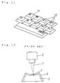
- Fig. 12 is a front view for explaining a method of discoloring the filler in the resin molding
- Fig. 13 is an essential sectional front view for explaining a method of removing the coat film of the paint on the resin molding.
- the surface layer containing a paint powder 4 which is discolored by the action of laser beam is formed on the surface of a resin molding 3.
- a laser beam 1 controlled by a deflection device 2 is emitted to the surface layer, and the portion exposed to the laser beam is changed in color, and a mark 5 is formed.
- the mark 5 is formed on the surface layer of the resin molding 3.
- Fig. 13 three color paints are applied sequentially on the surface of a resin molding 6, and three layers of coat films 7, 8, 9 are formed.
- a laser beam 1 controlled by a deflection device 2 is controlled in reflection according to the emitting position corresponding to a desired character or pattern, and is also controlled in the amount of energy, and is emitted to the surface coat film 7 side of the resin molding 6.
- the coat film 7, coat film 8 or coat film 9 having a different color is cut off, and characters and patterns having different colors are formed as required.
- the making method of forming a mark on a molding of the invention comprises (a) a step of feeding a film having a first surface and a second surface positioned at the back side of the first surface, (b) a step of preparing a paint-containing film having a paint layer of lower heat resisting temperature than the film on one side, by adhering, fixing, affixing or disposing a paint containing a paint component on the first surface of the film, (c) a step of positioning the paint-containing film on the surface of a molding so that the surface of the paint layer may contact with the surface of the molding, and (d) a step of forming a mark by emitting an energy ray from the second surface side of the paint-containing film, and transferring and disposing the paint component contained in the paint layer positioned on the first surface of the illuminated portion on the surface of the molding, thereby forming a mark.
- the marked molding of the invention is a molding manufactured in the above method.
- the molding is a resin molding formed of a material containing resin.
- the molding has at least one surface selected from the group consisting of (i) curved surface, (ii) concave surface, (iii) convex surface, (iv) convexo-concave surface, and (v) flat surface.
- the molding has a coarser surface roughness than the first surface of the film.
- the energy ray is controlled in emitting position by a deflection device.
- the energy ray is emitted to the paint layer by passing through the film without causing effects on the film.
- the energy ray is a laser beam.
- the paint component has a specific color
- the mark has the specific color
- the paint component contains at least one of dye and pigment.
- the paint component can be melted by irradiation with the energy ray, and when the paint containing film is irradiated with the energy ray, the paint component is melted and tranferred to the surface of the molding.
- the paint component can be sublimated when irradiated with the energy ray, and when the paint-containing film is irradiated with the energy ray, the paint component is sublimated and transferred to the surface of the molding.
- a mark with a desired color can be formed on a molding.
- the mark is formed easily and inexpensively.
- a mark having an excellent wear resistance is formed.
- a mark having an excellent precision is easily formed on the surface of a molding having a complicated shape.
- a marking method in an embodiment of the invention comprises a step of feeding a film made of a heat resistant resin having a paint placed on a first surface at one side, a step of contacting the paint side to the surface of a molding as the object of transfer, a step of emitting an energy ray controllable in emitting position by a deflection device on a second surface at the back side of the film free from paint, and a step of transferring and fixing the paint only in the illuminated portion to the surface of the molding from the film surface.
- the color of the mark can be changed by replacing the film made of heat resistant resin preliminarily coated with paint. As a result, moldings marked with desired colors may be obtained easily and at low cost.
- YAG laser beam is a beam generated from an apparatus using yttrium-aluminum-garnet material. Since the YAG laser beam is short in wavelength, the beam penetrates through the film completely and the energy is concentrated on the surface layer of the molding, and therefore the texture of the surface layer is activated, and fixing of fused paint or permeation of vaporized paint is easier. As a result, a clearer mark excellent in wear resistance can be formed.
- the thickness of the film is preferred to be about 10 micron meter to about 200 micron meter.
- the film since the film has an adequate strength, the film can be handled easily in machine, and the transmissivity of energy ray is superior. Hence, melting or transfer of the paint disposed on the film, or vaporization of paint is easy.
- the film has a specified thickness and a specified folding and bending hardness. While holding both sides of the film so as to have a U-form deflection with the paint applied first surface at outside, the first surface having the paint is pressed to contact tightly with the surface of the molding, and energy ray is emitted from the back side of the film in this state.
- the film is tightly formed on the molding, and a desired mark is provided.
- the film when the surface of the molding to be marked has a convex part, while the first surface having the paint is held in a state of covering the convex part of the molding, the film is pulled from both sides, so that the film is contacted to the surface of the convex part to be marked, and energy ray is emitted in this state.
- the film can be contacted tightly to the molding having a convex appearance, so that the desired mark can be formed at an appropriate position.
- the surrounding of the molding is evacuated, so that the film is contacted to the surface of the convex part to be marked, and laser beam or energy ray is emitted in this state.
- the film can be contacted tightly to the molding having a convex appearance, so that the desired mark can be formed.
- the paint is a paint mixed with a peelable adhesive having a tacky adhesiveness.
- a peelable adhesive having a tacky adhesiveness.
- energy ray is emitted to the sate of tightly contacting the film to the surface of the molding.
- the film of the side having the film of tacky adhesiveness is contacted and held on the surface of the molding to be marked. Accordingly, on the surface of the molding having various shapes such as flat, convex, concave or other surface, the film can be appropriately adhered tightly, and therefore a desired mark can be formed, and then the film can be easily peeled off.
- marked moldings having various marks can be manufactured. Having various colors, desired characters and patterns, moldings having excellent wear resistant marks can be obtained.
- thermoplastic resin is preferred.
- the degree of freedom of selection of materials for molding is large.
- the molding main body is used in the key top of a keyboard used as an input device of an electronic information appliance.
- key tops of different marks in a same shape, or one key top having colors in plural colors will provide marks of high quality and excellent wear resistance.
- Usable materials for the molding include thermoplastic resin, thermosetting resin, compound resin containing filler, ceramic materials, metal materials, and others.
- the resin is preferable for the molding, and the above effects will be further enhanced in this case.
- the energy ray laser beam, electron beam, electron ray, heat ray, and other energy ray having high energy may be used.
- Fig. 1 is a front view for explaining a marking method on a resin molding in a first embodiment of the invention
- Fig. 2 is a perspective view showing a marking execution state
- Fig. 3 is a perspective view showing a marking finished state
- Fig. 4 is a sectional view showing a marking finished and paint transferred state.
- a marking apparatus comprises a laser beam generator 16, a deflector 15 for controlling deflection of laser beam, a laser beam 14 controlled by the deflector 15, a support stand 17 for positioning and supporting a resin molding 11, and a paint 13 disposed to one side of a film 12 made of polyethylene terephthalate (PET).
- the upper surface of the resin molding 11 in this embodiment has a flat shape.
- the PET film 12 is made of a thermoplastic heat resistant resin.
- the PET film 12 is colorless and transparent.
- the thickness of the film 12 is preferred to be in a range of about 10 micron meter to about 200 micron meter, and the PET film having this thickness has an adequate strength, and when marking by using the marking apparatus, it is easy to handle, and the PET film of this thickness has an excellent transmissivity to laser beam. If the thickness of the film 12 is less than 10 micron meter, the film may be torn. If the thickness of the film 12 exceeds 200 micron meter, the contact of the film 12 and the molding may be inferior. Further, the PET film has a fine or smooth surface of smaller surface roughness than the surface of the resin molding 11. That is, the resin molding 11 has a surface roughness so as to may dispose the molten or sublimated paint.
- the deflector 15 controls the deflection of the laser beam by the numerical control (NC) data.
- the marking procedure by such marking apparatus is explained below.
- the resin molding 11 is placed and positioned.
- a film coated with the paint 13 at one side is prepared.
- the surface of the paint 13 of the film 12 held parallel to the upper surface of the resin molding 11 is pressed and contact to the upper surface of the resin molding 11 from above the resin molding 11.
- the laser beam 14 emitted from the laser beam source 16 is emitted with a specified intensity to the second surface opposite to the coating side of the paint 13 of the film 12 through the deflector 15.
- the laser beam 14 generates heat locally by acting on the film 12 and the paint 13 at its lower side and the resin molding 11 beneath it.
- the paint 13 is melted, and is transferred and disposed to the surface of the resin molding 11 having a coarser surface than the film 12.
- the emitting position of the laser beam 14 is moved by the deflector 15 according to the NC data.
- the paint in the melted portion locally heated by the irradiation with the laser beam is cooled naturally, and is affixed to the surface of the resin molding 11.
- the paint is heated and changed similarly.
- the paint 13 is transferred from the film 12 to the surface of the resin molding 11.
- a mark 18 such as desired character or pattern is formed on the surface of the resin molding 11.
- the paint disposed on the film can be easily transferred to the surface of the resin molding.
- plural films provided with paints of different colors at one side may be sequentially used as required.
- various color marks may be formed on the surface of individual resin moldings, and also a plurality of marks of different colors may be easily formed on the surface of one resin molding.
- the film 12 is held parallel to the surface of the resin molding 11, but other methods as shown in Fig. 5 to Fig. 9 may be also possible.
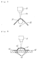
- Fig. 5 in which the marking area of the resin molding 21 is relatively wide, if the above marking method of holding a film 22 parallel to the surface of a resin molding 21 is employed, deflection is caused on the surface of the resin molding 21, and the contact between the film 22 and resin molding 21 is spoiled.
- a marking method as shown in Fig. 6 is possible.
- a film 23 having a thickness of about 75 microns is used.
- the film 23 is deflected and held in a U-form: with the applied side of a paint 24 outside, and the film 23 is pressed only to the marking position of the resin molding 21.
- the film 23 bent in a U-form maintains its U-form, and contacts with the surface of the molding 21, so that the surface of the paint 23 contacts appropriately with the surface of the molding 21.
- the surface of a resin molding 31 to be molded has a convex circle.
- the applied side of a paint 33 on this film 32 is placed to contact with the resin molding 31, and by pulling the film 32 from both sides with a proper force while maintaining this state, so that the film 32 can be contacted tightly to the surface of the circular resin molding 31 securely.
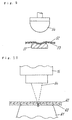
- the surface shape of a resin molding 41 is convex.
- a support stand 42 for positioning and holding the resin molding 41 has a plurality of through-pores 43.
- a film 45 is put on the resin molding 41 placed on the support stand 42 so that the applied side of a paint 44 may contact, and this covering film 45 is evacuated through the through-pores 43 on the outer circumference of the resin molding 41.
- a laser beam 14 is emitted.
- the film 45 can be contacted tightly to the resin molding 41 with a convex surface shape.
- the surface of a resin molding 51 has a concave shape.
- a paint 53 disposed to a film 52 contains an acrylic resin as an adhesive having a peelable tacky adhesiveness.
- the surface of the paint 53 of the film 52 is confronting, and the second surface at the opposite side of the film 52 is pressed by using an elastic piece 54 in a shape corresponding to the concave shape, and the film 52 and the paint 53 are adhered and held in the concave shape of the resin molding 51.
- the surface of the paint 53 can be securely contacted to the surface of the resin molding 51, and after finishing the marking, the film 52 can be easily peeled off.
- the marking method in Fig. 6 to Fig. 9 if the surface of the resin molding has a complicated shape such as spherical, convex, or concave shape or has an extremely wide area, the surface of the paint installed at one side of the film may be securely contacted to the surface of the molding.
- the paint fused by irradiation with laser beam is transferred and marked to the surface of the resin molding at an excellent precision.
- the laser beam is used, but not limited to this, any energy ray having a high energy such as electron beam, electron ray or heat ray capable of melting the paint can be used.
- Fig. 10 is an essential sectional view for explaining a marking method in a second embodiment of the invention.
- a sublimating paint 63 is disposed on one side of a PET colorless transparent film 61 which is a thermoplastic heat resistant resin.
- a YAG layer beam 64 capable of obtaining a short wavelength is used.
- the YAG laser beam is a beam generated from an apparatus using yttrium-aluminum-garnet material.
- the other method is same as in embodiment 1.
- a YAG laser beam 64 controlled by a deflector 15 completely penetrates through a film 62, and is concentrated and emitted to the dye 63 and the surface layer of the resin molding 61 beneath it.
- the sublimating dye 63 is vaporized, and the texture of the surface layer of the resin molding 61 is activated, and the vaporized dye 63 easily permeates into the surface layer of the molding.
- the dye 63 is disposed to the molding 61, and a mark is formed on the surface of the molding 61.
- the mark can be formed by permeating the vaporized dye 63 on the activated surface layer of the resin molding 61, so that the mark having an excellent wear resistance may be formed.
- the resin molding 61 is flat, but not limited to this shape, it may have complicated shapes as shown in Fig. 6 to Fig. 9, and the same contact is obtained as in embodiment 1, and the same effect as in embodiment 1 is obtained in this case.
- Fig. 11 shows an embodiment of a resin molding forming a mark by using a marking method of the invention, and it is a partial perspective view of a keyboard as an input device used in an electronic information appliance or the like.
- marks 72 are formed on the surface of key tops 71 which are a plurality of resin moldings of an operation unit.
- the key tops 71 is made of a thermoplastic resin excellent in processability, and marks 72 are formed on the operation surface.
- the marks 72 are formed by a method of emitting YAG laser beam by the same method as in embodiment 2, by using a plurality of films coated with sublimating dyes of different colors on one side.
- Paints of different colors are vaporized and permeate into the surface layer of the key tops 71, so that the plurality of marks 72 such as characters or patterns are clearly formed on the surface of the key tops 71 at high quality.
- the marks 72 have an excellent wear resistance.
- a colorless transparent film is used, but not limited to this, a colored translucent film may be used depending on the kind of the laser beam or the color of the applied paint.
- desired characters or patterns can be marked on the surface of the molding. Marks of various colors can be also formed. Moreover, the marks can be formed on the molding at lower cost. Marks having excellent wear resistance can be further formed. In addition, marks of excellent precision can be formed on the surface of the molding having complicated shape.
Landscapes
- Physics & Mathematics (AREA)
- Optics & Photonics (AREA)
- Thermal Transfer Or Thermal Recording In General (AREA)
- Application Of Or Painting With Fluid Materials (AREA)
- Dot-Matrix Printers And Others (AREA)
- Laser Beam Printer (AREA)
Applications Claiming Priority (2)
| Application Number | Priority Date | Filing Date | Title |
|---|---|---|---|
| JP34893697 | 1997-12-18 | ||
| JP9348936A JPH11180099A (ja) | 1997-12-18 | 1997-12-18 | マーキング方法およびマーク付樹脂成形体 |
Publications (2)
| Publication Number | Publication Date |
|---|---|
| EP0924096A1 true EP0924096A1 (fr) | 1999-06-23 |
| EP0924096B1 EP0924096B1 (fr) | 2004-03-17 |
Family
ID=18400389
Family Applications (1)
| Application Number | Title | Priority Date | Filing Date |
|---|---|---|---|
| EP98310164A Expired - Lifetime EP0924096B1 (fr) | 1997-12-18 | 1998-12-11 | Procédé de marquage utilisant des rayons actiniques et produit moulé marqué par ce procédé |
Country Status (5)
| Country | Link |
|---|---|
| US (2) | US6245397B1 (fr) |
| EP (1) | EP0924096B1 (fr) |
| JP (1) | JPH11180099A (fr) |
| CN (1) | CN1153674C (fr) |
| DE (1) | DE69822417T2 (fr) |
Cited By (3)
| Publication number | Priority date | Publication date | Assignee | Title |
|---|---|---|---|---|
| WO2005050292A1 (fr) * | 2003-11-21 | 2005-06-02 | Menicon Co., Ltd. | Procede de coloration de lentilles oculaires |
| EP2392471A4 (fr) * | 2009-01-27 | 2014-04-09 | Shizuoka Prefecture | Procédé de marquage au laser |
| JP2015182042A (ja) * | 2014-03-25 | 2015-10-22 | 日本バイリーン株式会社 | シート状部材の望む部分をマーキングする方法および装置 |
Families Citing this family (18)
| Publication number | Priority date | Publication date | Assignee | Title |
|---|---|---|---|---|
| US6575146B1 (en) | 1999-10-22 | 2003-06-10 | Toyota Jidosha Kabushiki Kaisha | Diagnostic apparatus for an evaporated fuel system, and vehicle control apparatus for a vehicle equipped with the diagnostic apparatus |
| JP2001256751A (ja) * | 2000-03-13 | 2001-09-21 | Sony Corp | シャッター及びこれを有するディスクカートリッジ |
| JP2003221257A (ja) * | 2002-01-31 | 2003-08-05 | Nippon Sheet Glass Co Ltd | 透明薄膜の成形方法およびそれを備える透明基体 |
| CN100343075C (zh) * | 2002-10-01 | 2007-10-17 | Nok株式会社 | 标记形成方法以及形成标记的成形品 |
| US20050003103A1 (en) * | 2003-04-29 | 2005-01-06 | Krupa Robert J. | Method for embedding a marking substance in a device such as an insertion tube |
| US7693855B2 (en) * | 2003-10-28 | 2010-04-06 | Media Cybernetics, Inc. | Method, system, and computer program product for managing data associated with a document stored in an electronic form |
| US8529775B2 (en) * | 2007-02-20 | 2013-09-10 | Revolaze, LLC | Decorative products created by lazing graphics and patterns directly on substrates with painted surfaces |
| JP5467670B2 (ja) * | 2008-03-31 | 2014-04-09 | 株式会社ニデック | 染色方法及び染色装置 |
| TWI371374B (en) * | 2009-09-14 | 2012-09-01 | Compal Electronics Inc | Production method of three dimensional pattern |
| JP6010349B2 (ja) * | 2011-06-09 | 2016-10-19 | 株式会社ニデック | 染色方法及び染色装置 |
| WO2013155659A1 (fr) | 2012-04-16 | 2013-10-24 | Rhodia Operations | Compositions fluoropolymères |
| CN103386820B (zh) * | 2013-07-02 | 2016-01-13 | 苏州威仕薄膜科技有限公司 | 一种太阳膜热转印打标机 |
| EP2886360B1 (fr) * | 2013-12-17 | 2016-07-20 | Braun GmbH | Procédé de marquage induit par laser d'un article |
| JP6623626B2 (ja) * | 2015-09-04 | 2019-12-25 | オムロン株式会社 | 転写方法 |
| CN105313481B (zh) * | 2015-11-23 | 2018-01-09 | 英诺激光科技股份有限公司 | 一种透明材料激光诱导湿法彩色打标装置及方法 |
| CN108778766B (zh) * | 2016-03-29 | 2021-12-31 | 科思创德国股份有限公司 | 用于对塑料件进行部分染色的方法 |
| CN110315860A (zh) * | 2018-03-31 | 2019-10-11 | 上海东震冶金工程技术有限公司 | 高温钢坯在线激光打标装置及其使用方法 |
| CN113197779B (zh) * | 2021-04-26 | 2022-10-04 | 佛山隆深机器人有限公司 | 一种西林瓶打标装置 |
Citations (3)
| Publication number | Priority date | Publication date | Assignee | Title |
|---|---|---|---|---|
| EP0201627A2 (fr) * | 1985-05-14 | 1986-11-20 | Bayer Ag | Procédé pour le marquage des matières macromoléculaires |
| EP0605803A1 (fr) * | 1992-12-12 | 1994-07-13 | Hoechst Aktiengesellschaft | Marquage en couleurs des surfaces en plastique par laser |
| WO1995013195A1 (fr) * | 1993-11-09 | 1995-05-18 | Markem Corporation | Support d'impression par transfert |
Family Cites Families (23)
| Publication number | Priority date | Publication date | Assignee | Title |
|---|---|---|---|---|
| US3964389A (en) * | 1974-01-17 | 1976-06-22 | Scott Paper Company | Printing plate by laser transfer |
| US3978247A (en) * | 1974-01-28 | 1976-08-31 | Rca Corporation | Transfer recording process |
| US4064205A (en) * | 1974-07-02 | 1977-12-20 | Logetronics, Inc. | Method for making a printing plate from a porous substrate |
| US4245003A (en) * | 1979-08-17 | 1981-01-13 | James River Graphics, Inc. | Coated transparent film for laser imaging |
| EP0113167A3 (fr) * | 1982-10-14 | 1986-06-18 | Autotype International Limited | Matériaux de formation d'images à l'aide du laser |
| JPS604094A (ja) | 1983-06-22 | 1985-01-10 | Daiichi Jitsugyo Kk | 表示キ−の加工方法 |
| JPS60262687A (ja) * | 1984-06-11 | 1985-12-26 | Daicel Chem Ind Ltd | レ−ザ−記録用フイルム |
| JPS6111771A (ja) | 1984-06-28 | 1986-01-20 | Hitachi Ltd | 画像記録装置 |
| JPS6259663A (ja) | 1985-09-09 | 1987-03-16 | Mitsubishi Kasei Vinyl Co | ビニル系樹脂組成物の製法 |
| USH158H (en) * | 1985-11-12 | 1986-11-04 | The United States Of America As Represented By The Secretary Of The Army | Method of bonding an electrically conductive material to an electrically conductive layer which overlies a curved non-metallic substrate |
| US4743463A (en) * | 1986-02-21 | 1988-05-10 | Eastman Kodak Company | Method for forming patterns on a substrate or support |
| DE3788284T3 (de) * | 1986-12-09 | 2000-10-12 | Polaroid Corp., Cambridge | Thermisches aufzeichnungsmittel. |
| JPH01267092A (ja) | 1988-04-19 | 1989-10-24 | Miyachi Electric Co | レーザマーキング方法 |
| WO1993003928A1 (fr) * | 1991-08-16 | 1993-03-04 | E.I. Du Pont De Nemours And Company | Moyens de formation d'images en ecriture directe par infrarouges |
| DE4232373A1 (de) * | 1992-09-03 | 1994-03-10 | Deutsche Forsch Luft Raumfahrt | Verfahren zum Auftragen strukturierter Schichten |
| JP2751089B2 (ja) | 1992-11-30 | 1998-05-18 | 大日本インキ化学工業株式会社 | レーザーマーキング方法及び印刷インキ |
| US5757313A (en) | 1993-11-09 | 1998-05-26 | Markem Corporation | Lacer-induced transfer printing medium and method |
| US5618370A (en) | 1994-05-25 | 1997-04-08 | Avery Dennison Corporation | Color applicator for laser printers and photocopiers |
| US5945249A (en) * | 1995-04-20 | 1999-08-31 | Imation Corp. | Laser absorbable photobleachable compositions |
| US5962181A (en) * | 1996-04-23 | 1999-10-05 | Agfa-Gevaert, N.V. | Process for the preparation of a metal heat mode recording element |
| JP4171933B2 (ja) * | 1997-09-12 | 2008-10-29 | ソニー株式会社 | 平面型レンズの製造方法 |
| US6121991A (en) * | 1998-06-23 | 2000-09-19 | Eastman Kodak Company | Forming authenticated images in a receiver |
| US6139661A (en) * | 1998-10-20 | 2000-10-31 | International Business Machines Corporation | Two step SMT method using masked cure |
-
1997
- 1997-12-18 JP JP9348936A patent/JPH11180099A/ja active Pending
-
1998
- 1998-12-11 EP EP98310164A patent/EP0924096B1/fr not_active Expired - Lifetime
- 1998-12-11 DE DE1998622417 patent/DE69822417T2/de not_active Expired - Fee Related
- 1998-12-14 US US09/210,984 patent/US6245397B1/en not_active Expired - Fee Related
- 1998-12-18 CN CNB981232299A patent/CN1153674C/zh not_active Expired - Fee Related
-
2001
- 2001-04-24 US US09/840,170 patent/US20020006475A1/en not_active Abandoned
Patent Citations (3)
| Publication number | Priority date | Publication date | Assignee | Title |
|---|---|---|---|---|
| EP0201627A2 (fr) * | 1985-05-14 | 1986-11-20 | Bayer Ag | Procédé pour le marquage des matières macromoléculaires |
| EP0605803A1 (fr) * | 1992-12-12 | 1994-07-13 | Hoechst Aktiengesellschaft | Marquage en couleurs des surfaces en plastique par laser |
| WO1995013195A1 (fr) * | 1993-11-09 | 1995-05-18 | Markem Corporation | Support d'impression par transfert |
Cited By (4)
| Publication number | Priority date | Publication date | Assignee | Title |
|---|---|---|---|---|
| WO2005050292A1 (fr) * | 2003-11-21 | 2005-06-02 | Menicon Co., Ltd. | Procede de coloration de lentilles oculaires |
| EP2392471A4 (fr) * | 2009-01-27 | 2014-04-09 | Shizuoka Prefecture | Procédé de marquage au laser |
| US9415463B2 (en) | 2009-01-27 | 2016-08-16 | Shizuoka Prefecture | Laser marking method |
| JP2015182042A (ja) * | 2014-03-25 | 2015-10-22 | 日本バイリーン株式会社 | シート状部材の望む部分をマーキングする方法および装置 |
Also Published As
| Publication number | Publication date |
|---|---|
| US6245397B1 (en) | 2001-06-12 |
| JPH11180099A (ja) | 1999-07-06 |
| US20020006475A1 (en) | 2002-01-17 |
| CN1220210A (zh) | 1999-06-23 |
| DE69822417T2 (de) | 2005-01-13 |
| DE69822417D1 (de) | 2004-04-22 |
| EP0924096B1 (fr) | 2004-03-17 |
| CN1153674C (zh) | 2004-06-16 |
Similar Documents
| Publication | Publication Date | Title |
|---|---|---|
| EP0924096A1 (fr) | Procédé de marquage utilisant des rayons actiniques et produit moulé marqué par ce procédé | |
| US5104719A (en) | Heat activated, quick release decals and associated methods | |
| JP2858513B2 (ja) | レーザー照射によるマーク形成方法および当該方法用エンボスホイル | |
| CA2454909C (fr) | Procede pour fabriquer une pellicule pouvant etre marquee au laser | |
| US4704310A (en) | Heat transferable laminate | |
| US4012552A (en) | Decorative metal film heat transfer decalcomania | |
| US4645556A (en) | Substrateless decorative embedded article and method of making | |
| JP7455818B2 (ja) | 装飾フィルム、転写フィルム、転写フィルムの使用、転写フィルムの製造方法、プラスチック成形品の装飾方法、およびプラスチック成形品 | |
| HK1006297B (en) | Process for decorating or marking a surface by means of laser radiation and use of a stamping foil in this process | |
| US4716052A (en) | Method of making pressure sensitive adhesive tag or label stock | |
| JPH0380429B2 (fr) | ||
| USRE39555E1 (en) | Cover sheet for impressing pattern on emblem | |
| US20240294033A1 (en) | Method for producing a plastic article, apparatus for carrying out said method, and plastic article | |
| JPH0866658A (ja) | 成形体内に図形を作製する方法 | |
| JP3295534B2 (ja) | レーザーマーキング用転写箔とこの転写箔を用いた絵柄付成形品の製造方法 | |
| US4313994A (en) | Heat transfer labeling | |
| JPH01157893A (ja) | 装飾方法 | |
| CA1245448A (fr) | Marquage des matieres plastiques | |
| JP3374290B2 (ja) | ホログラム箔付金属製品の印刷方法 | |
| JPH04307288A (ja) | 操作表示パネルの製造方法 | |
| JPH0825789A (ja) | 転写シート | |
| US20050069686A1 (en) | Composition comprising a substrate and image affixed thereto, process of preparation thereof, and assemblage of reaction products | |
| JP3463252B2 (ja) | 金属製品へのホットスタンプ印刷方法 | |
| JPH047194A (ja) | 電子部品の刻印処理方法 | |
| CA1064775A (fr) | Etiquetage par transfert thermique |
Legal Events
| Date | Code | Title | Description |
|---|---|---|---|
| PUAI | Public reference made under article 153(3) epc to a published international application that has entered the european phase |
Free format text: ORIGINAL CODE: 0009012 |
|
| AK | Designated contracting states |
Kind code of ref document: A1 Designated state(s): DE GB |
|
| AX | Request for extension of the european patent |
Free format text: AL;LT;LV;MK;RO;SI |
|
| 17P | Request for examination filed |
Effective date: 19991213 |
|
| AKX | Designation fees paid |
Free format text: DE GB |
|
| 17Q | First examination report despatched |
Effective date: 20020227 |
|
| GRAP | Despatch of communication of intention to grant a patent |
Free format text: ORIGINAL CODE: EPIDOSNIGR1 |
|
| GRAS | Grant fee paid |
Free format text: ORIGINAL CODE: EPIDOSNIGR3 |
|
| GRAA | (expected) grant |
Free format text: ORIGINAL CODE: 0009210 |
|
| AK | Designated contracting states |
Kind code of ref document: B1 Designated state(s): DE GB |
|
| REG | Reference to a national code |
Ref country code: GB Ref legal event code: FG4D |
|
| REF | Corresponds to: |
Ref document number: 69822417 Country of ref document: DE Date of ref document: 20040422 Kind code of ref document: P |
|
| PLBE | No opposition filed within time limit |
Free format text: ORIGINAL CODE: 0009261 |
|
| STAA | Information on the status of an ep patent application or granted ep patent |
Free format text: STATUS: NO OPPOSITION FILED WITHIN TIME LIMIT |
|
| 26N | No opposition filed |
Effective date: 20041220 |
|
| PGFP | Annual fee paid to national office [announced via postgrant information from national office to epo] |
Ref country code: GB Payment date: 20061206 Year of fee payment: 9 |
|
| GBPC | Gb: european patent ceased through non-payment of renewal fee |
Effective date: 20071211 |
|
| PG25 | Lapsed in a contracting state [announced via postgrant information from national office to epo] |
Ref country code: GB Free format text: LAPSE BECAUSE OF NON-PAYMENT OF DUE FEES Effective date: 20071211 |
|
| PGFP | Annual fee paid to national office [announced via postgrant information from national office to epo] |
Ref country code: DE Payment date: 20081205 Year of fee payment: 11 |
|
| PG25 | Lapsed in a contracting state [announced via postgrant information from national office to epo] |
Ref country code: DE Free format text: LAPSE BECAUSE OF NON-PAYMENT OF DUE FEES Effective date: 20100701 |