EP0925928A2 - Appareil et procédé d'enregistrement - Google Patents
Appareil et procédé d'enregistrement Download PDFInfo
- Publication number
- EP0925928A2 EP0925928A2 EP98310644A EP98310644A EP0925928A2 EP 0925928 A2 EP0925928 A2 EP 0925928A2 EP 98310644 A EP98310644 A EP 98310644A EP 98310644 A EP98310644 A EP 98310644A EP 0925928 A2 EP0925928 A2 EP 0925928A2
- Authority
- EP
- European Patent Office
- Prior art keywords
- recording
- ink
- ejection
- recording apparatus
- recording medium
- Prior art date
- Legal status (The legal status is an assumption and is not a legal conclusion. Google has not performed a legal analysis and makes no representation as to the accuracy of the status listed.)
- Granted
Links
- 238000000034 method Methods 0.000 title claims abstract description 12
- 238000012937 correction Methods 0.000 claims abstract description 31
- 230000008961 swelling Effects 0.000 claims description 18
- 238000001514 detection method Methods 0.000 claims description 14
- 238000012545 processing Methods 0.000 claims description 13
- 239000007788 liquid Substances 0.000 claims description 12
- 238000010438 heat treatment Methods 0.000 claims description 6
- 239000000976 ink Substances 0.000 description 125
- 239000000123 paper Substances 0.000 description 81
- 238000010586 diagram Methods 0.000 description 13
- 238000010276 construction Methods 0.000 description 11
- 230000001419 dependent effect Effects 0.000 description 11
- 230000003111 delayed effect Effects 0.000 description 8
- 230000007246 mechanism Effects 0.000 description 6
- 230000000694 effects Effects 0.000 description 5
- 238000012546 transfer Methods 0.000 description 5
- 230000001934 delay Effects 0.000 description 4
- 238000009835 boiling Methods 0.000 description 3
- 239000003086 colorant Substances 0.000 description 3
- 230000035515 penetration Effects 0.000 description 3
- 230000015572 biosynthetic process Effects 0.000 description 2
- 238000007641 inkjet printing Methods 0.000 description 2
- 238000012986 modification Methods 0.000 description 2
- 230000004048 modification Effects 0.000 description 2
- 238000007639 printing Methods 0.000 description 2
- 238000011084 recovery Methods 0.000 description 2
- 239000007787 solid Substances 0.000 description 2
- 230000005540 biological transmission Effects 0.000 description 1
- 238000004140 cleaning Methods 0.000 description 1
- 239000011248 coating agent Substances 0.000 description 1
- 238000000576 coating method Methods 0.000 description 1
- 239000000470 constituent Substances 0.000 description 1
- 230000007423 decrease Effects 0.000 description 1
- 238000001704 evaporation Methods 0.000 description 1
- 230000008020 evaporation Effects 0.000 description 1
- 238000002474 experimental method Methods 0.000 description 1
- 239000004744 fabric Substances 0.000 description 1
- 230000010365 information processing Effects 0.000 description 1
- 239000010985 leather Substances 0.000 description 1
- 230000008569 process Effects 0.000 description 1
- 230000004044 response Effects 0.000 description 1
- 230000000717 retained effect Effects 0.000 description 1
- 239000000126 substance Substances 0.000 description 1
- XLYOFNOQVPJJNP-UHFFFAOYSA-N water Substances O XLYOFNOQVPJJNP-UHFFFAOYSA-N 0.000 description 1
Images




Classifications
-
- B—PERFORMING OPERATIONS; TRANSPORTING
- B41—PRINTING; LINING MACHINES; TYPEWRITERS; STAMPS
- B41J—TYPEWRITERS; SELECTIVE PRINTING MECHANISMS, i.e. MECHANISMS PRINTING OTHERWISE THAN FROM A FORME; CORRECTION OF TYPOGRAPHICAL ERRORS
- B41J2/00—Typewriters or selective printing mechanisms characterised by the printing or marking process for which they are designed
- B41J2/005—Typewriters or selective printing mechanisms characterised by the printing or marking process for which they are designed characterised by bringing liquid or particles selectively into contact with a printing material
- B41J2/01—Ink jet
- B41J2/015—Ink jet characterised by the jet generation process
- B41J2/04—Ink jet characterised by the jet generation process generating single droplets or particles on demand
- B41J2/045—Ink jet characterised by the jet generation process generating single droplets or particles on demand by pressure, e.g. electromechanical transducers
- B41J2/04501—Control methods or devices therefor, e.g. driver circuits, control circuits
- B41J2/04505—Control methods or devices therefor, e.g. driver circuits, control circuits aiming at correcting alignment
-
- B—PERFORMING OPERATIONS; TRANSPORTING
- B41—PRINTING; LINING MACHINES; TYPEWRITERS; STAMPS
- B41J—TYPEWRITERS; SELECTIVE PRINTING MECHANISMS, i.e. MECHANISMS PRINTING OTHERWISE THAN FROM A FORME; CORRECTION OF TYPOGRAPHICAL ERRORS
- B41J2/00—Typewriters or selective printing mechanisms characterised by the printing or marking process for which they are designed
- B41J2/005—Typewriters or selective printing mechanisms characterised by the printing or marking process for which they are designed characterised by bringing liquid or particles selectively into contact with a printing material
- B41J2/01—Ink jet
- B41J2/015—Ink jet characterised by the jet generation process
- B41J2/04—Ink jet characterised by the jet generation process generating single droplets or particles on demand
- B41J2/045—Ink jet characterised by the jet generation process generating single droplets or particles on demand by pressure, e.g. electromechanical transducers
- B41J2/04501—Control methods or devices therefor, e.g. driver circuits, control circuits
- B41J2/04556—Control methods or devices therefor, e.g. driver circuits, control circuits detecting distance to paper
-
- B—PERFORMING OPERATIONS; TRANSPORTING
- B41—PRINTING; LINING MACHINES; TYPEWRITERS; STAMPS
- B41J—TYPEWRITERS; SELECTIVE PRINTING MECHANISMS, i.e. MECHANISMS PRINTING OTHERWISE THAN FROM A FORME; CORRECTION OF TYPOGRAPHICAL ERRORS
- B41J2/00—Typewriters or selective printing mechanisms characterised by the printing or marking process for which they are designed
- B41J2/005—Typewriters or selective printing mechanisms characterised by the printing or marking process for which they are designed characterised by bringing liquid or particles selectively into contact with a printing material
- B41J2/01—Ink jet
- B41J2/015—Ink jet characterised by the jet generation process
- B41J2/04—Ink jet characterised by the jet generation process generating single droplets or particles on demand
- B41J2/045—Ink jet characterised by the jet generation process generating single droplets or particles on demand by pressure, e.g. electromechanical transducers
- B41J2/04501—Control methods or devices therefor, e.g. driver circuits, control circuits
- B41J2/04573—Timing; Delays
-
- B—PERFORMING OPERATIONS; TRANSPORTING
- B41—PRINTING; LINING MACHINES; TYPEWRITERS; STAMPS
- B41J—TYPEWRITERS; SELECTIVE PRINTING MECHANISMS, i.e. MECHANISMS PRINTING OTHERWISE THAN FROM A FORME; CORRECTION OF TYPOGRAPHICAL ERRORS
- B41J2/00—Typewriters or selective printing mechanisms characterised by the printing or marking process for which they are designed
- B41J2/005—Typewriters or selective printing mechanisms characterised by the printing or marking process for which they are designed characterised by bringing liquid or particles selectively into contact with a printing material
- B41J2/01—Ink jet
- B41J2/015—Ink jet characterised by the jet generation process
- B41J2/04—Ink jet characterised by the jet generation process generating single droplets or particles on demand
- B41J2/045—Ink jet characterised by the jet generation process generating single droplets or particles on demand by pressure, e.g. electromechanical transducers
- B41J2/04501—Control methods or devices therefor, e.g. driver circuits, control circuits
- B41J2/0458—Control methods or devices therefor, e.g. driver circuits, control circuits controlling heads based on heating elements forming bubbles
-
- B—PERFORMING OPERATIONS; TRANSPORTING
- B41—PRINTING; LINING MACHINES; TYPEWRITERS; STAMPS
- B41J—TYPEWRITERS; SELECTIVE PRINTING MECHANISMS, i.e. MECHANISMS PRINTING OTHERWISE THAN FROM A FORME; CORRECTION OF TYPOGRAPHICAL ERRORS
- B41J29/00—Details of, or accessories for, typewriters or selective printing mechanisms not otherwise provided for
- B41J29/38—Drives, motors, controls or automatic cut-off devices for the entire printing mechanism
- B41J29/393—Devices for controlling or analysing the entire machine ; Controlling or analysing mechanical parameters involving printing of test patterns
Definitions
- the present invention relates to a recording apparatus and a recording method and more particularly to a recording apparatus and a recording method that performs recording on a recording medium by scanning the recording medium as ejecting ink from a recording head.
- a recording apparatus connected to a computer can record or print an image on paper according to image data generated by the computer.
- Various types of printer have been devised including a dot impact type, a heat transfer type and an electrophotography type.
- an inkjet type has prevailed.
- the inkjet printer achieves printing by ejecting ink from the recording head and therefore can print on recording mediums with unsatisfactory surface states including, for example, rough plain paper, leather and cloth as long as they can soak ink.
- a serial printer in particular which comprises, as its basic configuration, a paper feeding mechanism, a head scan mechanism, a motor drive circuit, a head drive circuit, a data processing/control circuit, an operation/display circuit and a power supply circuit, has a simple mechanism compared with a printer of electrophotography type such as LBP that is in wide use at offices.
- the serial inkjet printer is widely used in small offices and homes as a popular low-cost printer.
- Data entered from a computer into an input terminal is stored in a buffer of a signal processing circuit and converted into data corresponding to individual nozzles of the recording head.
- the converted data is transferred via a flexible cable to a head drive circuit on a carriage where it is converted into a signal for driving a heater of the recording head.
- the head drive circuit generates pulses in synchronism with the moving position of the carriage to eject ink
- the position of the carriage can be obtained from a signal that is produced by reading the output of a linear encoder extending along the scan direction of the carriage or from a drive pulse for a carriage driving pulse motor.
- a sheet of paper set in a paper supply unit is conveyed to the paper feeding mechanism.
- the recording head mounted on the carriage performs recording on the paper in a range corresponding to the head recording width.
- the paper feeding mechanism feeds forward the paper by a distance equal to the recording width. The scanning and paper feeding are repeated as far as the paper can be fed, after which the paper is discharged from a discharge port.
- serial inkjet printer is relatively simple in construction, because the recording head scans and performs recording for each line, any misregistration or misalignment between the lines will clearly show in the printed image. Because the inkjet printer in particular ejects ink droplets onto the paper, the paper swells with ink and expands in a direction of plane, causing dots near the joint between printed lines to be shifted out of alignment to a greater extent.
- the increased misalignment between the lines results from the fact that the recording is performed by ink droplets landing on the paper, ejected from the nozzles of the recording head.
- the ink droplets that have landed on the surface of paper penetrates into the interior of the paper where they are fixed. During this process, the water contained in the ink is soaked in the paper thereby swelling the paper. The swelling is not significant with films and paper with special coating. Plain paper such as copy paper swells easily.
- Our experiments show that when struck with 19.3 nl/mm 2 of ink, copy paper of one kind produced an elongation of about 0.51%.
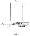
- the ejection timing of ink droplets has conventionally been controlled on the assumption that the distance between the nozzles of the recording head and the paper (hereinafter referred to as a paper-nozzle distance) is always constant and that the landing points on the surface of the recording medium are always determined by only the position of the nozzles. In reality, however, the ink landing point on the surface of the paper 2 does not coincide, for the reasons mentioned above, with the carriage position when the ink droplet is ejected, as shown in Figure 2.
- X represents the direction of scan and the arrow of broken line represents the locus of an ink droplet when recording is performed at the conventional ink ejection timing.
- the recording apparatus comprises a recording head for ejecting ink onto a recording medium, a scanning means for moving the recording head in a predetermined direction to scan the recording medium and a correction means for controlling an ejection timing of the ink according to a discrepancy information on the recording medium.
- the discrepancy information on the recording medium represents a deviation of a paper-nozzle distance from a reference value, the paper-nozzle distance representing a distance from a nozzle portion of the recording head to the opposing recording medium.
- the recording method ejects an ink on a recording medium, by using a recording head provided with an ejection portion for ejecting the ink, and scans the recording medium by the recording head to perform recording on the recording medium.
- the recording method comprises a step of obtaining a discrepancy information on a deviation of a distance from the ejection portion of the recoding head to the opposing recording medium, in a scan region of the recording head, and a step of controlling an ink ejection timing of the recording head according to the discrepancy information.
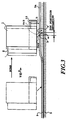
- FIG. 3 A main construction of the first embodiment of the invention is shown in Figure 3.
- the nozzles of a recording head 1 are arranged almost in the direction of paper feeding (Y direction) and eject ink droplets by producing bubbles in ink by a heater.
- Designated 2 is a sheet of paper, or a recording medium, which is generally a copying paper.
- a flat platen 3 provides a reference plane for maintaining the distance between the paper 2 and the recording head 1 at a fixed reference value. The reference value is a maximum distance between the nozzles of the recording head 1 and the opposing surface of the paper 2.
- the paper 2 is fed in the direction Y of Figure 3 by a feeding mechanism (not shown) to a position on the flat platen 3.
- a carriage 9 mounting the recording head 1 scans over the paper 2 (in the direction X) to perform recording on the paper 2.
- the carriage 9 has a paper-nozzle distance sensor 10 mounted ahead of the nozzles in the scan direction, which outputs a signal corresponding to the paper-nozzle distance to a control unit described later as the carriage 9 performs scanning.
- the paper-nozzle distance sensor 10 throws a laser beam L against the paper 2, detects the reflected light and outputs the DC signal that changes its level according to the distance between the paper and the nozzles of the recording head.
- the carriage 9 is driven by a drive motor (not shown) through a belt.
- the position of the carriage 9 in the direction X is obtained by a detection signal from an encoder, described later, which extends over the scan direction near the carriage 9.
- Figure 4 shows a block diagram of the first embodiment of the invention
- Figure 5 shows a timing diagram of signals at various portions of Figure 4.
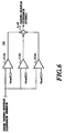
- a comparator/adder circuit 11 comprises three comparators 11a, 11b, 11c and an adder 11d, as shown in Figure 6. Reference voltages Vref1, Vref2, Vref3, each in different level, are supplied to these comparators, and compared with the DC detection signal from the paper-nozzle distance sensor 10 to produce a paper-nozzle distance signal (Fig. 5) in the comparator/adder circuit 11.
- the value of n varies according to a discrepancy information, which represents the difference between the paper-nozzle distance detected and the reference value.
- a timing generation circuit 16 generates a latch signal upon receiving the detection signal from the encoder 13.
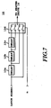
- Figure 7 shows one illustrative configuration of the delay circuit 15.
- the delay circuit 15 is composed of three delay circuits or delay circuits 15a, 15b, and 15c, the each delay circuit delays its input signal by a predetermined delay time t before outputting it.
- the output of each delay circuit is supplied to an analog switch 15d, which selects one of the inputs according to the value of n to output to a heater drive circuit 14.
- the heater drive circuit 14 drives the recording head 1 according to the recording data entered from a recording data interface 18 into a transfer circuit 17. The driving of the head is performed in synchronism with the heater drive timing signal.
- the encoder detection signal is processed as described above with a delay of a predetermined number of pulses corresponding to the deviation amount.
- the delay time for the ink droplet ejection timing is changed according to the deviation of the paper-nozzle distance from the reference value as described above, the deviation of the ink droplet from the intended landing position can be corrected.
- the ink droplet which is ejected when the carriage 9 is at position 9a and is originally intended to follow a trace Tr1 to land at position a, would undesirably land at position b if the paper were cockled as shown at 2a.
- the ejection timing delay processing as described above can correct the droplet flying route to a trace Tr2, causing the droplet to land on the cockled paper at position a'. Therefore, the droplet landing position on the surface of the paper 2 can be corrected in the scan direction at all times, producing an image with little dot position deviation.
- the invention is also very effective in a full line type inkjet printer to correct the dot position deviation in the scan direction according to changes in the paper-nozzle distance.
- Other embodiments are also effective for both of the serial type and the full line type inkjet printer.
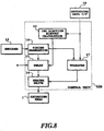
- FIG. 8 is a block diagram of a second embodiment of the invention.
- the block configuration of this embodiment is similar to that of the first embodiment, except that a control unit 12a does not have a paper-nozzle distance sensor and a comparator/adder circuit but instead includes an ink ejection history calculation section 19.
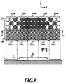
- the ink ejection history calculation section 19 calculates an ink ejection history based on recording data supplied from the recording data interface 18 . That is, the recording data for one scan is divided for a plurality of unit-area regions 23a, 23b, 23c, 23d, 23e, as shown in Figure 9, and the ink ejection history calculation section 19 counts the number of ink droplets ejected onto each region and outputs the count value.
- the ink ejection history calculation section 19 can include a latch, a dot counter and an adder circuit.
- the delay circuit 15 delays the latch signal from the timing generation circuit 16 according to the count value, and outputs the delayed signal as a heater drive timing signal. The delayed timing signal corrects the ejection timing in the next scan line.
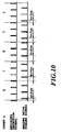
- Figure 10 is a timing diagram showing signals at various parts of Figure 8, which correspond to the recording data for the line 23 in Figure 9.
- Figure 9 shows each region as 3 ⁇ 3 dots for simplicity, another size can be used for the region.
- Black circles in the line 23 represent dot positions at which ink droplets were adhered and blank circles represent dot positions at which were not.
- Hatched circles in a line 24, which is to be scanned next, represent dot positions where ink droplets will adhere when ink droplets are ejected onto the surface of the paper 2 on the flat platen 3, that is swelled by the previously scanned line 23, as shown at 2a. This ink droplet ejection is corrected its ejection timing.
- the count value n (Fig. 10) is 3 for the region 23a, 7 for the region 23b, 9 for the region 23c, 7 for the region 23d, and 3 for the region 23e.
- the delay circuit 15 can be constructed of a plurality of delay circuits and an analog switch with inputs numbering one more than the delay circuits in the same way as the delay circuit 15 in Figure 4.
- the delay time of each delay circuit is set to ⁇ t.
- the coefficient ⁇ is the one whose value varies dependent on the kind of paper. The value of ⁇ increases as the paper becomes more likely to be swelled.
- the coefficient ⁇ optimally corrects the ejection timing according to the kind of paper to offset differences among different kinds of paper in the amount of cockling caused by the same amount of ink.
- the ⁇ value is set larger than that of the dedicated inkjet printing paper.
- the scale of hardware increases as the count value increases.
- the configuration may be modified to allow the calculation processing to be performed in such a way that the delay time is T+n ⁇ t where n is the count value.
- an encoder detection signal (Fig. 10) is delayed by T+3 ⁇ t according to the count value of 3 to produce the heater drive timing signal (Fig. 10).
- the encoder detection signal is delayed by T+7 ⁇ t, T+9 ⁇ t, T+7 ⁇ t and T+3 ⁇ t, respectively, according to the count values, i.e., by the length of time corresponding to the number of ink droplets ejected one line before, to produce the heater drive timing signals, according to which the heater drive circuit 14 drives the recording head 1.
- the ink droplet landing positions can be corrected for the regions 24a, 24b, 24c, 25d, 24e in the next adjacent line 24 as shown in Figure 9, thereby producing an image without dot position deviations.
- the dot positions in the regions 24b, 24d of the line 24 appear more uneven than those in other regions 24a, 24c, 24e. This is because the regions 24b, 24d are represented larger in area, for the sake of simplicity, than they actually are, although the paper 2 is inclined in these regions 24b, 24d (there are unequalities in the paper-nozzle distance), so that the amount of correction in the regions concerned appears constant (whereas the amount of correction actually depends on the paper-nozzle distance).
- the uneven distribution of the dot positions, as seen in the inclined portions in Figure 9 will pose no practical problem.
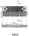
- the dot position misalignment will occur in the line 24 of Figure 11 when compared with the ejection history of the previous scan (line 23) similar to the one shown in Figure 9.
- the position deviation is particularly conspicuous as the paper is swelled at 2a.
- the dot position deviation is almost proportional to the amount of cockling of the paper 2.
- the number of ink droplets ejected one line before is used as the discrepancy information, representing the deviation of the paper-nozzle distance from the reference value.
- the amount of cockling at the A-A' position in the next line 24 in Figure 9 is estimated to perform the delay control on the ink ejection timing. It is therefore possible to correct the ink landing positions on the paper surface and eliminate the position misalignment as shown in Figure 11, thereby producing an image without any dot position deviations.
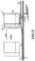
- the main construction of the third embodiment of the invention is shown in Figure 12.
- the main construction of this embodiment is similar to that of the first embodiment, except that the carriage 9 is not provided with the paper-nozzle distance sensor 10.
- the third embodiment has the construction similar to that (not shown) of the second embodiment.
- the ejection timing can be corrected irrespective of performance of the detection precision of the paper-nozzle distance sensor, and the carriage scanning speed can be increased faster.
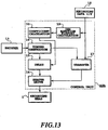
- Figure 13 is a block diagram showing the third embodiment of the invention.
- the block configuration of this recording apparatus (printer) of the third embodiment is similar to that of the first embodiment, except that a control unit 12b is not provided with a comparator/adder circuit but instead includes the ink ejection history calculation section 19 and a coefficient calculation section 20.
- the third embodiment has the head configuration of the second embodiment without the paper-nozzle distance sensor, but with the coefficient calculation section 20 added.
- Signals at various parts of Figure 13 that correspond to the recording data for the line 23 in Figure 9 are similar to those shown in Figure 10.
- the detection signal (Fig. 10) from the encoder 13 is sent to the control unit 12 b.
- the timing generation circuit 16 generates the latch signal according to the detection signal from the encoder 13.
- the operations and configurations of the heater drive circuit 14, the transfer circuit 17, the recording data interface 18, the ink ejection history calculation section 19 and the recording head 1 are as explained above, and their descriptions are omitted here.
- the coefficient calculation section 20 computes the coefficient ⁇ that represents a parameter affecting the formation of cockling and gives the computed coefficient to the delay circuit 15. That is, the coefficient ⁇ , which is supplied from outside the control unit in the second embodiment, is calculated inside the control unit 12b in this embodiment.
- the delay circuit 15 outputs the heater drive timing signal that is produced by delaying the latch signal from the timing generation circuit 16 according to the count value n and the coefficient ⁇ . The delayed timing signal thus produced is used to correct the ink ejection timing during the next scan, in the same manner as the second embodiment. How the correction is carried out is shown in Figure 9 as in the second embodiment, and its detailed explanation is omitted here.
- the hardware scale increases as the count value increases, as is the case with the second embodiment.
- the calculation processing may count a number proportional to the number of ink droplets so that the delay time will be T+n ⁇ t where n is the count value.
- the third embodiment uses the number of ink droplets ejected one line before (ejection event history) as the discrepancy information, in a similar way to the second embodiment, representing the deviation of the paper-nozzle distance from the reference value and, based on the number of ejected ink droplets, estimates the amount of cockling in the A-A' position of the next line 24 in Figure 9 to perform the delay control on the ejection timing.
- This delay control is so configured as to calculate and use the coefficient ⁇ that represents a parameter affecting the formation of cockling. It is therefore possible to correct the ink landing positions on the paper surface and eliminate the position misalignment as shown in Figure 11 to produce an image without dot position deviations.
- the recording head scans over the same region of the paper two or more times, the recording is more susceptible to the cockling caused by the previous scan.
- the second and third embodiments can effectively be applied not only to a single-pass recording but to the multi-pass recording.
- these embodiments are particularly effective in aligning the dots of different colors in the direction of paper feeding.
- the fourth embodiment can be applied to a recording apparatus in which a plurality of recording heads are arranged side by side at predetermined intervals in the direction of scan, and performs correction similar to that of the second embodiment on the individual recording heads in the scan direction.
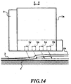
- FIG 14 shows the main construction of the fourth embodiment.
- a recording head 1a mounted on the carriage 9 is for color printing.
- the recording head 1a has mounted therein at equal intervals, a recording head 1b for black ink, a recording head 1c for cyan ink, a recording head 1m for magenta ink and a recording head 1y for yellow ink, from the ahead toward the behind in the scan direction X.
- the nozzles of each recording head are arranged in the same direction as the paper feeding direction Y.
- the recording head 1b first ejects black ink, after which the recording head 1c ejects cyan ink so that the cyan ink droplets land on the black ink dots. Then at the same positions as the first black ink dots, ink droplets of different colors are landed successively (overlay ejecting) to form a color image.
- the paper 2 is swelled as shown at 2a dependent on the amount of inks already ejected from the recording heads located on the ahead side in the scan direction X.
- a control unit is formed in the similar configuration to the one shown in Figure 8 and provided with an ink ejection history calculation section.
- the ink ejection history calculation section counts the number of ink droplets ejected onto the unit area of the paper 2 from other recording heads located to the ahead, in the scan direction, of each recording head. Further, according to the counting result, the ejection timing of each recording head is delayed to correct the landing positions.
- the ejection timing of the recording head 1c is delayed by a length of time corresponding to the total number of ink droplets ejected from the recording head 1b onto the unit area.
- the ejection timing of the recording head 1m is delayed by a length of time that corresponding to the sum of the number of ink droplets ejected from the recording head 1b onto the unit area and the number of ink droplets ejected from the recording head 1c onto the same unit area. In this way, the landing positions of ink droplets are corrected.
- These recording heads are not limited to the recording heads for different color inks but may include those for processing liquids. Two or more recording heads of the same color may also be used.
- this embodiment uses the number of ink droplets (ejection event history), as the discrepancy information that represents the deviation of the paper-nozzle distance from the reference value, which are ejected onto the unit area of the paper.
- the above ejection onto the unit area is performed by the recording head located ahead of other recording heads in the scan direction, of the plurality of recording heads.
- the amount of cockling is estimated before the succeeding ink droplets are ejected overlying the preceding dots to perform the delay control on the ejection timing.
- deviations of the landing positions on paper surface of dots ejected from each recording head can be corrected during one scan.
- This correction performed during one scan may be combined with the correction that is performed, between the lines in the second embodiment. Further, rather than counting the number of ink droplets, the second to fourth embodiments may be modified to compute the amount of ink ejected onto the unit area as the ink ejection event history.
- the coefficient ⁇ used in the second and third embodiments varies in value dependent only on the kind of the paper used.
- a coefficient ⁇ ' is used, which includes another parameter in addition to the aforementioned coefficient ⁇ . That is, the fifth embodiment can set, as a correction coefficient of a medium property, a coefficient ⁇ ' which includes a coefficient ( ⁇ 1) dependent on the kind of ink in addition to the coefficient ⁇ . For example, for an ink with a low penetration capability, ⁇ 1 is set to ⁇ 1 ⁇ 1 because the low penetration ink is unlikely to cause swelling; and for another ink with a high penetration capability, ⁇ 1 is set to ⁇ 1>1.
- the coefficient setting that includes the coefficient ( ⁇ 2) dependent on head scan speed is effective because the swelling proceeds immediately after the ink droplets ejected from the adjoining head adhere to the paper.
- the swelling initiated by the ink ejected from the adjacent head does not proceed greatly, and thus ⁇ 2 is set to ⁇ 2 ⁇ 1.
- the swelling initiated by the ink ejected from the adjacent head proceeds significantly, and the coefficient ⁇ 2 is set to ⁇ 2>1.
- the coefficient setting that includes the coefficient( ⁇ 3) dependent on the head scan time interval as an additional factor is effective, whatever the head configuration may be. If the scan time interval is short, the swelling will not easily proceed and thus the coefficient ⁇ 3 may be set to ⁇ 3 ⁇ 1; and if the scan time interval is long, the swelling will easily proceed and ⁇ 3 may be set to ⁇ 3>1.
- this embodiment can set another coefficient ⁇ ' that includes a coefficient ( ⁇ 4) dependent on the ambient temperature in addition to the above coefficient ⁇ , and also another coefficient ⁇ ' that includes a coefficient ( ⁇ 5) dependent on the ambient humidity in addition to the coefficient ⁇ .
- the coefficient ( ⁇ 4) dependent on the ambient temperature when the ambient temperature is high, the coefficient is set at ⁇ 4 ⁇ 1 because at high temperature the paper itself is elongated and the soaked ink is easily dried. When the ambient temperature is low, the paper itself is shrunk and the ink is not easily dried, so that it is set to ⁇ 4>1.
- the coefficient ( ⁇ 5) that depends on the ambient humidity is used and when the ambient humidity is high, the paper itself is swelled and the degree of swelling caused by ink is small, so that the coefficient ⁇ 5 may be set to ⁇ 5 ⁇ 1.
- the degree of swelling by ink is large, so that ⁇ 5 is set to ⁇ 5>1.
- Preset values for the parameters are used to calculate the coefficient ⁇ ', which is then sent to the delay circuit 15.
- these parameters can be reflected on the delay time.
- Figure 15 shows a block configuration of the sixth embodiment.
- the block configuration of the recording apparatus of this embodiment is almost similar to that of the second embodiment, except that a control unit 12c is not provided with the ink ejection history calculation section but includes a recording speed calculation section 30.
- the head scan time interval is calculated based on the recording data and, according to this scan time interval obtained, the degree to which the cockling has progressed is estimated.
- the recording speed calculation section 30 calculates the recording speed as described below by using the recording data supplied from the recording data interface 18.
- the transfer circuit 17 takes time for processing the signals of the large-capacity recording data, so that the time internal between the previous scan and the next scan is long, lowering the recording speed.
- the recording speed calculation section 30 calculates the amount of recording data for each scan and, based on the calculated data amount, determines the recording speed.
- the recording speed calculation section 30, after calculating the recording data amount for each scan, then calculates the signal processing time.
- the signal processing time is the time which elapses from a moment when the recording data for the previous scan is processed by the transfer circuit 17 and supplied to the recording head 1 to a moment when the recording data for the next scan is supplied to the recording head 1.
- the processing time is long (i.e., the scan time interval is long)
- the swelling of paper caused by ink progresses greatly and the ejection timing is corrected to extend the delay time.
- the processing time is short (i.e., the scan time interval is short)
- the swelling by the ink ejected previously does not proceed greatly and the ejection timing is corrected to shorten the delay time.
- the scan time interval ejection event history
- the discrepancy information which represents the deviation of the paper-nozzle distance (distance between the nozzle portion of the recording head and the opposing paper) from the reference value
- discrepancy information is generated in the recording apparatus
- a variety of the discrepancy information used in the above embodiments may be generated from the recording data in the host computer, which is externally connected to the recording apparatus, and the generated discrepancy information may be supplied to the recording apparatus along with the recording data.
- the present invention achieves distinct effect when applied to a recording head or a recording apparatus which has means for generating thermal energy such as electrothermal transducers or laser light, and which causes changes in ink by the thermal energy so as to eject ink. This is because such a system can achieve a high density and high resolution recording.
- the on-demand type apparatus has electrothermal transducers, each disposed on a sheet or liquid passage that retains liquid (ink), and operates as follows: first, one or more drive signals are applied to the electrothermal transducers to cause thermal energy corresponding to recording information; second, the thermal energy induces sudden temperature rise that exceeds the nucleate boiling so as to cause the film boiling on heating portions of the recording head; and third, bubbles are grown in the liquid (ink) corresponding to the drive signals. By using the growth and collapse of the bubbles, the ink is expelled from at least one of the ink ejection orifices of the head to form one or more ink drops.
- the drive signal in the form of a pulse is preferable because the growth and collapse of the bubbles can be achieved instantaneously and suitably by this form of drive signal.
- a drive signal in the form of a pulse those described in U.S. patent Nos. 4,463,359 and 4,345,262 are preferable.
- the rate of temperature rise of the heating portions described in U.S. patent No. 4,313,124 be adopted to achieve better recording.
- U.S. patent Nos. 4,558,333 and 4,459,600 disclose the following structure of a recording head, which is incorporated to the present invention: this structure includes heating portions disposed on bent portions in addition to a combination of the ejection orifices, liquid passages and the electrothermal transducers disclosed in the above patents. Moreover, the present invention can he applied to structures disclosed in Japanese Patent Application Laying-open Nos. 59-123670 (1984) and 59-138461 (1984) in order to achieve similar effects.
- the former discloses a structure in which a slit common to all the electrothermal transducers is used as ejection orifices of the electrothermal transducers, and the latter discloses a structure in which openings for absorbing pressure waves caused by thermal energy are formed corresponding to the ejection orifices.
- the present invention can be also applied to a so-called full-line type recording head whose length equals the maximum length across a recording medium.
- a recording head may consists of a plurality of recording heads combined together, or one integrally arranged recording head.
- the, present invention can be applied to various serial type recording heads: a recording head fixed to the main assembly of a recording apparatus; a conveniently replaceable chip type recording head which, when loaded on the main assembly of a recording apparatus, is electrically connected to the main assembly, and is supplied with ink therefrom; and a cartridge type recording head integrally including an ink reservoir.
- a recovery system or a preliminary auxiliary system for a recording head as a constituent of the recording apparatus because they serve to make the effect of the present invention more reliable.
- the recovery system are a capping means and a cleaning means for the recording head, and a pressure or suction means for the recording head.
- the preliminary auxiliary system are a preliminary heating means utilizing electrothermal transducers or a combination of other heater elements and the electrothermal transducers, and a means for carrying out preliminary ejection of ink independently of the ejection for recording. These systems are effective for reliable recording.
- the number and type of recording heads to be mounted on a recording apparatus can be also changed. For example, only one recording head corresponding to a single color ink, or a plurality of recording heads corresponding to a plurality of inks different in color or concentration can be used.
- the present invention can be effectively applied to an apparatus having at least one of the monochromatic, multi-color and full-color modes.
- the monochromatic mode performs recording by using only one major color such as black.
- the multi-color mode carries out recording by using different color inks, and the full-color mode performs recording by color mixing.
- inks that are liquid when the recording signal is applied can be used: for example, inks can be employed that solidify at a temperature lower than the room temperature and are softened or liquefied in the room temperature. This is because in the inkjet system, the ink is generally temperature adjusted in a range of 30 °C-70 °C so that the viscosity of the ink is maintained at such a value that the ink can be ejected reliably.
- the present invention can be applied to such apparatus where the ink is liquefied just before the ejection by the thermal energy as follows so that the ink is expelled from the orifices in the liquid state, and then begins to solidify on hitting the recording medium, thereby preventing the ink evaporation: the ink is transformed from solid to liquid state by positively utilizing the thermal energy which would otherwise cause the temperature rise; or the ink, which is dry when left in air, is liquefied in response to the thermal energy of the recording signal.
- the ink may be retained in recesses or through holes formed in a porous sheet as liquid or solid substances so that the ink faces the electrothermal transducers as described in Japanese Patent Application Laying-open Nos: 54-56847 (1979) or 60-71260 (1985).
- the present invention is most effective when it uses the film boiling phenomenon to expel the ink.
- the inkjet recording apparatus of the present invention can be employed not only as an image output terminal of an information processing device such as a computer, but also as an output device of a copying machine including a reader, and as an output device of a facsimile apparatus having a transmission and receiving function.
Landscapes
- Ink Jet (AREA)
- Particle Formation And Scattering Control In Inkjet Printers (AREA)
Applications Claiming Priority (4)
| Application Number | Priority Date | Filing Date | Title |
|---|---|---|---|
| JP36150397 | 1997-12-26 | ||
| JP36150397 | 1997-12-26 | ||
| JP10356583A JPH11240146A (ja) | 1997-12-26 | 1998-12-15 | 記録装置 |
| JP35658398 | 1998-12-15 |
Publications (3)
| Publication Number | Publication Date |
|---|---|
| EP0925928A2 true EP0925928A2 (fr) | 1999-06-30 |
| EP0925928A3 EP0925928A3 (fr) | 2000-01-26 |
| EP0925928B1 EP0925928B1 (fr) | 2005-08-24 |
Family
ID=26580463
Family Applications (1)
| Application Number | Title | Priority Date | Filing Date |
|---|---|---|---|
| EP98310644A Expired - Lifetime EP0925928B1 (fr) | 1997-12-26 | 1998-12-23 | Appareil et procédé d'enregistrement |
Country Status (4)
| Country | Link |
|---|---|
| US (1) | US6471315B1 (fr) |
| EP (1) | EP0925928B1 (fr) |
| JP (1) | JPH11240146A (fr) |
| DE (1) | DE69831306T2 (fr) |
Cited By (12)
| Publication number | Priority date | Publication date | Assignee | Title |
|---|---|---|---|---|
| EP1287989A1 (fr) * | 2001-08-28 | 2003-03-05 | Hewlett-Packard Company, A Delaware Corporation | Variations de distance entre la tête d'impression et le support d'impression le long de l'axe de balayage, mesurées par senseur attaché au chariot |
| US6557961B2 (en) | 2001-06-22 | 2003-05-06 | Canon Kabushiki Kaisha | Variable ink firing frequency to compensate for paper cockling |
| US6604803B1 (en) | 2000-09-12 | 2003-08-12 | Canon Kabushiki Kaisha | Printer which compensates for paper unevenness |
| EP1164023A3 (fr) * | 2000-06-16 | 2003-08-20 | Canon Kabushiki Kaisha | Appareil d'enregistrement à jet d'encre utilisant un élément semi-conducteur solide |
| WO2003076190A1 (fr) * | 2002-03-14 | 2003-09-18 | Seiko Epson Corporation | Imprimante, procede d'impression, programme, support de stockage et systeme informatique |
| AU2002318771B2 (en) * | 2000-11-20 | 2004-08-05 | Presstek, Inc | Method and apparatus for optimized image processing |
| US6796628B2 (en) * | 2002-11-07 | 2004-09-28 | Pitney Bowes Inc. | Contour correcting printer |
| DE102005060785A1 (de) * | 2005-12-16 | 2007-06-28 | Man Roland Druckmaschinen Ag | Verfahren zum Betreiben einer Inkjet-Druckeinrichtung |
| EP1745930A3 (fr) * | 2005-07-22 | 2007-12-19 | Pitney Bowes, Inc. | Méthode et système de correction de distortion d'une image à imprimer due à la topographie irrégulière de l'espace d'impression de l'image |
| GB2491868A (en) * | 2011-06-15 | 2012-12-19 | Inca Digital Printers Ltd | Print gap compensation |
| US8465117B2 (en) | 2010-01-19 | 2013-06-18 | Seiko Epson Corporation | Fluid ejecting apparatus and fluid ejecting method |
| EP3573833A4 (fr) * | 2017-01-27 | 2020-09-09 | Hewlett-Packard Development Company, L.P. | Commande d'éjection de gouttes de fluide d'impression |
Families Citing this family (45)
| Publication number | Priority date | Publication date | Assignee | Title |
|---|---|---|---|---|
| US7237858B2 (en) | 2002-03-14 | 2007-07-03 | Seiko Epson Corporation | Printing apparatus, printing method, storage medium, and computer system |
| US6612673B1 (en) * | 2002-04-29 | 2003-09-02 | Hewlett-Packard Development Company, L.P. | System and method for predicting dynamic thermal conditions of an inkjet printing system |
| US7267419B2 (en) * | 2003-09-03 | 2007-09-11 | Seiko Epson Corporation | Method for liquid ejection and liquid ejecting apparatus |
| EP1529649A1 (fr) * | 2003-10-31 | 2005-05-11 | Hewlett-Packard Development Company, L.P. | Système de détection de la position d'un imprimé |
| US7360853B2 (en) | 2004-03-04 | 2008-04-22 | Fujifilm Dimatix, Inc. | Morphology-corrected printing |
| US8488184B2 (en) * | 2004-03-18 | 2013-07-16 | Riso Kagaku Corporation | Image forming apparatus having a plurality of individually controlled recording heads |
| US8085428B2 (en) * | 2004-10-15 | 2011-12-27 | Fujifilm Dimatix, Inc. | Print systems and techniques |
| US7911625B2 (en) * | 2004-10-15 | 2011-03-22 | Fujifilm Dimatrix, Inc. | Printing system software architecture |
| US8068245B2 (en) * | 2004-10-15 | 2011-11-29 | Fujifilm Dimatix, Inc. | Printing device communication protocol |
| US8199342B2 (en) * | 2004-10-29 | 2012-06-12 | Fujifilm Dimatix, Inc. | Tailoring image data packets to properties of print heads |
| JP4643279B2 (ja) * | 2005-01-25 | 2011-03-02 | 東芝テック株式会社 | インクジェット記録装置 |
| JP2006264074A (ja) * | 2005-03-23 | 2006-10-05 | Fuji Xerox Co Ltd | 液滴吐出装置 |
| US20070206038A1 (en) * | 2006-03-03 | 2007-09-06 | Richard Baker | Ink jet printing with multiple conveyors |
| KR20080067937A (ko) * | 2007-01-17 | 2008-07-22 | 삼성전자주식회사 | 화상형성장치 및 그 잉크분사방법 |
| JP2008246879A (ja) * | 2007-03-30 | 2008-10-16 | Brother Ind Ltd | 画像記録装置 |
| JP5504630B2 (ja) | 2008-03-25 | 2014-05-28 | セイコーエプソン株式会社 | 記録方法及び記録装置 |
| JP2009255523A (ja) | 2008-03-25 | 2009-11-05 | Seiko Epson Corp | 記録方法 |
| JP5485987B2 (ja) | 2008-06-06 | 2014-05-07 | フジフィルム ディマティックス, インコーポレイテッド | 印刷のための物体検出 |
| JP5596913B2 (ja) * | 2008-09-08 | 2014-09-24 | キヤノン株式会社 | 画像処理装置および画像処理方法 |
| JP5312122B2 (ja) | 2009-03-19 | 2013-10-09 | キヤノン株式会社 | インクジェット記録装置 |
| JP2011136518A (ja) * | 2009-12-29 | 2011-07-14 | Seiko Epson Corp | 液体吐出装置、及び、液体吐出方法 |
| JP2011156733A (ja) * | 2010-01-29 | 2011-08-18 | Canon Inc | インクジェット記録装置および記録位置調整方法 |
| GB2480806B (en) * | 2010-05-27 | 2016-01-06 | Inca Digital Printers Ltd | Printing method and apparatus |
| JP5648376B2 (ja) | 2010-08-31 | 2015-01-07 | ブラザー工業株式会社 | 液体吐出装置 |
| JP4857389B2 (ja) * | 2010-11-05 | 2012-01-18 | 東芝テック株式会社 | インクジェット記録装置 |
| JP6032003B2 (ja) * | 2012-03-30 | 2016-11-24 | ブラザー工業株式会社 | インクジェットプリンタ、インクジェットプリンタのギャップ情報取得方法、及び、液体吐出装置 |
| JP6210213B2 (ja) | 2012-12-17 | 2017-10-11 | ブラザー工業株式会社 | 液体吐出装置、液体吐出方法及び記録媒体 |
| JP6070209B2 (ja) | 2013-01-18 | 2017-02-01 | ブラザー工業株式会社 | インクジェット記録装置 |
| JP6186992B2 (ja) | 2013-07-29 | 2017-08-30 | ブラザー工業株式会社 | インクジェット記録装置 |
| JP6296326B2 (ja) | 2013-07-29 | 2018-03-20 | ブラザー工業株式会社 | インクジェット記録装置 |
| JP6187275B2 (ja) | 2014-01-20 | 2017-08-30 | ブラザー工業株式会社 | インクジェット記録装置、用紙判別装置、及びインクジェット記録方法 |
| JP6422267B2 (ja) | 2014-08-25 | 2018-11-14 | キヤノン株式会社 | インクジェット記録装置、インクジェット記録方法およびプログラム |
| JP6528492B2 (ja) * | 2015-03-23 | 2019-06-12 | セイコーエプソン株式会社 | 液体噴射装置 |
| US10011124B2 (en) | 2015-05-27 | 2018-07-03 | Canon Kabushiki Kaisha | Performing marginless printing based on image data |
| EP3098083B1 (fr) | 2015-05-27 | 2021-08-25 | Canon Kabushiki Kaisha | Appareil d'impression et platine |
| US10183505B2 (en) | 2015-05-27 | 2019-01-22 | Canon Kabushiki Kaisha | Printing apparatus and platen |
| JP6584146B2 (ja) | 2015-05-27 | 2019-10-02 | キヤノン株式会社 | プリント装置 |
| JP6610179B2 (ja) * | 2015-11-09 | 2019-11-27 | ブラザー工業株式会社 | 液滴吐出装置 |
| JP6641975B2 (ja) * | 2015-12-18 | 2020-02-05 | ブラザー工業株式会社 | 液体吐出装置 |
| DE102016124255A1 (de) * | 2016-12-13 | 2018-06-14 | Océ Holding B.V. | Verfahren zur Verbesserung der Druckqualität eines Tintendruckgeräts |
| JP6881359B2 (ja) * | 2018-03-14 | 2021-06-02 | ブラザー工業株式会社 | 印刷装置 |
| JP7171306B2 (ja) | 2018-08-10 | 2022-11-15 | キヤノン株式会社 | 液体吐出装置 |
| JP7293724B2 (ja) * | 2019-02-28 | 2023-06-20 | セイコーエプソン株式会社 | 印刷装置および印刷調整方法 |
| JP7518678B2 (ja) | 2020-07-06 | 2024-07-18 | キヤノン株式会社 | インクジェット記録装置及びその制御方法 |
| JP7552276B2 (ja) | 2020-11-16 | 2024-09-18 | ブラザー工業株式会社 | インク吐出装置、インク吐出方法、およびインク吐出プログラム |
Citations (5)
| Publication number | Priority date | Publication date | Assignee | Title |
|---|---|---|---|---|
| US4313124A (en) | 1979-05-18 | 1982-01-26 | Canon Kabushiki Kaisha | Liquid jet recording process and liquid jet recording head |
| US4345262A (en) | 1979-02-19 | 1982-08-17 | Canon Kabushiki Kaisha | Ink jet recording method |
| US4463359A (en) | 1979-04-02 | 1984-07-31 | Canon Kabushiki Kaisha | Droplet generating method and apparatus thereof |
| US4558333A (en) | 1981-07-09 | 1985-12-10 | Canon Kabushiki Kaisha | Liquid jet recording head |
| US4723129A (en) | 1977-10-03 | 1988-02-02 | Canon Kabushiki Kaisha | Bubble jet recording method and apparatus in which a heating element generates bubbles in a liquid flow path to project droplets |
Family Cites Families (10)
| Publication number | Priority date | Publication date | Assignee | Title |
|---|---|---|---|---|
| JPS5936879B2 (ja) | 1977-10-14 | 1984-09-06 | キヤノン株式会社 | 熱転写記録用媒体 |
| US4330787A (en) | 1978-10-31 | 1982-05-18 | Canon Kabushiki Kaisha | Liquid jet recording device |
| JPS59123670A (ja) | 1982-12-28 | 1984-07-17 | Canon Inc | インクジエツトヘツド |
| JPS59138461A (ja) | 1983-01-28 | 1984-08-08 | Canon Inc | 液体噴射記録装置 |
| JPS6071260A (ja) | 1983-09-28 | 1985-04-23 | Erumu:Kk | 記録装置 |
| US4930018A (en) | 1988-12-02 | 1990-05-29 | Hewlett-Packard Company | Method and system for enhancing the quality of both color and black and white images produced by ink jet printers |
| US5250956A (en) * | 1991-10-31 | 1993-10-05 | Hewlett-Packard Company | Print cartridge bidirectional alignment in carriage axis |
| US5448269A (en) * | 1993-04-30 | 1995-09-05 | Hewlett-Packard Company | Multiple inkjet cartridge alignment for bidirectional printing by scanning a reference pattern |
| JPH0880655A (ja) | 1994-09-12 | 1996-03-26 | Seiko Epson Corp | シリアルプリンタ |
| JPH09156087A (ja) | 1995-12-06 | 1997-06-17 | Ricoh Co Ltd | インクジェット記録装置 |
-
1998
- 1998-12-15 JP JP10356583A patent/JPH11240146A/ja active Pending
- 1998-12-22 US US09/217,985 patent/US6471315B1/en not_active Expired - Fee Related
- 1998-12-23 EP EP98310644A patent/EP0925928B1/fr not_active Expired - Lifetime
- 1998-12-23 DE DE69831306T patent/DE69831306T2/de not_active Expired - Lifetime
Patent Citations (6)
| Publication number | Priority date | Publication date | Assignee | Title |
|---|---|---|---|---|
| US4723129A (en) | 1977-10-03 | 1988-02-02 | Canon Kabushiki Kaisha | Bubble jet recording method and apparatus in which a heating element generates bubbles in a liquid flow path to project droplets |
| US4740796A (en) | 1977-10-03 | 1988-04-26 | Canon Kabushiki Kaisha | Bubble jet recording method and apparatus in which a heating element generates bubbles in multiple liquid flow paths to project droplets |
| US4345262A (en) | 1979-02-19 | 1982-08-17 | Canon Kabushiki Kaisha | Ink jet recording method |
| US4463359A (en) | 1979-04-02 | 1984-07-31 | Canon Kabushiki Kaisha | Droplet generating method and apparatus thereof |
| US4313124A (en) | 1979-05-18 | 1982-01-26 | Canon Kabushiki Kaisha | Liquid jet recording process and liquid jet recording head |
| US4558333A (en) | 1981-07-09 | 1985-12-10 | Canon Kabushiki Kaisha | Liquid jet recording head |
Cited By (21)
| Publication number | Priority date | Publication date | Assignee | Title |
|---|---|---|---|---|
| EP1164023A3 (fr) * | 2000-06-16 | 2003-08-20 | Canon Kabushiki Kaisha | Appareil d'enregistrement à jet d'encre utilisant un élément semi-conducteur solide |
| US6769754B2 (en) | 2000-06-16 | 2004-08-03 | Canon Kabushiki Kaisha | Ink jet recording apparatus utilizing solid semiconductor element |
| EP1726438A3 (fr) * | 2000-06-16 | 2007-02-28 | Canon Kabushiki Kaisha | Appareil d'enregistrement à jet d'encre utilisant un élément semi-conducteur solide |
| US6604803B1 (en) | 2000-09-12 | 2003-08-12 | Canon Kabushiki Kaisha | Printer which compensates for paper unevenness |
| AU2002318771B2 (en) * | 2000-11-20 | 2004-08-05 | Presstek, Inc | Method and apparatus for optimized image processing |
| US6557961B2 (en) | 2001-06-22 | 2003-05-06 | Canon Kabushiki Kaisha | Variable ink firing frequency to compensate for paper cockling |
| US7156482B2 (en) | 2001-08-28 | 2007-01-02 | Hewlett Packard Development Company, L. P. | Printhead-to-platen spacing variation along scan axis due to carriage guide, measured by simple sensor on carriage |
| EP1287989A1 (fr) * | 2001-08-28 | 2003-03-05 | Hewlett-Packard Company, A Delaware Corporation | Variations de distance entre la tête d'impression et le support d'impression le long de l'axe de balayage, mesurées par senseur attaché au chariot |
| CN1321000C (zh) * | 2002-03-14 | 2007-06-13 | 精工爱普生株式会社 | 打印装置、打印方法和计算机系统 |
| WO2003076190A1 (fr) * | 2002-03-14 | 2003-09-18 | Seiko Epson Corporation | Imprimante, procede d'impression, programme, support de stockage et systeme informatique |
| EP1449663A4 (fr) * | 2002-03-14 | 2007-08-15 | Seiko Epson Corp | Imprimante, procede d'impression, programme, support de stockage et systeme informatique |
| US7284810B2 (en) | 2002-03-14 | 2007-10-23 | Seiko Epson Corporation | Printer, printing method, program, storage medium and computer system |
| US7712857B2 (en) | 2002-03-14 | 2010-05-11 | Seiko Epson Corporation | Printing apparatus, printing method, program, storage medium, and computer system |
| US6796628B2 (en) * | 2002-11-07 | 2004-09-28 | Pitney Bowes Inc. | Contour correcting printer |
| EP1745930A3 (fr) * | 2005-07-22 | 2007-12-19 | Pitney Bowes, Inc. | Méthode et système de correction de distortion d'une image à imprimer due à la topographie irrégulière de l'espace d'impression de l'image |
| US7611216B2 (en) | 2005-07-22 | 2009-11-03 | Pitney Bowes Inc. | Method and system for correcting print image distortion due to irregular print image space topography |
| DE102005060785A1 (de) * | 2005-12-16 | 2007-06-28 | Man Roland Druckmaschinen Ag | Verfahren zum Betreiben einer Inkjet-Druckeinrichtung |
| US8465117B2 (en) | 2010-01-19 | 2013-06-18 | Seiko Epson Corporation | Fluid ejecting apparatus and fluid ejecting method |
| GB2491868A (en) * | 2011-06-15 | 2012-12-19 | Inca Digital Printers Ltd | Print gap compensation |
| EP3573833A4 (fr) * | 2017-01-27 | 2020-09-09 | Hewlett-Packard Development Company, L.P. | Commande d'éjection de gouttes de fluide d'impression |
| US10899127B2 (en) | 2017-01-27 | 2021-01-26 | Hewlett-Packard Development Company, L.P. | Controlling printing fluid drop ejection |
Also Published As
| Publication number | Publication date |
|---|---|
| EP0925928A3 (fr) | 2000-01-26 |
| JPH11240146A (ja) | 1999-09-07 |
| DE69831306D1 (de) | 2005-09-29 |
| US6471315B1 (en) | 2002-10-29 |
| EP0925928B1 (fr) | 2005-08-24 |
| DE69831306T2 (de) | 2006-01-19 |
Similar Documents
| Publication | Publication Date | Title |
|---|---|---|
| US6471315B1 (en) | Recording apparatus and a recording method | |
| EP0995607B1 (fr) | Appareil d'impression et procédé de correction des positions d'impression | |
| US5552810A (en) | Recording apparatus having head-shading function and head-shading method | |
| EP0867298B1 (fr) | Dispositif d'impression et procédé d'impression de motifs de contrôle | |
| US6390588B1 (en) | Printing apparatus and method of detecting registration deviation | |
| EP0595651B1 (fr) | Système pour l'enregistrement par jet d'encre | |
| JP4616975B2 (ja) | インクジェットプリント方法および装置 | |
| EP0864424A2 (fr) | Dispositif d'enregistrement à jet d'encre et méthode de commande d'une quantité d'encre déchargée après une interruption dans l'enregistrement | |
| US20150116393A1 (en) | Ink jet printing contol method utilizing and process liquid | |
| EP1016524B1 (fr) | Tête d'impression, appareil d'impression et méthode de commande de tête d'impression | |
| US5742301A (en) | Ink jet printing method and apparatus | |
| JPH10100398A (ja) | 記録装置および記録方法 | |
| US6712440B2 (en) | Ink-jet printing apparatus and print timing setting method for the apparatus | |
| JP5493704B2 (ja) | 液体吐出装置及び液体吐出方法 | |
| US6464323B2 (en) | Registration adjusting method of ink-jet printing apparatus | |
| JP2001232775A (ja) | インクジェット画像形成装置 | |
| EP0997279A2 (fr) | Dispositif d'impression à jet d'encre et procédé d'impression à jet d'encre | |
| JP2001180018A (ja) | 往復走査によって記録を行なうインクジェット記録方法およびインクジェット記録装置 | |
| JP3226642B2 (ja) | インクジェット記録装置およびインクジェット記録装置における濃度調整方法 | |
| JP4537167B2 (ja) | インクジェット記録装置及び記録方法 | |
| JP2698682B2 (ja) | 記録装置 | |
| JPH1110844A (ja) | 記録装置およびその記録方法 | |
| JPH1120263A (ja) | インクジェット記録装置及び記録方法 | |
| JPH0725035A (ja) | インクジェット記録装置 | |
| JP2002120360A (ja) | 画像記録装置およびそのレジずれ調整方法 |
Legal Events
| Date | Code | Title | Description |
|---|---|---|---|
| PUAI | Public reference made under article 153(3) epc to a published international application that has entered the european phase |
Free format text: ORIGINAL CODE: 0009012 |
|
| AK | Designated contracting states |
Kind code of ref document: A2 Designated state(s): DE ES FR GB IT NL |
|
| AX | Request for extension of the european patent |
Free format text: AL;LT;LV;MK;RO;SI |
|
| PUAL | Search report despatched |
Free format text: ORIGINAL CODE: 0009013 |
|
| AK | Designated contracting states |
Kind code of ref document: A3 Designated state(s): AT BE CH CY DE DK ES FI FR GB GR IE IT LI LU MC NL PT SE |
|
| AX | Request for extension of the european patent |
Free format text: AL;LT;LV;MK;RO;SI |
|
| 17P | Request for examination filed |
Effective date: 20000609 |
|
| AKX | Designation fees paid |
Free format text: DE ES FR GB IT NL |
|
| 17Q | First examination report despatched |
Effective date: 20040115 |
|
| GRAP | Despatch of communication of intention to grant a patent |
Free format text: ORIGINAL CODE: EPIDOSNIGR1 |
|
| GRAS | Grant fee paid |
Free format text: ORIGINAL CODE: EPIDOSNIGR3 |
|
| GRAA | (expected) grant |
Free format text: ORIGINAL CODE: 0009210 |
|
| AK | Designated contracting states |
Kind code of ref document: B1 Designated state(s): DE ES FR GB IT NL |
|
| PG25 | Lapsed in a contracting state [announced via postgrant information from national office to epo] |
Ref country code: NL Free format text: LAPSE BECAUSE OF FAILURE TO SUBMIT A TRANSLATION OF THE DESCRIPTION OR TO PAY THE FEE WITHIN THE PRESCRIBED TIME-LIMIT Effective date: 20050824 Ref country code: IT Free format text: LAPSE BECAUSE OF FAILURE TO SUBMIT A TRANSLATION OF THE DESCRIPTION OR TO PAY THE FEE WITHIN THE PRESCRIBED TIME-LIMIT;WARNING: LAPSES OF ITALIAN PATENTS WITH EFFECTIVE DATE BEFORE 2007 MAY HAVE OCCURRED AT ANY TIME BEFORE 2007. THE CORRECT EFFECTIVE DATE MAY BE DIFFERENT FROM THE ONE RECORDED. Effective date: 20050824 Ref country code: ES Free format text: LAPSE BECAUSE OF FAILURE TO SUBMIT A TRANSLATION OF THE DESCRIPTION OR TO PAY THE FEE WITHIN THE PRESCRIBED TIME-LIMIT Effective date: 20050824 |
|
| REG | Reference to a national code |
Ref country code: GB Ref legal event code: FG4D |
|
| REF | Corresponds to: |
Ref document number: 69831306 Country of ref document: DE Date of ref document: 20050929 Kind code of ref document: P |
|
| NLV1 | Nl: lapsed or annulled due to failure to fulfill the requirements of art. 29p and 29m of the patents act | ||
| PLBE | No opposition filed within time limit |
Free format text: ORIGINAL CODE: 0009261 |
|
| STAA | Information on the status of an ep patent application or granted ep patent |
Free format text: STATUS: NO OPPOSITION FILED WITHIN TIME LIMIT |
|
| 26N | No opposition filed |
Effective date: 20060526 |
|
| EN | Fr: translation not filed | ||
| PG25 | Lapsed in a contracting state [announced via postgrant information from national office to epo] |
Ref country code: FR Free format text: LAPSE BECAUSE OF FAILURE TO SUBMIT A TRANSLATION OF THE DESCRIPTION OR TO PAY THE FEE WITHIN THE PRESCRIBED TIME-LIMIT Effective date: 20061020 |
|
| PG25 | Lapsed in a contracting state [announced via postgrant information from national office to epo] |
Ref country code: FR Free format text: LAPSE BECAUSE OF FAILURE TO SUBMIT A TRANSLATION OF THE DESCRIPTION OR TO PAY THE FEE WITHIN THE PRESCRIBED TIME-LIMIT Effective date: 20051231 |
|
| PG25 | Lapsed in a contracting state [announced via postgrant information from national office to epo] |
Ref country code: FR Free format text: LAPSE BECAUSE OF FAILURE TO SUBMIT A TRANSLATION OF THE DESCRIPTION OR TO PAY THE FEE WITHIN THE PRESCRIBED TIME-LIMIT Effective date: 20050824 |
|
| PGFP | Annual fee paid to national office [announced via postgrant information from national office to epo] |
Ref country code: GB Payment date: 20091224 Year of fee payment: 12 |
|
| PGFP | Annual fee paid to national office [announced via postgrant information from national office to epo] |
Ref country code: DE Payment date: 20091231 Year of fee payment: 12 |
|
| GBPC | Gb: european patent ceased through non-payment of renewal fee |
Effective date: 20101223 |
|
| REG | Reference to a national code |
Ref country code: DE Ref legal event code: R119 Ref document number: 69831306 Country of ref document: DE Effective date: 20110701 |
|
| PG25 | Lapsed in a contracting state [announced via postgrant information from national office to epo] |
Ref country code: GB Free format text: LAPSE BECAUSE OF NON-PAYMENT OF DUE FEES Effective date: 20101223 Ref country code: DE Free format text: LAPSE BECAUSE OF NON-PAYMENT OF DUE FEES Effective date: 20110701 |