EP0926090A2 - Wickelvorrichtung und Wickelverfahren - Google Patents
Wickelvorrichtung und Wickelverfahren Download PDFInfo
- Publication number
- EP0926090A2 EP0926090A2 EP98309668A EP98309668A EP0926090A2 EP 0926090 A2 EP0926090 A2 EP 0926090A2 EP 98309668 A EP98309668 A EP 98309668A EP 98309668 A EP98309668 A EP 98309668A EP 0926090 A2 EP0926090 A2 EP 0926090A2
- Authority
- EP
- European Patent Office
- Prior art keywords
- wire
- tension
- winding
- bobbin
- speed
- Prior art date
- Legal status (The legal status is an assumption and is not a legal conclusion. Google has not performed a legal analysis and makes no representation as to the accuracy of the status listed.)
- Withdrawn
Links
Images


Classifications
-
- B—PERFORMING OPERATIONS; TRANSPORTING
- B65—CONVEYING; PACKING; STORING; HANDLING THIN OR FILAMENTARY MATERIAL
- B65H—HANDLING THIN OR FILAMENTARY MATERIAL, e.g. SHEETS, WEBS, CABLES
- B65H59/00—Adjusting or controlling tension in filamentary material, e.g. for preventing snarling; Applications of tension indicators
- B65H59/38—Adjusting or controlling tension in filamentary material, e.g. for preventing snarling; Applications of tension indicators by regulating speed of driving mechanism of unwinding, paying-out, forwarding, winding, or depositing devices, e.g. automatically in response to variations in tension
- B65H59/384—Adjusting or controlling tension in filamentary material, e.g. for preventing snarling; Applications of tension indicators by regulating speed of driving mechanism of unwinding, paying-out, forwarding, winding, or depositing devices, e.g. automatically in response to variations in tension using electronic means
-
- B—PERFORMING OPERATIONS; TRANSPORTING
- B65—CONVEYING; PACKING; STORING; HANDLING THIN OR FILAMENTARY MATERIAL
- B65H—HANDLING THIN OR FILAMENTARY MATERIAL, e.g. SHEETS, WEBS, CABLES
- B65H2513/00—Dynamic entities; Timing aspects
- B65H2513/10—Speed
-
- B—PERFORMING OPERATIONS; TRANSPORTING
- B65—CONVEYING; PACKING; STORING; HANDLING THIN OR FILAMENTARY MATERIAL
- B65H—HANDLING THIN OR FILAMENTARY MATERIAL, e.g. SHEETS, WEBS, CABLES
- B65H2513/00—Dynamic entities; Timing aspects
- B65H2513/10—Speed
- B65H2513/11—Speed angular
-
- B—PERFORMING OPERATIONS; TRANSPORTING
- B65—CONVEYING; PACKING; STORING; HANDLING THIN OR FILAMENTARY MATERIAL
- B65H—HANDLING THIN OR FILAMENTARY MATERIAL, e.g. SHEETS, WEBS, CABLES
- B65H2515/00—Physical entities not provided for in groups B65H2511/00 or B65H2513/00
- B65H2515/30—Forces; Stresses
- B65H2515/31—Tensile forces
Definitions
- the present invention relates to a device and method for winding wire on a bobbin.
- the manufacture of high quality coils entails the necessity of the winding device winding wire onto a bobbin while maintaining a constant tension on the wire.
- the speed at which the bobbin winds the wire must be equal to the speed at which the wire source feeds the wire.
- the radius of the bobbin increases.
- the radius of the drum, onto which wire is pre-wound and which acts as a wire source decreases.
- the cross sectional shape of the bobbin may not only be round. For example, when the bobbin is square, its radius varies as a result of the rotational angle of the bobbin. As a result, in order for the winding speed and the feeding speed to be equal, it is necessary to appropriately control the rotational speed of the drum depending on the variation in the radius of the drum and the bobbin.
- Tokkai Hei 3-159541 published by the Japanese Patent Office in 1991 discloses a technique of calculating the increase in the radius of the bobbin from the contour data of the bobbin and the wire and the length of wire which has been wound.
- the radius of the drum which acts as the wire source is detected using a sensor and the rotational speed of the drum is controlled so that the winding speed and the feeding speed are equal.
- this invention provides a winding device comprising a wire source feeding wire, a spindle which supports a bobbin which winds the wire and a drive mechanism which rotates the spindle.
- the winding device further comprises a winding speed sensor which is provided on the upstream of the bobbin and detects a winding speed of the wire which is wound onto the bobbin and a controller which controls a feeding speed of the wire fed from the wire source depending on the winding speed.
- the winding speed sensor is an encoder.
- a pulley is fixed on a rotational axis of the encoder and the wire is lead to the bobbin via the pulley.
- the wire source is a spool on to which the wire is wound.
- the device further comprises a feeding motor which rotates the spool and the controller controls a rotational speed of the feeding motor.
- the winding device further comprises a feed relay mechanism which relays the wire from the wire source and feeds the wire.
- the controller controls a speed at which the feed relay mechanism feeds the wire.
- the winding device further comprises a tension exerting mechanism which exerts a predetermined tension on the wire.
- the tension exerting mechanism is provided between the wire source and the winding speed sensor.
- the winding device further comprises a tension sensor which detects a tension which is exerted on the wire by the tension exerting mechanism.
- the controller corrects the feeding speed of the wire based on the tension.
- the tension exerting mechanism comprises a rigid tension arm rotatable about a base, a guide which is provided on a tip of the tension arm and guides a wire between the wire source and the winding speed sensor, and an elastic member provided to the tension arm.
- the tension sensor detects a tension exerted on the wire based on a rotational angle of the tension arm.
- the tension arm becomes thick towards the base and becomes thin towards the tip.
- this invention also provides a winding method of wire which is fed from a wire source onto a bobbin which is supported by a spindle.
- the method comprises detecting a winding speed of the wire wound onto the bobbin and controlling a feeding speed of the wire from the wire source depending on the winding speed.
- the winding method further comprises detecting a tension exerted on the wire and correcting the feeding speed based on the tension.
- Fig. 1 is a perspective view showing a winding device according to the present invention.
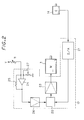
- Fig. 2 is a block diagram of the control system of the winding device.
- Fig. 3 is similar to Fig. 1, but shows a second embodiment of the present invention.
- the winding device comprises a spool 1 on which wire 2 is pre-wound and which acts as a wire source.
- the spool 1 is connected to a feeding motor 3 and the feeding motor 3 rotates the spool 1 to feed the wire 2.
- the wire 2 passes through a feed mechanism 4 and is lead onto a bobbin 7 which is provided on the tip of a spindle 6.
- the spindle 6 is rotated by a drive mechanism 16.
- the bobbin 7 rotates, the wire 2 is wound onto the bobbin 7.
- the feed mechanism 4 is provided with a tension arm 10 on the downstream of the felt pulley 8 used to dust the wire 2.
- a base 10A of the tension arm 10 is supported in free rotation by a plate 9 and can rotate along the plate 9.
- the rotational angle of the tension arm 10 is detected by a potentiometer 11 provided on the base 10A.
- a pulley 12 is provided on the tip of the tension arm 10 which guides the wire 2.
- the wire 2 which is lead from the spool 1 to the felt pulley 8 passes through the pulley 12 and a pulley 13 which is nearer to the bobbin 7 than the pulley 12 and is lead to the bobbin 7.
- a ring shaped member which leads the wire 2 may be provided.
- the pulley 13 is fixed onto the rotational axis of an encoder 14 provided on the plate 9.
- the speed of the wire 2 which is lead to the bobbin 7 via the pulley 13 is detected by the encoder 14.
- a spring 15 is provided between the tension arm 10 and a boss 8A provided on the plate 9.
- the spring 15 effects a force in a clockwise direction on the tension arm 10 and thus a tension corresponding to the elastic force of the spring 15 is exerted on the wire 2.
- the tension arm 10 rotates in a counter clockwise direction, it is possible to calculate the variation in the tension on the wire 2 from the variation of the rotational angle of the tension arm 10.
- the tension arm 10 is constructed from a sufficiently rigid material which is hard to bend so that the variation in tension is accurately reflected in the rotational angle of the tension arm 10.
- a light material is used so that the responsiveness to the variation in tension is high.
- the tension arm becomes thick towards the base 10A and becomes thin towards the tip.
- a controller 17 rotates the spindle 6 at a predetermined rotational speed. Furthermore the controller 17 controls the feeding speed of the wire 2, that is to say, the rotational speed of the feeding motor 3 based on the winding speed of the wire 2 on the bobbin 7 detected by the encoder 14, the tension detected by the potentiometer 11 and the radius of the pulley 1 which is obtained by calculation or by a sensor.
- Fig. 2 is a block diagram which shows the control system of the winding device.
- the controller 17 comprises a D/A converter 21, a CPU (Central Processing Unit) 22, amplifiers 23, 26, an operational amplifier 24, a resistor 25 and a volume 27.
- Pulses output from the encoder 14 are input into the CPU 22 after being converted into analogue signals by the D/A converter 21.
- the potentiometer 11 is a variable resistor which varies the resistance value depending on the rotational angle of the tension arm 10 and which forms a non-inverse amplification circuit together with the operational amplifier 24 and the resistor 25.
- the output of the non-inverse amplification circuit varies depending on the value of the resistance of the potentiometer 11, is amplified by the amplifier 26 and output to the CPU 22.
- the CPU 22 corrects the signal from the encoder 14 based on the variation in tension and the radius of the pulley 1 and outputs the modified signal to the amplifier 23.
- the volume 27 is a variable resistor which regulates the output voltage of the non-inverse amplification circuit.
- the arrangement of the control system is not limited to the circuit shown in Fig. 2.
- the variation in tension or the winding speed of the wire 2 could be detected using a device other than the encoder 14 or the potentiometer 11. It is possible to use an AC motor, a DC motor, a step motor or the like as the feeding motor 3.
- the detected signal from the encoder 14 need not be converted into an analogue signal by the D/A converter 21 but may be directly processed digitally and the feed back control can be performed by hardware or software.
- the winding device of the present invention performs winding as set out below.
- the wire 2 fed from the spool 1 is lead to the bobbin 7 through the feed mechanism 4 and is wound onto the bobbin 7 which rotates at a predetermined rotational speed.
- the feeding motor 3 feeds a necessary length of wire 2 by rotating the spool 1.
- the rotational speed of the feeding motor 3 is controlled based on the wire winding speed of the bobbin 7 detected by the encoder 14 and the radius of the spool 1 obtained by a sensor or by calculation.
- the radius of the bobbin 7 varies according to the rotational angle.
- the controller 17 which receives the detection signal from the encoder 14, rotates the feeding motor 3 in the inverse direction and returns the wire 2 in the direction of the spool 1.
- the rotational displacement of the tension arm 10 due to the variation in the tension is fed back to the feeding motor 3 and the rotational speed of the feeding motor 3 is regulated. In this way, momentary minute variations in the tension of the wire 2 can be automatically absorbed. Since the tension arm 10 is controlled to maintain a constant angle, normally a constant tension is exerted on the wire 2.
- Fig. 3 shows another embodiment of the present invention.
- This embodiment differs from the previous embodiment in that a feed relay mechanism 43 comprising a pulley 41 and a feeding motor 42 is provided on the downstream of a spool 40 which acts as the wire source.
- the provision of the feed relay mechanism 43 allows the wire 2 which is wound beforehand on the spool 40 to be provided to the tension arm 10 after being temporarily wound on the pulley 41 which is driven rotationally by the feeding motor 42.
- the length of wire 2 fed from the pulley 41 is determined depending on the number of rotations of the pulley 41.
- the feeding speed of the wire 2 is decided only by the rotational speed of the feeding motor 42.
Landscapes
- Tension Adjustment In Filamentary Materials (AREA)
- Coil Winding Methods And Apparatuses (AREA)
- Manufacture Of Motors, Generators (AREA)
Applications Claiming Priority (4)
| Application Number | Priority Date | Filing Date | Title |
|---|---|---|---|
| JP33566597 | 1997-12-05 | ||
| JP33566597 | 1997-12-05 | ||
| JP2751898 | 1998-02-09 | ||
| JP10027518A JPH11222357A (ja) | 1997-12-05 | 1998-02-09 | 巻線装置および巻線方法 |
Publications (2)
| Publication Number | Publication Date |
|---|---|
| EP0926090A2 true EP0926090A2 (de) | 1999-06-30 |
| EP0926090A3 EP0926090A3 (de) | 2000-10-18 |
Family
ID=26365442
Family Applications (1)
| Application Number | Title | Priority Date | Filing Date |
|---|---|---|---|
| EP98309668A Withdrawn EP0926090A3 (de) | 1997-12-05 | 1998-11-25 | Wickelvorrichtung und Wickelverfahren |
Country Status (2)
| Country | Link |
|---|---|
| EP (1) | EP0926090A3 (de) |
| JP (1) | JPH11222357A (de) |
Cited By (20)
| Publication number | Priority date | Publication date | Assignee | Title |
|---|---|---|---|---|
| WO2001040557A1 (es) * | 1999-12-03 | 2001-06-07 | Jordi Galan I Llongueras | Unidad independiente de torsionado |
| CN101454850B (zh) * | 2006-05-26 | 2011-08-31 | 日特机械工程株式会社 | 绕线装置、张紧装置以及绕线方法 |
| EP2306473A4 (de) * | 2008-06-27 | 2011-12-28 | Honda Motor Co Ltd | Drahtwickeleinrichtung |
| EP2485227A1 (de) * | 2011-02-02 | 2012-08-08 | Siemens Aktiengesellschaft | Verfahren zur Steuerung eines Prozesses zum Wickeln eines azentrischen Spulenkörpers und nach dem Verfahren arbeitende Vorrichtung |
| ITFI20110087A1 (it) * | 2011-04-28 | 2012-10-29 | Marco Nuti | Procedimento per realizzare avvolgimenti di materiale conduttore su un nucleo polare |
| WO2013105902A1 (en) * | 2012-01-09 | 2013-07-18 | Venture Corporation Limited | An apparatus and method for maintaining consistent tension of a roll of media undergoing un-winding or re-winding |
| CN103434893A (zh) * | 2013-08-30 | 2013-12-11 | 洛阳市明伟机械科技有限公司 | 一种用于捆状绕制机的功能滑轮组 |
| WO2014039005A1 (en) * | 2012-09-04 | 2014-03-13 | Venture Corporation Limited | An apparatus and method for maintaining consistent tension of a flexible flat cable undergoing extension or retraction |
| ITMI20122185A1 (it) * | 2012-12-20 | 2014-06-21 | Btsr Int Spa | Metodo e dispositivo per alimentare a tensione ed a quantita' costante un filo metallico ad una macchina operatrice |
| ITMI20131761A1 (it) * | 2013-10-22 | 2015-04-23 | Marsilli & Co | Dispositivo per la regolazione automatica del tensionamento del filo durante le varie fasi di avvolgimento in macchine per l'avvolgimento di bobine elettriche. |
| CN104190730B (zh) * | 2014-08-11 | 2016-01-13 | 湖北三江航天江北机械工程有限公司 | 水箱拉丝机的排线补偿控制方法 |
| CN105438892A (zh) * | 2014-09-30 | 2016-03-30 | 金华市恒飞电工材料有限公司 | 一种应用于微细线伸线机的收线装置的张力控制系统 |
| CN106960724A (zh) * | 2017-03-31 | 2017-07-18 | 深圳市红昌机电设备有限公司 | 立式绕线机的脚控制方法及系统 |
| EP3333106A1 (de) * | 2016-12-12 | 2018-06-13 | Siemens Aktiengesellschaft | Verfahren zum wickeln eines wickelgutes, steuereinrichtung, computerprogrammprodukt und wickelmaschine |
| IT201600127236A1 (it) * | 2016-12-16 | 2018-06-16 | Marsilli S P A | Dispositivo per la regolazione automatica del tensionamento del filo durante le varie fasi di avvolgimento in macchine per l'avvolgimento di bobine elettriche. |
| CN112299137A (zh) * | 2019-07-30 | 2021-02-02 | 日本电产增成机器装置(浙江)有限公司 | 张力调整单元和自动绕线设备 |
| CN112423531A (zh) * | 2020-11-06 | 2021-02-26 | 苏州利相源信息技术科技有限公司 | 一种用于模具设备的可除尘通讯装置 |
| CN112478941A (zh) * | 2020-12-09 | 2021-03-12 | 苏州创易技研股份有限公司 | 一种电子张力器 |
| CN112908690A (zh) * | 2021-01-15 | 2021-06-04 | 重庆仟知佳科技有限公司 | 一种多功能电感生产绕线机 |
| CN113086768A (zh) * | 2021-05-07 | 2021-07-09 | 武汉合众恒长科技发展有限公司 | 一种主动和被动放绳线管速度控制机构 |
Families Citing this family (9)
| Publication number | Priority date | Publication date | Assignee | Title |
|---|---|---|---|---|
| JP4646274B2 (ja) * | 2000-02-25 | 2011-03-09 | 日特エンジニアリング株式会社 | 巻線組立システム及び巻線機 |
| KR100425669B1 (ko) * | 2001-07-25 | 2004-04-03 | (주)누리 이엔지 | 코어리스 코일 권선용 보빈유닛, 권선기용 스핀들유닛,복수 스핀들 구동형 권선기, 권선기용 텐션장치, 및 코일권선 시스템 |
| CN1295846C (zh) * | 2003-03-12 | 2007-01-17 | 铜陵精达特种电磁线股份有限公司 | 漆包线高速绕线试验仪 |
| JP5385013B2 (ja) * | 2009-06-03 | 2014-01-08 | 株式会社ミツバ | テンション装置 |
| JP5426323B2 (ja) * | 2009-11-05 | 2014-02-26 | 株式会社ミツバ | テンション装置 |
| JP6133831B2 (ja) * | 2014-11-04 | 2017-05-24 | 株式会社キム工 | 糸巻き取り装置 |
| JP7222829B2 (ja) * | 2019-06-24 | 2023-02-15 | 株式会社デンソー | 巻線装置 |
| CN113666197B (zh) * | 2021-10-21 | 2022-02-08 | 江苏安澜万锦电子股份有限公司 | 一种包带机主轴结构及其定时中断控制方法 |
| JP2024032485A (ja) * | 2022-08-29 | 2024-03-12 | 株式会社デンソー | 巻線用テンション制御装置 |
Family Cites Families (4)
| Publication number | Priority date | Publication date | Assignee | Title |
|---|---|---|---|---|
| FR2571034A1 (fr) * | 1984-09-28 | 1986-04-04 | Pourtier Pere Fils Ets | Appareil regulateur de tension pour derouler un fil ou fibre fragile d'une bobine, ou enrouler un tel fil sur une bobine |
| JP2660073B2 (ja) * | 1989-11-15 | 1997-10-08 | 株式会社東芝 | 回転電機の巻線装置 |
| FR2655888A1 (fr) * | 1989-12-20 | 1991-06-21 | Prosys | Devidoir a regulation de tension du fil pour alimenter une bobineuse a partir d'une nourrice. |
| US5080296A (en) * | 1990-09-24 | 1992-01-14 | General Atomics | Low tension wire transfer system |
-
1998
- 1998-02-09 JP JP10027518A patent/JPH11222357A/ja active Pending
- 1998-11-25 EP EP98309668A patent/EP0926090A3/de not_active Withdrawn
Cited By (40)
| Publication number | Priority date | Publication date | Assignee | Title |
|---|---|---|---|---|
| WO2001040557A1 (es) * | 1999-12-03 | 2001-06-07 | Jordi Galan I Llongueras | Unidad independiente de torsionado |
| US6751938B1 (en) * | 1999-12-03 | 2004-06-22 | Jordi Galan I Llongueras | Independent torsioning unit |
| CN101454850B (zh) * | 2006-05-26 | 2011-08-31 | 日特机械工程株式会社 | 绕线装置、张紧装置以及绕线方法 |
| EP2306473A4 (de) * | 2008-06-27 | 2011-12-28 | Honda Motor Co Ltd | Drahtwickeleinrichtung |
| CN102067255B (zh) * | 2008-06-27 | 2013-01-02 | 本田技研工业株式会社 | 卷线装置 |
| US8844858B2 (en) | 2008-06-27 | 2014-09-30 | Honda Motor Co., Ltd. | Wire winding device |
| EP2485227A1 (de) * | 2011-02-02 | 2012-08-08 | Siemens Aktiengesellschaft | Verfahren zur Steuerung eines Prozesses zum Wickeln eines azentrischen Spulenkörpers und nach dem Verfahren arbeitende Vorrichtung |
| CN102629515A (zh) * | 2011-02-02 | 2012-08-08 | 西门子公司 | 控制偏心线圈体缠绕过程的方法和按照该方法工作的装置 |
| CN102629515B (zh) * | 2011-02-02 | 2015-03-25 | 西门子公司 | 控制偏心线圈体缠绕过程的方法和按照该方法工作的装置 |
| US8955789B2 (en) | 2011-02-02 | 2015-02-17 | Siemens Aktiengesellschaft | Method for controlling a process for winding an acentric coil former and device operating according to the method |
| ITFI20110087A1 (it) * | 2011-04-28 | 2012-10-29 | Marco Nuti | Procedimento per realizzare avvolgimenti di materiale conduttore su un nucleo polare |
| WO2013105902A1 (en) * | 2012-01-09 | 2013-07-18 | Venture Corporation Limited | An apparatus and method for maintaining consistent tension of a roll of media undergoing un-winding or re-winding |
| WO2014039005A1 (en) * | 2012-09-04 | 2014-03-13 | Venture Corporation Limited | An apparatus and method for maintaining consistent tension of a flexible flat cable undergoing extension or retraction |
| WO2014097027A1 (en) | 2012-12-20 | 2014-06-26 | Btsr International S.P.A. | Method and device for feeding a metal wire to an operating machine at a constant tension and quantity |
| RU2636326C2 (ru) * | 2012-12-20 | 2017-11-22 | Бтср Интернэшнл С.П.А. | Способ и устройство для подачи металлической проволоки к операционной машине с постоянными натяжением и количеством |
| ITMI20122185A1 (it) * | 2012-12-20 | 2014-06-21 | Btsr Int Spa | Metodo e dispositivo per alimentare a tensione ed a quantita' costante un filo metallico ad una macchina operatrice |
| CN104870351A (zh) * | 2012-12-20 | 2015-08-26 | Btsr国际股份公司 | 用于以恒定的张力和量将金属线材进给至操作机器的方法及装置 |
| US9663321B2 (en) | 2012-12-20 | 2017-05-30 | Btsr International S.P.A. | Method and device for feeding a metal wire to an operating machine at a constant tension and quantity |
| CN104870351B (zh) * | 2012-12-20 | 2017-06-13 | Btsr国际股份公司 | 用于以恒定的张力和量将金属线材进给至操作机器的方法及装置 |
| KR101834053B1 (ko) | 2012-12-20 | 2018-03-02 | 비티에스알 인터내셔널 에스.피.에이. | 금속 와이어를 일정한 장력 및 양으로 작업 기계에 급송하기 위한 방법 및 장치 |
| CN103434893A (zh) * | 2013-08-30 | 2013-12-11 | 洛阳市明伟机械科技有限公司 | 一种用于捆状绕制机的功能滑轮组 |
| CN103434893B (zh) * | 2013-08-30 | 2016-04-13 | 王晓晓 | 一种用于捆状绕制机的功能滑轮组 |
| ITMI20131761A1 (it) * | 2013-10-22 | 2015-04-23 | Marsilli & Co | Dispositivo per la regolazione automatica del tensionamento del filo durante le varie fasi di avvolgimento in macchine per l'avvolgimento di bobine elettriche. |
| EP2866236A1 (de) * | 2013-10-22 | 2015-04-29 | Marsilli & Co. S.P.A. | Vorrichtung für automatische Drahtspannungsanpassungen während verschiedener Stufen von Wickelmaschinen zum Wickeln von elektrischen Spulen |
| CN104190730B (zh) * | 2014-08-11 | 2016-01-13 | 湖北三江航天江北机械工程有限公司 | 水箱拉丝机的排线补偿控制方法 |
| CN105438892A (zh) * | 2014-09-30 | 2016-03-30 | 金华市恒飞电工材料有限公司 | 一种应用于微细线伸线机的收线装置的张力控制系统 |
| CN105438892B (zh) * | 2014-09-30 | 2019-01-29 | 浙江恒飞控股有限公司 | 一种应用于微细线伸线机的收线装置的张力控制系统 |
| EP3333106A1 (de) * | 2016-12-12 | 2018-06-13 | Siemens Aktiengesellschaft | Verfahren zum wickeln eines wickelgutes, steuereinrichtung, computerprogrammprodukt und wickelmaschine |
| US10858215B2 (en) | 2016-12-12 | 2020-12-08 | Siemens Aktiengesellschaft | Method for coiling a coiled product, control installation, computer software product, and coiling machine |
| CN108217269B (zh) * | 2016-12-12 | 2020-08-14 | 西门子公司 | 用于卷绕卷材的方法、控制装置、存储介质和卷绕机 |
| CN108217269A (zh) * | 2016-12-12 | 2018-06-29 | 西门子公司 | 用于卷绕卷材的方法、控制装置、存储介质和卷绕机 |
| EP3336864A1 (de) * | 2016-12-16 | 2018-06-20 | Marsilli S.p.A. | Vorrichtung für automatische drahtspannungsanpassungen während verschiedener stufen von wickelmaschinen zum wickeln von elektrischen spulen |
| IT201600127236A1 (it) * | 2016-12-16 | 2018-06-16 | Marsilli S P A | Dispositivo per la regolazione automatica del tensionamento del filo durante le varie fasi di avvolgimento in macchine per l'avvolgimento di bobine elettriche. |
| CN106960724A (zh) * | 2017-03-31 | 2017-07-18 | 深圳市红昌机电设备有限公司 | 立式绕线机的脚控制方法及系统 |
| CN112299137A (zh) * | 2019-07-30 | 2021-02-02 | 日本电产增成机器装置(浙江)有限公司 | 张力调整单元和自动绕线设备 |
| CN112423531A (zh) * | 2020-11-06 | 2021-02-26 | 苏州利相源信息技术科技有限公司 | 一种用于模具设备的可除尘通讯装置 |
| CN112478941A (zh) * | 2020-12-09 | 2021-03-12 | 苏州创易技研股份有限公司 | 一种电子张力器 |
| CN112478941B (zh) * | 2020-12-09 | 2022-07-08 | 苏州创易技研股份有限公司 | 一种电子张力器 |
| CN112908690A (zh) * | 2021-01-15 | 2021-06-04 | 重庆仟知佳科技有限公司 | 一种多功能电感生产绕线机 |
| CN113086768A (zh) * | 2021-05-07 | 2021-07-09 | 武汉合众恒长科技发展有限公司 | 一种主动和被动放绳线管速度控制机构 |
Also Published As
| Publication number | Publication date |
|---|---|
| JPH11222357A (ja) | 1999-08-17 |
| EP0926090A3 (de) | 2000-10-18 |
Similar Documents
| Publication | Publication Date | Title |
|---|---|---|
| EP0926090A2 (de) | Wickelvorrichtung und Wickelverfahren | |
| US5421534A (en) | Apparatus for and method of controlling tension of a filamentary material | |
| AU2008202605B2 (en) | A method of controlling tension in a moving web material | |
| US4977466A (en) | Magnetic tape wind-up control method, and tape wind-up apparatus | |
| EP0553898A2 (de) | Drahtspanner | |
| JPH01133871A (ja) | 巻糸の形成時に糸群の巻取張力を制御する方法 | |
| EP0703658B1 (de) | Verfahren und Vorrichtung zum Ausbalanzieren von Rotorwicklungen während des Wicklungsvorganges | |
| EP0618661B1 (de) | Verfahren und Vorrichtungen zum Wickeln eines Ankers mit verbesserter Auswuchtung | |
| JPH0712883B2 (ja) | 長尺材巻取機の張力制御装置 | |
| JPH05228738A (ja) | 放電加工機のリボン又はワイヤ電極の張力測定及び/又は張力制御装置 | |
| JP2001328766A (ja) | 張力制御装置 | |
| JP3522868B2 (ja) | 巻取り・巻戻し制御装置 | |
| CN100413769C (zh) | 卷取装置的速度控制方法及速度控制装置 | |
| KR940004505B1 (ko) | Vcr의 테이프 텐션 제어장치 | |
| JPH09226996A (ja) | 張力制御機構を備えた巻取装置 | |
| US5715111A (en) | Tape tension control circuit that opens take-up reel tension feedback loop during capstan-free operation | |
| JPH05278943A (ja) | 巻線のテンション制御装置 | |
| JP3921103B2 (ja) | 抄紙巻き取り張力制御装置 | |
| JPH02182658A (ja) | 用紙巻取方式 | |
| JPH04251061A (ja) | 巻取装置 | |
| GB2354088A (en) | Controlling film tension in film scanner | |
| JP2024101539A (ja) | 巻線装置及び巻線方法 | |
| JPS60133561A (ja) | テ−プ張力制御方式 | |
| JPH082822A (ja) | 線条体の一定速度送出・巻取ボビン装置 | |
| JPH07121237A (ja) | 摩擦駆動装置 |
Legal Events
| Date | Code | Title | Description |
|---|---|---|---|
| PUAI | Public reference made under article 153(3) epc to a published international application that has entered the european phase |
Free format text: ORIGINAL CODE: 0009012 |
|
| 17P | Request for examination filed |
Effective date: 19981201 |
|
| AK | Designated contracting states |
Kind code of ref document: A2 Designated state(s): CH DE FR GB IT LI |
|
| AX | Request for extension of the european patent |
Free format text: AL;LT;LV;MK;RO;SI |
|
| PUAL | Search report despatched |
Free format text: ORIGINAL CODE: 0009013 |
|
| AK | Designated contracting states |
Kind code of ref document: A3 Designated state(s): AT BE CH CY DE DK ES FI FR GB GR IE IT LI LU MC NL PT SE |
|
| AX | Request for extension of the european patent |
Free format text: AL;LT;LV;MK;RO;SI |
|
| AKX | Designation fees paid |
Free format text: CH DE FR GB IT LI |
|
| 17Q | First examination report despatched |
Effective date: 20020731 |
|
| STAA | Information on the status of an ep patent application or granted ep patent |
Free format text: STATUS: THE APPLICATION IS DEEMED TO BE WITHDRAWN |
|
| 18D | Application deemed to be withdrawn |
Effective date: 20021211 |