EP0926255B1 - Procédé de dépôt par pulvérisation thermique pour les extrémités des aubes de turbine - Google Patents
Procédé de dépôt par pulvérisation thermique pour les extrémités des aubes de turbine Download PDFInfo
- Publication number
- EP0926255B1 EP0926255B1 EP98310528A EP98310528A EP0926255B1 EP 0926255 B1 EP0926255 B1 EP 0926255B1 EP 98310528 A EP98310528 A EP 98310528A EP 98310528 A EP98310528 A EP 98310528A EP 0926255 B1 EP0926255 B1 EP 0926255B1
- Authority
- EP
- European Patent Office
- Prior art keywords
- spray
- blades
- softened
- coating
- particles
- Prior art date
- Legal status (The legal status is an assumption and is not a legal conclusion. Google has not performed a legal analysis and makes no representation as to the accuracy of the status listed.)
- Expired - Lifetime
Links
- 238000000034 method Methods 0.000 title claims description 69
- 238000005507 spraying Methods 0.000 title claims description 19
- 238000000576 coating method Methods 0.000 claims description 144
- 239000011248 coating agent Substances 0.000 claims description 132
- 239000007921 spray Substances 0.000 claims description 114
- 239000007789 gas Substances 0.000 claims description 92
- 239000002245 particle Substances 0.000 claims description 47
- 239000000843 powder Substances 0.000 claims description 44
- 238000010438 heat treatment Methods 0.000 claims description 20
- 238000001816 cooling Methods 0.000 claims description 14
- 238000000151 deposition Methods 0.000 claims description 13
- 239000000463 material Substances 0.000 claims description 13
- RUDFQVOCFDJEEF-UHFFFAOYSA-N yttrium(III) oxide Inorganic materials [O-2].[O-2].[O-2].[Y+3].[Y+3] RUDFQVOCFDJEEF-UHFFFAOYSA-N 0.000 claims description 12
- MCMNRKCIXSYSNV-UHFFFAOYSA-N Zirconium dioxide Chemical compound O=[Zr]=O MCMNRKCIXSYSNV-UHFFFAOYSA-N 0.000 claims description 10
- 239000012159 carrier gas Substances 0.000 claims description 10
- 238000002347 injection Methods 0.000 claims description 7
- 239000007924 injection Substances 0.000 claims description 7
- 238000005260 corrosion Methods 0.000 claims description 2
- 230000007797 corrosion Effects 0.000 claims description 2
- 238000007789 sealing Methods 0.000 claims 1
- 239000000758 substrate Substances 0.000 description 35
- XKRFYHLGVUSROY-UHFFFAOYSA-N Argon Chemical compound [Ar] XKRFYHLGVUSROY-UHFFFAOYSA-N 0.000 description 20
- 239000011247 coating layer Substances 0.000 description 17
- 239000000203 mixture Substances 0.000 description 15
- 239000010410 layer Substances 0.000 description 11
- 229910052786 argon Inorganic materials 0.000 description 10
- UFHFLCQGNIYNRP-UHFFFAOYSA-N Hydrogen Chemical compound [H][H] UFHFLCQGNIYNRP-UHFFFAOYSA-N 0.000 description 8
- PXHVJJICTQNCMI-UHFFFAOYSA-N Nickel Chemical compound [Ni] PXHVJJICTQNCMI-UHFFFAOYSA-N 0.000 description 8
- 230000008021 deposition Effects 0.000 description 7
- 239000001257 hydrogen Substances 0.000 description 6
- 229910052739 hydrogen Inorganic materials 0.000 description 6
- 229910052759 nickel Inorganic materials 0.000 description 4
- 230000001464 adherent effect Effects 0.000 description 3
- 229910052782 aluminium Inorganic materials 0.000 description 3
- XAGFODPZIPBFFR-UHFFFAOYSA-N aluminium Chemical compound [Al] XAGFODPZIPBFFR-UHFFFAOYSA-N 0.000 description 3
- 238000004140 cleaning Methods 0.000 description 3
- 230000007423 decrease Effects 0.000 description 3
- 230000008018 melting Effects 0.000 description 3
- 238000002844 melting Methods 0.000 description 3
- RTAQQCXQSZGOHL-UHFFFAOYSA-N Titanium Chemical compound [Ti] RTAQQCXQSZGOHL-UHFFFAOYSA-N 0.000 description 2
- 229910052770 Uranium Inorganic materials 0.000 description 2
- 239000011159 matrix material Substances 0.000 description 2
- 229910052751 metal Inorganic materials 0.000 description 2
- 239000002184 metal Substances 0.000 description 2
- 230000003647 oxidation Effects 0.000 description 2
- 238000007254 oxidation reaction Methods 0.000 description 2
- 238000007750 plasma spraying Methods 0.000 description 2
- 230000035945 sensitivity Effects 0.000 description 2
- 239000010936 titanium Substances 0.000 description 2
- 229910052719 titanium Inorganic materials 0.000 description 2
- 229910000838 Al alloy Inorganic materials 0.000 description 1
- NPXOKRUENSOPAO-UHFFFAOYSA-N Raney nickel Chemical compound [Al].[Ni] NPXOKRUENSOPAO-UHFFFAOYSA-N 0.000 description 1
- 238000005299 abrasion Methods 0.000 description 1
- 239000010953 base metal Substances 0.000 description 1
- 230000015572 biosynthetic process Effects 0.000 description 1
- 239000000919 ceramic Substances 0.000 description 1
- 229910010293 ceramic material Inorganic materials 0.000 description 1
- 239000008199 coating composition Substances 0.000 description 1
- 238000002485 combustion reaction Methods 0.000 description 1
- 230000003247 decreasing effect Effects 0.000 description 1
- 230000000694 effects Effects 0.000 description 1
- 238000010891 electric arc Methods 0.000 description 1
- 238000009713 electroplating Methods 0.000 description 1
- 238000005516 engineering process Methods 0.000 description 1
- 230000007613 environmental effect Effects 0.000 description 1
- 239000000446 fuel Substances 0.000 description 1
- 239000001307 helium Substances 0.000 description 1
- 229910052734 helium Inorganic materials 0.000 description 1
- SWQJXJOGLNCZEY-UHFFFAOYSA-N helium atom Chemical compound [He] SWQJXJOGLNCZEY-UHFFFAOYSA-N 0.000 description 1
- 230000003116 impacting effect Effects 0.000 description 1
- 230000003993 interaction Effects 0.000 description 1
- 239000007788 liquid Substances 0.000 description 1
- 238000004519 manufacturing process Methods 0.000 description 1
- 230000000873 masking effect Effects 0.000 description 1
- 230000013011 mating Effects 0.000 description 1
- RVTZCBVAJQQJTK-UHFFFAOYSA-N oxygen(2-);zirconium(4+) Chemical compound [O-2].[O-2].[Zr+4] RVTZCBVAJQQJTK-UHFFFAOYSA-N 0.000 description 1
- 238000004663 powder metallurgy Methods 0.000 description 1
- 238000010248 power generation Methods 0.000 description 1
- 238000002360 preparation method Methods 0.000 description 1
- 239000011253 protective coating Substances 0.000 description 1
- 230000005855 radiation Effects 0.000 description 1
- 150000003839 salts Chemical class 0.000 description 1
- 230000011218 segmentation Effects 0.000 description 1
- 238000005245 sintering Methods 0.000 description 1
- 238000007711 solidification Methods 0.000 description 1
- 230000008023 solidification Effects 0.000 description 1
- 238000004901 spalling Methods 0.000 description 1
- 229910000601 superalloy Inorganic materials 0.000 description 1
- 150000003568 thioethers Chemical class 0.000 description 1
- 229910001928 zirconium oxide Inorganic materials 0.000 description 1
Images

Classifications
-
- C—CHEMISTRY; METALLURGY
- C23—COATING METALLIC MATERIAL; COATING MATERIAL WITH METALLIC MATERIAL; CHEMICAL SURFACE TREATMENT; DIFFUSION TREATMENT OF METALLIC MATERIAL; COATING BY VACUUM EVAPORATION, BY SPUTTERING, BY ION IMPLANTATION OR BY CHEMICAL VAPOUR DEPOSITION, IN GENERAL; INHIBITING CORROSION OF METALLIC MATERIAL OR INCRUSTATION IN GENERAL
- C23C—COATING METALLIC MATERIAL; COATING MATERIAL WITH METALLIC MATERIAL; SURFACE TREATMENT OF METALLIC MATERIAL BY DIFFUSION INTO THE SURFACE, BY CHEMICAL CONVERSION OR SUBSTITUTION; COATING BY VACUUM EVAPORATION, BY SPUTTERING, BY ION IMPLANTATION OR BY CHEMICAL VAPOUR DEPOSITION, IN GENERAL
- C23C4/00—Coating by spraying the coating material in the molten state, e.g. by flame, plasma or electric discharge
- C23C4/02—Pretreatment of the material to be coated, e.g. for coating on selected surface areas
-
- B—PERFORMING OPERATIONS; TRANSPORTING
- B05—SPRAYING OR ATOMISING IN GENERAL; APPLYING FLUENT MATERIALS TO SURFACES, IN GENERAL
- B05D—PROCESSES FOR APPLYING FLUENT MATERIALS TO SURFACES, IN GENERAL
- B05D1/00—Processes for applying liquids or other fluent materials
- B05D1/02—Processes for applying liquids or other fluent materials performed by spraying
- B05D1/12—Applying particulate materials
-
- B—PERFORMING OPERATIONS; TRANSPORTING
- B05—SPRAYING OR ATOMISING IN GENERAL; APPLYING FLUENT MATERIALS TO SURFACES, IN GENERAL
- B05B—SPRAYING APPARATUS; ATOMISING APPARATUS; NOZZLES
- B05B16/00—Spray booths
-
- C—CHEMISTRY; METALLURGY
- C23—COATING METALLIC MATERIAL; COATING MATERIAL WITH METALLIC MATERIAL; CHEMICAL SURFACE TREATMENT; DIFFUSION TREATMENT OF METALLIC MATERIAL; COATING BY VACUUM EVAPORATION, BY SPUTTERING, BY ION IMPLANTATION OR BY CHEMICAL VAPOUR DEPOSITION, IN GENERAL; INHIBITING CORROSION OF METALLIC MATERIAL OR INCRUSTATION IN GENERAL
- C23C—COATING METALLIC MATERIAL; COATING MATERIAL WITH METALLIC MATERIAL; SURFACE TREATMENT OF METALLIC MATERIAL BY DIFFUSION INTO THE SURFACE, BY CHEMICAL CONVERSION OR SUBSTITUTION; COATING BY VACUUM EVAPORATION, BY SPUTTERING, BY ION IMPLANTATION OR BY CHEMICAL VAPOUR DEPOSITION, IN GENERAL
- C23C4/00—Coating by spraying the coating material in the molten state, e.g. by flame, plasma or electric discharge
- C23C4/12—Coating by spraying the coating material in the molten state, e.g. by flame, plasma or electric discharge characterised by the method of spraying
-
- F—MECHANICAL ENGINEERING; LIGHTING; HEATING; WEAPONS; BLASTING
- F01—MACHINES OR ENGINES IN GENERAL; ENGINE PLANTS IN GENERAL; STEAM ENGINES
- F01D—NON-POSITIVE DISPLACEMENT MACHINES OR ENGINES, e.g. STEAM TURBINES
- F01D5/00—Blades; Blade-carrying members; Heating, heat-insulating, cooling or antivibration means on the blades or the members
- F01D5/12—Blades
- F01D5/28—Selecting particular materials; Particular measures relating thereto; Measures against erosion or corrosion
- F01D5/288—Protective coatings for blades
-
- Y—GENERAL TAGGING OF NEW TECHNOLOGICAL DEVELOPMENTS; GENERAL TAGGING OF CROSS-SECTIONAL TECHNOLOGIES SPANNING OVER SEVERAL SECTIONS OF THE IPC; TECHNICAL SUBJECTS COVERED BY FORMER USPC CROSS-REFERENCE ART COLLECTIONS [XRACs] AND DIGESTS
- Y02—TECHNOLOGIES OR APPLICATIONS FOR MITIGATION OR ADAPTATION AGAINST CLIMATE CHANGE
- Y02T—CLIMATE CHANGE MITIGATION TECHNOLOGIES RELATED TO TRANSPORTATION
- Y02T50/00—Aeronautics or air transport
- Y02T50/60—Efficient propulsion technologies, e.g. for aircraft
Definitions
- This invention relates to a process for controllably applying thermal spray coating onto substrates and more particularly, to applying a plurality of coating layers onto gas turbine engine rotor blade tips.
- Large gas turbine engines are widely used for aircraft propulsion and for ground based power generation.
- Such large gas turbine engines are of the axial type, and include a compressor section, a combustor section, and a turbine section, with the compressor section normally preceded by a fan section.
- An annular flow path for working medium gases extends axially through the sections of the engine.
- Each of the fan, compressor, and turbine sections comprises a plurality of disks mounted on a shaft, with a plurality of airfoil shaped blades projecting radially therefrom.
- a hollow case surrounds the various engine sections.
- a plurality of stationary vanes are located between the disks and project inwardly from the case assembly which surrounds the disks.
- the fan, compressor, and turbine sections As the working medium gases are flowed axially, they alternately contact moving blades and the stationary vanes.
- air is compressed and the compressed air is combined with fuel and burned in the combustion section to provide high pressure, high temperature gases.
- the working medium gases then flow through the turbine section, where energy is extracted by causing the bladed turbine disks to rotate. A portion of this energy is used to operate the compressor section and the fan section.
- Engine efficiency depends to a significant extent upon minimizing leakage of the gas flow to maximize interaction between the gas stream and the moving and stationary airfoils.
- a major source of inefficiency is leakage of gas around the tips of the compressor blades, between the blade tips and, the engine case. Accordingly, means to improve efficiency by reduction of leakage are increasingly important.
- a close tolerance fit may be obtained by fabricating the blade tips and the engine case to mate to a very close tolerance range, this fabrication process is extremely costly and time consuming.
- the coefficients of expansion of the blade tips and the engine case parts may differ, thus causing the clearance space to either increase or decrease.
- a significant decrease in clearance results in contact between blades and housing, and friction between the parts generates heat causing a significant elevation of temperatures and possible damage to one or both members.
- increased clearance space would permit gas to escape between the compressor blade and housing, thus decreasing efficiency.
- One approach to increase efficiency is to apply an abradable coating of suitable material to the interior surface of the compressor housing, which when abraded allows for the creation of a channel between the blade tips and the housing. Leakage between the blade tips and the housing is limited to airflow in the channel.
- Various coating techniques have been employed to coat the inside diameter of the compressor housing with an abradable coating that can be worn away by the frictional contact of the compressor blade, to provide a close fitting channel in which the blade tip may travel.
- the blade and the case may expand or contract without resulting in significant gas leakage between the blade tip and the housing.
- abrasive layers are sometimes applied to the blade tip surface by a variety of methods. See, for example, U.S. Patent No. 4,802,828, of Rutz et al, which suggests several techniques for providing an abrasive layer on a blade tip, including powder metallurgy techniques, plasma spray techniques, and electroplating techniques; Schaefer et al, U.S. Patent No.
- Plasma spraying devices and techniques are well known in the art for depositing protective coatings on underlying substrates.
- One known device is illustrated in U.S. Patent No. 3,145,287 to Siebein et al entitled "Plasma Flame Generator and Spray Gun"
- a plasma-forming gas forms a sheath around an electric arc.
- the sheath of gases constricts and extends the arc part way down the nozzle.
- the gas is converted to a plasma state and leaves the arc and nozzle as a hot plasma stream. Powders are injected into the hot plasma stream and propelled onto the surface of the substrate to be coated.
- the present invention provides a process for applying thermal coating to the tips of gas turbine engine rotor blades having a tip, an airfoil and a root, the airfoil being disposed between the tip and the root and having a leading edge, a trailing edge, a suction surface and a pressure surface, which extend between the edges, comprising the steps of:
- the process includes the step of translating the apparatus for forming and propelling the spray coating, such as a spray gun, between a first and second position in a direction substantially parallel to the plane of rotation of the fixture which allows for a thin layer of thermal spray coating to be deposited on the tips of the blades each time they pass in front of the spray gun which build up to a plurality of layers, resulting in a splat structure with vertical microcracks.
- the spray coating such as a spray gun
- the process includes the step of heating the tips of the rotor blades and the fixture to an elevated temperature during coating.
- a primary feature of the present invention is the relative motion between the rotating holding fixture for the blades and the apparatus for forming and propelling the coating medium.
- Another primary feature is disposing and rotating the blades in the holding fixture such that points receiving the coating on the blade tips describe a circle about the axis of rotation of the fixture.
- the holding fixture is rotated such that adjacent points on the blade tips approximate a surface of rotation substantially parallel to the surface of rotation which the blade tips will experience in an operating engine.
- Another preferred feature is the step of translating the apparatus for forming and propelling the spray coating between a first and second position. In one embodiment, the spray coating apparatus moves in a direction substantially parallel to the plane of rotation of the fixture.
- Another preferred feature is heating the blades to an optimum temperature by passing the blades in front of the spray coating apparatus and through the plasma gas stream. Another preferred feature is depositing the coating medium by passing the blades through the spray of particles of softened coating medium. Another preferred feature is cooling the blades by moving them away from the spray gun, after an independent source of the deposition of each coating layer. Another preferred feature is cooling the blades by directing an independent source of cooling air on the blade tips as the blades rotate away from the gun. Another preferred feature is heating the blades using an independent source of heat before the blades re-enter the plasma gas stream. Another preferred feature of the present invention is the use of control processing parameters to apply the plurality of coating layers. These parameters include the relative speed of the holding fixture to the apparatus for providing the coating (e.g. spray gun), distance from spray gun-to-blade tips, coating powder feed rate, plasma gas stream flow and the power of the spray gun.
- control processing parameters include the relative speed of the holding fixture to the apparatus for providing the coating (e.g. spray gun), distance from spray gun
- a primary advantage of the present invention is the quality of coating applied to the tips of rotor blades which results from using the process to distribute among a multiplicity of the rotor blades any variations in the process flow parameters affecting the stream of particles propelled against the tips.
- the coating process of the present invention has less sensitivity to process variations than a process which allows variations to occur only on one blade.
- Another advantage is the reproducible and reliable process that results due to the use of the control parameters. This process can be used to repetitively apply the coating on substrate surfaces.
- Another advantage is the ease and speed of application of the coating on the surfaces of a large number of blades at a given time which results from the size of the holding fixture and process which accommodates a number of blades. Using a holding fixture that accommodates a plurality of blades, the resultant fixturing time is minimized.
- Another advantage of one preferred embodiment of the present invention is the application of coating to substrates without the use of additional heating apparatus for the substrates. During coating deposition, the optimum amount of heat required is transmitted to the substrates by the plasma gas and the molten coating powder. The rotor blade is not overheated during the coating process. As a result, a rotor blade can be coated without changing the microstructure or properties of the substrate.
- Fig. 2 shows a schematic representation of an apparatus for forming and propelling particles of coating medium and a holding fixture.
- a plurality of rotating blades such as compressor blades 10 are positioned in the cylindrical holding fixture 12.
- the holding fixture has an axis of rotation Ar.
- the holding fixture can accommodate a large number of blades, up to a full stage of blades.
- the fixture diameter ranges from about eighteen to thirty-six inches (18 to 36") (457 to 914 mm), preferably about twenty to twenty-eight inches (20 to 28") (508 to 711 mm) to approximate the size of the flowpath of the engine.
- the large size of the fixture can accommodate an entire stage of blades.
- Each rotor blade has a root and a platform.
- An airfoil extends from the platform and terminates in a tip.
- Each airfoil has a leading edge and a trailing edge.
- a suction surface and a pressure surface extend between the edges.
- the blades are oriented such that points on the blade tips describe a circle about the axis of rotation of the holding fixture. The blade tips face in the outward direction from the holding fixture.
- the apparatus for propelling particles toward the blade tips is in close proximity to the holding fixture.
- the spray coating apparatus includes a spray gun 16 positioned at the outer diameter of the cylindrical fixture for depositing the layers.
- the spray gun is translatable in different directions with respect to the holding fixture.
- the spray coating apparatus forms a heated plasma including molten particles, such as molten zirconium oxide particles, which are propelled in the heated plasma gas stream toward the blades disposed in the fixture.
- the blades are positioned in the holding fixture such that adjacent points on the blade tips approximate a surface of rotation substantially parallel to the surface of rotation which the blade tip will experience while in a working engine.
- the gun moves up and down in a direction substantially parallel to the plane of rotation of the fixture, coating the blades in sequence.
- the thickness of the abrasive coating deposited depends on the application of the substrate. In compressor and brush seal applications, the abrasive layer may have a thickness ranging from five to forty mils (5 to 40 mils) (0.13 to 1.02 mm).
- FIG. 3 is an enlarged view taken along lines 3-3 of FIG. 2 showing the relationship between the plasma spray propelled from the apparatus for forming and propelling particles and the blade tips disposed in the holding fixture.
- the circumferential width of the spray can range from the size of the circumferential width of the blades to a width ten times (10x) that of the circumferential width of the blades. This enables the spray coating to be deposited uniformly onto the suction and pressure surfaces of the airfoil of the blade.
- the phenomenon of overspraying is known in the art, even in processes that spray coat straight onto blade tips that are stationary. However, the overspray that results from the present invention process coats more airfoil surface area and is applied uniformly as compared with prior art processes.
- the overspray onto the airfoil surfaces provides for better adhesion of the spray coating onto the blades.
- the coating is not subject to chipping at the leading and trailing edges as by overspraying and applying the coating to the leading and trailing edges of the blade and to contiguous areas of the suction and pressure surfaces, as well as to the tip itself, a more durable blade tip may be obtained.
- the processing steps of the invention are controlled to produce vertical microcracking (essentially perpendicular to the bond coat surface) and are specific to variables such as gun-type and fixture geometry.
- the vertical microcracks may extend through a top coating layer to a bond coating layer.
- the vertical microcracks do not extend to the substrate surface.
- the processing steps include the selection of certain parameters. These parameters include rotating the fixture at a preselected speed, angling the gun with respect to the substrate, moving the gun at a preselected traverse speed, heating the substrate to a preselected temperature, injecting the coating powder at a preselected rate, and flowing the carrier gas and plasma gases at preselected flow rates. These parameters all influence the structure of the coating and as such should be adjusted to provide uniform coating of compressor blades, or other substrates.
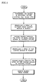
- the process for controllably applying spray coating as flow charted in FIG. 1, includes a number of interrelated steps beginning with providing blades having clean, exposed blade tips and protected airfoil and root surfaces typically provided by masking.
- Conventional cleaning and preparation of the blade tip prior to application of the abrasive layer should be conducted.
- the surface of the blade tip is cleaned and roughened to enhance adherence of subsequently applied coating materials.
- Such cleaning can include mechanical abrasion such as through a vapor or air blast type process employing dry or liquid carried abrasive particles impacting the surface.
- blades Prior to cleaning the surface, blades are suitably masked.
- the process includes propelling a spray of particles of softened bond coating medium toward the blade tips.
- the step of propelling the coating medium includes the step of forming a spray of particles of softened bond coating medium in the spray coating apparatus.
- This step includes flowing bond coat powder and carrier gases into a high-temperature plasma gas stream. In the plasma gas stream, the powder particles are melted and accelerated toward the substrate. Generally, the powder feed rate should be adjusted to provide adequate consistency and amount of bond coating.
- the bond coat powder feed rate ranges from thirty to fifty-five grams per minute (30 to 55 grams/min). Carrier gas flow (argon gas) is used to maintain the powder under pressure and facilitate powder feed.
- the carrier gas flow rate ranges from four to eight standard cubic feet per hour (4 to 8 scfh) (1.9 to 3.8 standard liters per minute (SLM)). Standard conditions are herein defined as about room temperature (77°F)(25°C) and about one atmosphere of pressure (760 mmHg) (101 kPa).
- the gases that make up the plasma gas stream comprise of a primary gas (argon gas) and a secondary gas (hydrogen gas). Helium gas may also be used as a secondary gas.
- the primary gas flow rate in the gun ranges from seventy-five to one hundred and fifteen standard cubic feet per hour (75 to 115 scfh) (35 to 54 SLM), while the secondary gas flow rate ranges from ten to twenty-five standard cubic feet per hour (10 to 25 scfh) (4.7 to 12 SLM).
- Spray gun power generally ranges from thirty to fifty kilowatts (30 to 50 KW).
- the process then includes the step of translating the spray of softened bond coating medium at a distance ranging between about four to six inches (4 to 6") (102 to 152 mm) from the blade tips, between a first and second position.
- the spray gun is moved in a direction substantially parallel to the plane of rotation of the holding fixture.
- Spray gun traverse speed during bond coat deposition ranges from six to twelve inches per minute (6 to 12 in/min) (152 to 305 mm/min).
- the process includes passing the blades through the spray of particles of softened bond coating medium by rotating the fixture about its axis of rotation.
- This step includes heating the blades to a temperature of two hundred to four hundred and fifty degrees Fahrenheit (200 to 450°F) (93 to 232°C) by passing the blades in front of the spray gun and hot plasma gas stream.
- the step of passing the blades through the spray of particles of softened bond coating medium also includes cooling the blades and the coating layer deposited by rotating them away from the spray gun. Additional cooling of the blades can be provided by directing a cooling air stream or cooling jet on the blades or the fixture. Independent sources of heating can also be provided to heat the blades prior to the blades entering the spray of particles of coating medium.
- the independent heating source would allow for control of blade temperature without adjusting the spray gun to provide heating.
- the cylindrical fixture rotates at a speed which ranges from twenty to seventy-five revolutions per minute (20 to 75 rpm), depending on substrate diameter.
- the surface speed of the blades ranges typically from one hundred and twenty-five to three hundred surface feet per minute (125 to 300 sfpm)(0.635 to 1.52 m/s).
- the coating process then includes the step of forming a spray of particles of softened top coating medium.
- This step includes flowing top coat powder and carrier gases into the high-temperature plasma gas stream.
- the powder feed rate should be adjusted to provide adequate mix to cover the substrate, yet not be so great as to reduce melting and crack formation.
- Top coat powder feed rate ranges from fifteen to forty grams per minute (15 to 40 grams/min).
- Carrier gas flow argon gas
- the flow rate ranges from four to eight standard cubic feet per hour (4 to 8 scfh) (1.9 to 3.8 SLM).
- standard conditions are herein defined as about room temperature (77°F) (25°C) and about one atmosphere of pressure (760 mmHg) (101 kPa).
- the step of forming a spray of particles of softened top coating medium includes the injection of the top coat powder angled such that it imparts a component of velocity to the powder which is opposite to the direction of flow of the plasma toward the rotating fixture.
- the projection of the injection angle in a plane perpendicular to the axis of rotation of the holding fixture lies in a range from sixty-five to eighty-five degrees (65 to 85°). This injection angle serves to introduce the top coat powder further back into the plasma plume, thus increasing the residence time of the powder in the plasma gas stream. The increased residence time in the plasma gas stream provides for better melting of the powder particles.
- Primary gas flow (argon gas) in the gun ranges from fifty to ninety standard cubic feet per hour (50 to 90 scfh) (24 to 43 SLM).
- secondary gas flow (hydrogen gas) in the gun ranges from ten to thirty scfh (10 to 30 scfh) (4.7 to 14 SLM).
- Spray gun power generally ranges from thirty to fifty kilowatts (30 to 50 KW).
- the process further includes the step of translating a spray of softened top coating medium at a distance ranging from three to four inches (3 to 4") (76 to 102 mm) from the blade tips, between a first and second position in a direction substantially normal to the plane of rotation of the holding fixture.
- Spray gun traverse speed across each part during deposition ranges from two to ten inches per minute (2 to 10 in/min) (50.8 to 254 mm/min).
- the gun-to-substrate distance may be varied with the intent of maintaining the appropriate temperature level at the substrate surface. A close gun-to-substrate distance is necessary for satisfactory vertical microcracking.
- the process further includes the step of passing blades through the spray of particles of softened top coating medium by rotating the fixture about its axis of rotation, wherein the step includes heating the blades by passing the blades in front of the spray gun.
- the temperature of top coat application is the temperature measured at the substrate at the time of applying the top coating.
- the temperature of application may vary from three hundred to eight hundred and fifty degrees Fahrenheit (300°F to 850°F) (149°C to 454°C).
- the actual temperature of application is preferably maintained at a relatively constant level varying from about (five to ten percent (5% to 10%) of a predetermined temperature, depending upon the size of engine element coated, and the substrate on which the top coating is sprayed.
- the step of passing the blades through the spray of softened particles includes the step of cooling the blades. Additionally, external cooling may be used to control deposition temperature.
- This process results in layers of bond and top coating being sequentially deposited onto the blade tips in a surface of rotation substantially parallel to the surface of rotation which the blades describe when rotating in operating conditions. While the phenomenon is not completely understood, it is believed that by depositing coating layers one at a time in an orientation substantially parallel to the surface of rotation that the coating layers will experience in an operating engine, the process confers an advantage as it provides relatively uniform microcracking of the coating in a radial direction. This results in relatively uniform stresses in the coating structure during operative conditions.
- the bond coating medium provides an oxidation resistant coating.
- the bond coating material is a nickel-aluminum alloy.
- the bond coating medium may alternatively comprise of McrAlY or other oxidation resistive material.
- the top coating medium used consists essentially of from eleven to fourteen weight percent (11 to 14 wt.%) of yttria and the balance primarily being zirconia.
- This top coating composition with a high yttria content provides improved resistance to corrosion, as well as better temperature stability of the top coating ceramic material.
- the improved stability of the top coating material decreases the likelihood of spalling of the material.
- the substrate material remains protected from the corrosive effects of the sulfides and salts from the ambient environmental conditions.
- the high yttria content of the top coating material provides for a material having a lower thermal conductivity as compared with material prepared with lower yttria content.
- the thermal conductivity for the eleven to fourteen weight percent (11 to 14 wt.%) yttria is approximately one point one five watts per meter Kelvin (1.15 watts/meter-k) as compared to a thermal conductivity of one point four watts per meter Kelvin (1.4 watts/meter-k) for a coating consisting of seven to nine weight percent (7 to 9 wt.%) of yttria.
- the lower thermal conductivity of the coating provides an advantage during rub events in an operational engine when the blade tips make contact with the inner surface of the engine case. The rub generates a step input of frictional heat in the contracting surface. This heat has to be removed.
- the lower thermal conductivity of the blade tip coating comprising eleven to fourteen weight percent yttria, provides for heat transfer from the blade tip via convection and radiation.
- the process of conduction is not used for heat removal.
- lower thermal conductivity would result in a lower substrate temperature as the coating does not conduct heat down to the bond coat and therefore to the substrate as compared with substrates coated with compositions containing a lower weight percent of yttria.
- the properties of the base metal substrate thus are unaffected by heat as in the case of compressor blade tips, and thus retains the coating better in service.
- a primary advantage of the present invention is the quality of coating applied to the tips of rotor blades which results from using the process to distribute among a multiplicity of the rotor blades any variations in the process flow parameters affecting the stream of particles propelled against the tips. Due to the rotating fixture, a number of blades pass through the spray of softened coating medium. Any variations in the flow parameters such as variations in spray intensity, temperature, composition and feed of powders to the spray are distributed over a number of blades that pass through the spray during the period of variation. This ensures that one rotor blade tip does not receive all of the variations in coating.
- the coating process of the present invention provides for a more uniform coating and has less sensitivity to process variations than a process using a stationary fixture in which all variations are deposited only on a single blade.
- the coating is applied in layers that are approximately parallel to the location of that part of the tip of the rotor blade about the axis.
- Another advantage is the reproducible and reliable process that results due to the use of the control parameters. This process can be used to repetitively apply bond coating onto substrate surfaces or top coating onto bond coating layers.
- Another advantage is the ease and speed of application of the coating on the surfaces of a large number of blades at a given time which results from the size of the holding fixture and process which accommodates a multiplicity of blades. Using a holding fixture that accommodates a number of blades, the resultant fixturing time is minimized. In certain embodiments, an entire stage of blades can be coated.
- Another advantage of the present invention is the application of coating to substrates without the use of additional heating apparatus for the substrates.
- the optimum amount of heat required is transmitted to the substrates through the plasma gas and the molten coating powder.
- the rotor blade is not overheated during the coating process. As a result, a rotor blade can be coated without changing the substrate microstructure or properties.
- small nickel rotor blades are positioned in a holding fixture measuring twenty-four inches (24") (610 mm) in diameter.
- the spray gun is powered to about thirty-five kilowatts (35 KW).
- the bond coat powder feed rate is forty-five grams per minute (45 gms/min).
- the primary gas (argon) flow rate is ninety-five scfh (95 scfh) (45 SLM) and secondary gas (hydrogen) flow rate is eighteen scfh (18 scfh) (8.5 SLM).
- the spray gun is positioned five and one-half inches (5.5") (140 mm) away from the blade tip surfaces.
- the holding fixture rotation speed is forty revolutions per minute (40 rpm) while the spray gun traverse rate is nine inches per minute (9"/min) (229 mm/min).
- the plasma spray gun is powered to about forty-four kilowatts (44 KW).
- the top coat powder feed rate is twenty-two grams per minute (22 gms/min).
- the primary gas (argon) flow rate is sixty-seven scfh (67 scfh) (32 SLM) and secondary gas (hydrogen) flow rate is twenty-four scfh (24 scfh) (11 SLM).
- the spray gun is positioned three and one-quarter inches (3.25") (83 mm) away from the blade tip surfaces.
- the holding fixture rotation speed is thirty revolutions per minute (30 rpm), while the spray gun traverse rate is six inches per minute (6"/min) (152 mm/min).
- the blade temperature during top coat application is six hundred plus/minus twenty-five degrees Fahrenheit (600 ⁇ 25°F) (315 ⁇ 14°C).
- the bond coat composition is ninety-five weight percent nickel (95 wt.%) and five weight percent aluminum (5 wt.%). This composition results in an adherent bond coat on the blade tips.
- the top coat composition is twelve weight percent yttria (12 wt.%) and the balance essentially being zirconia.
- the process and the composition of the coatings results in a desired splat structure having vertical microcracks being deposited on the blade tips.
- the vertical microcracks extend through the top coating layer to the bond coating layer.
- titanium rotor blades twice the size of the blades used in Example I, are positioned in a holding fixture measuring twenty-four inches (24") (610 mm) in diameter.
- the spray gun is powered to about thirty-four kilowatts (34 KW).
- the bond coat powder feed rate is forty-five grams per minute (45 gms/min).
- the primary gas (argon) flow rate is ninety-five scfh (95 scfh) (45 SLM) and secondary gas (hydrogen) flow rate is eighteen scfh (18 scfh) (8.5 SLM).
- the spray gun is positioned five and one-half inches (5.5") (140 mm) away from the blade tip surfaces.
- the holding fixture rotation speed is forty revolutions per minute (40 rpm), while the spray gun traverse rate is nine inches per minute (9"/min) (229 mm/min).
- the plasma spray gun is powered to about forty-four kilowatts (44 KW).
- the top coat powder feed rate is twenty-two grams per minute (22 gms/min).
- the primary gas (argon) flow rate is sixty-seven scfh (67 scfh) (32 SLM) and secondary gas (hydrogen) flow rate is twenty-four scfh (24 scfh) (11 SLM).
- the spray gun is positioned three and one-quarter inches (3.25") (83 mm) away from the blade tip surfaces.
- the holding fixture rotation speed is thirty revolutions per minute (30 rpm), while the spray gun traverse rate is six inches per minute (6"/min) (152 mm/min).
- the blade temperature during top coat application is four hundred and twenty-five plus/minus twenty-five degrees Fahrenheit (425 ⁇ 25°F)(218 ⁇ 14°C).
- the bond coat composition is ninety-five weight percent nickel (95 wt.%) and five weight percent aluminum (5 wt.%). This composition results in an adherent bond coat on the blade tips.
- the top coat composition is twelve weight percent yttria (12 wt.%) and the balance essentially being zirconia.
- the process and the composition of the coatings results in a desired splat structure having vertical microcracks being deposited on the blade tips.
- the vertical microcracks extend through the top coating layer to the bond coating layer.
- the spray gun is powered to about thirty-five kilowatts (35 KW).
- the bond coat powder feed rate is forty-five grams per minute (45 gms/min).
- the primary gas (argon) flow rate is ninety-five scfh (95 scfh) (45 SLM) and secondary gas (hydrogen) flow rate is eighteen scfh (18 scfh) (8.5 SLM).
- the spray gun is positioned five and one-half inches (5.5") (140 mm) away from the blade tip surfaces.
- the holding fixture rotation speed is thirty-two revolutions per minute (32 rpm), while the spray gun traverse rate is nine inches per minute (9"/min) (229 mm/min).
- the plasma spray gun is powered to about forty-four kilowatts (44 KW).
- the top coat powder feed rate is twenty-two grams per minute (22 gms/min).
- the primary gas (argon) flow rate is sixty-seven scfh (67 scfh) (32 SLM) and secondary gas (hydrogen) flow rate is twenty-four scfh (24 scfh) (11 SLM).
- the spray gun is positioned three and one-quarter inches (3.25") (83 mm) away from the blade tip surfaces.
- the holding fixture rotation speed is twenty-two revolutions per minute (22 rpm), while the spray gun traverse rate is two inches per minute (2"/min) (51 mm/min).
- the blade temperature during top coat application is three hundred and twenty-five plus/minus twenty-five degrees Fahrenheit (325 ⁇ 25°F) (163 ⁇ 14°C).
- the bond coat composition is ninety-five weight percent nickel (95 wt.%) and five weight percent aluminum (5 wt.%). This composition results in an adherent bond coat on the blade tips.
- the top coat composition is twelve weight percent yttria (12 wt.%) and the balance essentially being zirconia. The process and the composition of the coatings results in a desired splat structure having vertical microcracks being deposited on the blade tips.
- the vertical microcracks extend through the top coating layer to the bond coating layer.
Landscapes
- Chemical & Material Sciences (AREA)
- Engineering & Computer Science (AREA)
- Materials Engineering (AREA)
- Mechanical Engineering (AREA)
- Plasma & Fusion (AREA)
- Physics & Mathematics (AREA)
- Chemical Kinetics & Catalysis (AREA)
- Metallurgy (AREA)
- Organic Chemistry (AREA)
- General Engineering & Computer Science (AREA)
- Turbine Rotor Nozzle Sealing (AREA)
- Coating By Spraying Or Casting (AREA)
- Structures Of Non-Positive Displacement Pumps (AREA)
Claims (19)
- Procédé d'application d'un enduit thermique sur les extrémités des ailettes (10) d'un rotor de turbine à gaz comportant une extrémité, un profil aérodynamique et un pied, le profil aérodynamique étant disposé entre l'extrémité et le pied et comportant un bord d'attaque, un bord de fuite, une surface à dépression et une surface à surpression, lesquelles s'étendent entre les bords, comprenant les étapes suivantes :a) positionnement des ailettes avec les extrémités exposées, de manière circulaire dans une installation de maintien tournante (12), les profils aérodynamiques étant dotés de masques qui recouvrent les parties des ailettes ne devant pas être enduites, dans laquelle l'installation de maintien tournante comporte un axe de rotation et les extrémités des ailettes sont positionnées radialement vers l'extérieur de l'axe de rotation de telle sorte que les points recevant le milieu d'enduit sur les extrémités des ailettes décrivent un cercle autour de l'axe de rotation ;b) propulsion d'un jet vaporisé de particules de milieu d'enduit ramolli selon une direction sensiblement perpendiculaire à l'axe de rotation, ledit jet vaporisé présentant une amplitude circulaire d'au moins la taille de l'amplitude circulaire des ailettes ; etc) passage des ailettes à travers le jet vaporisé de particules de matériau d'enduit ramolli en faisant tourner continuellement l'installation de maintien autour de l'axe de rotation, les extrémités des ailettes formant sensiblement la même surface de rotation qu'entoureraient les ailettes dans un moteur en fonctionnement de telle sorte que les couches du milieu d'enduit soient déposées séquentiellement sur les extrémités des ailettes.
- Procédé selon la revendication 1, dans lequel les extrémités (46) des ailettes de rotor (10) sont nettoyées avant l'application de l'enduit thermique.
- Procédé selon les revendications 1 ou 2, dans lequel l'amplitude circulaire du jet vaporisé varie dans une plage se situant entre la taille de l'amplitude circulaire des ailettes (10) et dix fois (x10) la taille de l'amplitude circulaire des ailettes.
- Procédé selon les revendications 1, 2 ou 3, dans lequel l'étape de propulsion d'un jet vaporisé de particules de matériau d'enduit ramolli comprend l'étape d'orientation du jet vaporisé de particules de milieu d'enduit ramolli sur les extrémités d'ailettes.
- Procédé selon l'une quelconque des revendications précédentes, dans lequel le procédé est utilisé pour appliquer un enduit de colle aux extrémités des ailettes (10) d'un rotor de turbine à gaz et comprend l'étape de formation d'un jet vaporisé de particules de milieu d'enduit de colle ramolli.
- Procédé selon l'une quelconque des revendications précédentes, dans lequel le procédé est utilisé pour appliquer un enduit de finition aux extrémités des ailettes (10) d'un rotor de turbine à gaz, lequel comprend l'étape de formation d'un jet vaporisé de particules de milieu d'enduit de finition ramolli.
- Procédé selon la revendication 1, dans lequel l'étape de propulsion d'un jet vaporisé de particules de milieu d'enduit ramolli comprend les étapes de :dans laquelle les couches d'enduit de colle et de finition sont déposées séquentiellement de telle sorte que les points adjacents sur les extrémités des ailettes forment approximativement une surface de rotation sensiblement parallèle à la surface de rotation dont les extrémités des ailettes feraient l'expérience dans un moteur en marche, et que des variations quelconques dans les paramètres du procédé d'application de l'enduit soient réparties sur un grand nombre d'ailettes afin d'aboutir à une application d'enduit qui soit stable et uniforme en conditions de fonctionnement.a) propulsion d'un jet vaporisé de particules de milieu d'enduit de colle ramolli sur les extrémités des ailettes, comprenant les étapes de :formation d'un jet vaporisé de particules de milieu d'enduit de colle ramolli, dans laquelle l'étape comprend la circulation de poudre d'enduit de colle et de gaz porteurs dans un courant de gaz de plasma ;orientation du jet vaporisé de particules de milieu d'enduit de colle ramolli à une distance des extrémités des ailettes allant de quatre à six pouces (4" et 6") (10 cm à 15 cm) ;b) passage des ailettes à travers le jet vaporisé de particules de milieu d'enduit de colle ramolli en faisant tourner l'installation de maintien autour d'un axe de rotation à une vitesse comprise entre vingt et soixante quinze tours par minute (20 à 75 tr/mn), dans laquelle l'étape comprend le refroidissement des ailettes ;c) propulsion d'un jet vaporisé de particules de milieu d'enduit de finition ramolli sur les extrémités des ailettes qui comprend les étapes de :formation d'un jet vaporisé de particules de milieu d'enduit de finition ramolli, dans laquelle l'étape comprend la circulation de poudre d'enduit de finition et des gaz porteurs dans le courant de gaz de plasma ;direction du jet vaporisé de particules de milieu d'enduit de dessus ramolli à une distance des extrémités des ailettes allant de trois à quatre pouces (3" à 4") (7 cm à 10 cm) ;d) passage des ailettes à travers le jet vaporisé de particules de milieu d'enduit de finition ramolli en faisant tourner l'installation de maintien autour d'un axe de rotation, dans laquelle l'étape comprend le refroidissement des ailettes ;
- Procédé selon la revendication 7, dans lequel, dans l'étape de formation d'un jet vaporisé de particules de milieu d'enduit ramolli, l'amplitude circulaire du jet vaporisé varie entre une et dix fois la taille de l'amplitude circulaire des ailettes (10).
- Procédé selon l'une quelconque des revendications précédentes, dans lequel l'étape de propulsion d'un jet vaporisé de particules de milieu d'enduit ramolli comprend la translation du jet vaporisé de particules de milieu d'enduit ramolli entre une première et une seconde position.
- Procédé selon les revendications 7, 8 ou 9, dans lequel les étapes de formation des particules de milieu d'enduit ramolli comprennent le chauffage d'un canon de vaporisation de plasma (16) à une puissance allant de trente à cinquante kilowatts (30 à 50 kW).
- Procédé selon l'une quelconque des revendications 7 à 10, dans lequel l'étape de formation du milieu d'enduit de colle ramolli comprend la génération d'un courant de gaz de plasma par chauffage d'un gaz de plasma primaire présentant un taux d'écoulement de gaz allant de soixante quinze à cent quinze pieds cube standards par heure (75 à 115 pi3/h std) (35 à 54 SLM) et d'un gaz de plasma secondaire présentant un taux d'écoulement de gaz allant de dix à vingt cinq pieds cube standards par heure (10 à 25 pi3/h std) (4,7 à 12 SLM), et la circulation de gaz porteurs transportant la poudre d'enduit de colle présentant un taux d'alimentation de poudre allant de trente à cinquante cinq grammes par minute (30 à 55 g/min) dans le courant de gaz de plasma.
- Procédé selon l'une quelconque des revendications 9 à 11, dans lequel l'étape de translation d'un jet vaporisé de milieu d'enduit de colle ramolli se produit à une vitesse allant de six à douze pouces par minute (6 à 12 "/min) (152 à 305 mm/min).
- Procédé selon l'une quelconque des revendications 7 à 12, dans lequel l'étape de passage des ailettes à travers le jet vaporisé de particules d'enduit de colle ramolli comprend le chauffage des extrémités des ailettes à une température allant de deux cents à quatre cent cinquante degrés Fahrenheit (200 à 450°F) (93 à 232°C).
- Procédé selon l'une quelconque des revendications 7 à 13, dans lequel l'étape de formation du milieu d'enduit de finition ramolli comprend la génération d'un courant de gaz de plasma par chauffage d'un gaz de plasma primaire présentant un taux d'écoulement de gaz allant de cinquante à quatre vingt dix pieds cubiques standards par heure (50 à 90 scfh) (24 à 43 SLM) et d'un gaz de plasma secondaire présentant un taux d'écoulement de gaz allant de dix à trente pieds cube standards par heure (10 à 30 pi3/h std) (4,7 à 14,4 SLM), et la circulation de gaz porteurs transportant la poudre d'enduit de finition présentant un taux d'alimentation de poudre allant de quinze à quarante grammes par minute (15 à 40 g/min) dans le courant de gaz de plasma.
- Procédé selon la revendication 14, dans lequel la formation du milieu d'enduit de finition ramolli comprend l'étape d'injection de la poudre d'enduit de finition dans le courant de gaz de plasma laquelle comprend en outre l'inclination de l'injection de telle sorte que soit communiquée à la poudre une composante de vitesse opposée au sens d'écoulement du courant de gaz de plasma en direction de l'installation de maintien tournante (12), et que la projection de l'angle d'injection dans un plan perpendiculaire à l'axe de rotation de installation de maintien se situe dans une plage allant de soixante cinq à quatre vingt cinq degrés (65 à 85°), moyennant quoi le temps de séjour de la poudre d'enduit de finition dans la courant de gaz de plasma est augmenté.
- Procédé selon l'une quelconque des revendications 8 à 14, dans lequel l'étape de translation d'un jet vaporisé de milieu d'enduit de finition ramolli se produit à une vitesse allant de deux à dix pouces par minute (2 à 10 "/min) (50,8 à 254 mm/min).
- Procédé selon l'une quelconque des revendications 7 à 16, dans lequel l'étape de passage des ailettes (10) à travers le jet vaporisé de particules d'enduit de finition ramolli comprend le chauffage des extrémités des ailettes à une température allant de trois cents à huit cent cinquante degrés Fahrenheit (300 à 850°F) (149 à 454°C).
- Procédé selon la revendication 1, destiné à l'application, de manière à pouvoir la réguler, d'un enduit thermique sur les extrémités des ailettes (10) d'un rotor de turbine à gaz comportant une extrémité, un profil aérodynamique et un pied, le profil aérodynamique comportant un bord d'attaque, un bord de fuite, une surface à dépression et une surface à surpression, lesquelles s'étendent entre les bords, en utilisant un mouvement relatif entre une installation de maintien tournante (12) et un canon de vaporisation (16), dont résulte une structure comportant des microfissures verticales, et comprenant les étapes de :I. application d'un enduit de colle aux extrémités des ailettes, comprenant :a) le positionnement des ailettes circulairement sur une installation de maintien tournante (12), ayant leurs extrémités exposées, et le profil aérodynamique comportant un masque espacé du profil aérodynamique dans certaines parties laissant des espacements entre elles, dans lequel les ailettes sont orientées perpendiculairement à l'axe de rotation de l'installation de maintien ;b) la propulsion d'un jet vaporisé de particules de milieu d'enduit de colle ramolli, qui comprend les étapes de formation d'un jet vaporisé de particules de milieu d'enduit de colle ramolli, qui comprend les étapes de positionnement du canon de vaporisation à une distance allant de quatre à six pouces (4 à 6") (10 à 15 cm) au-delà des extrémités des ailettes ;
la mise en puissance dudit canon de vaporisation dans une plage allant de trente à cinquante kilowatts (30 à 50 kW) ;
la génération d'un courant de gaz de plasma par chauffage d'un gaz de plasma primaire présentant un taux d'écoulement de gaz allant de soixante quinze à cent quinze pieds cubiques standards par heure (75 à 115 scfh) (35 à 54 SLM) et d'un gaz de plasma secondaire présentant un taux d'écoulement de gaz allant de dix à vingt cinq pieds cube standards par heure (10 à 25 pi3/h std) (4,7 à 12 SLM), et la circulation de la poudre d'enduit de colle à un taux d'alimentation de poudre allant de trente à cinquante cinq grammes par minute (30 à 55 g/mn) dans le courant de gaz de plasma ;
le ramollissement d'une poudre d'enduit de colle dans le courant de gaz de plasma du canon de vaporisation ;
d'orientation du jet vaporisé de milieu d'enduit de colle ramolli comprenant l'étape de translation du jet vaporisé de milieu d'enduit de colle ramolli par déplacement du canon de vaporisation selon une direction sensiblement parallèle à l'axe de rotation de l'installation de maintien à une vitesse allant de six à douze pouces par minute (6 à 12 "/min) (152 à 305 mm/min) ;c) le passage des ailettes à travers le jet vaporisé de particules d'enduit de colle ramolli en faisant tourner l'installation de maintien autour d'un axe de rotation à une vitesse comprise entre vingt et soixante quinze tours par minute (20 à 75 tr/min) dans sensiblement la même surface de rotation qu'entoureraient les ailettes dans un moteur en fonctionnement, comprenant les étapes de :chauffage des extrémités des ailettes en faisant passer les ailettes devant le canon de vaporisation à une température allant de deux cents à quatre cent cinquante degrés Fahrenheit (200 à 450°F) (93 à 232°C), et simultanément propulsion d'enduit de colle sur les extrémités des ailettes ;refroidissement des ailettes en faisant tourner les ailettes hors du canon de vaporisation et en utilisant un jet de refroidissement ;d) le scellement des espacements entre le masque et la partie de profil aérodynamique des ailettes avec l'enduit de colle ;e) le passage des ailettes en continu après le canon de vaporisation de façon séquentielle, etf) le dépôt d'une pluralité de couches d'enduit de colle sur les extrémités des ailettes ;II. l'application d'un enduit de finition aux extrémités des ailettes, comprenant :a) la propulsion d'un jet vaporisé de particules de milieu d'enduit de finition ramolli, qui comprend les étapes de formation d'un jet vaporisé de particules de milieu d'enduit de finition ramolli, qui comprend les étapes de repositionnement du canon de vaporisation pour qu'il soit à une distance allant de trois à quatre pouces (3" à 4") (7 cm à 10 cm) des extrémités des ailettes ;
la mise en puissance dudit canon de vaporisation dans une plage allant de trente à cinquante kilowatts (30 à 50 kW) ;
l'injection de la poudre d'enduit de finition dans le plasma du canon de vaporisation laquelle comprend en outre l'inclinaison de l'injection de telle sorte que soit communiquée à la poudre une composante de vitesse opposée au sens d'écoulement du courant de gaz de plasma en direction de l'installation de maintien tournante, et que la projection de l'angle d'injection dans un plan perpendiculaire à l'axe de rotation de l'installation de maintien se situe dans une plage allant de soixante cinq à quatre vingt cinq degrés (65 à 85°), moyennant quoi le temps de séjour de la poudre d'enduit de finition dans la courant de gaz de plasma est augmenté ;
la génération d'un courant de gaz de plasma par chauffage d'un gaz primaire à un taux d'écoulement de gaz allant de cinquante à quatre vingt dix pieds cube standards par heure (50 à 90 pi3/h std) (24 à 43 SLM) et d'un gaz secondaire présentant un taux d'écoulement de gaz allant de dix à trente pieds cube standards par heure (10 à 30 pi3/h std) (4,7 à 14,4 SLM), et l'écoulement de la poudre d'enduit de finition à un taux d'alimentation de poudre allant de quinze à quarante grammes par minute (15 à 40 g/ min) dans le courant de gaz de plasma ;
le ramollissement de la poudre d'enduit de finition dans le courant de gaz de plasma du canon de vaporisation ;
orientation du jet vaporisé de milieu d'enduit de finition ramolli comprenant l'étape de déplacement du canon de vaporisation selon une direction sensiblement parallèle au plan de rotation de l'installation de maintien à une vitesse allant de deux à dix pouces par minute (2 à 10 "/min) (5 à 25 cm/min) ;b) le passage des ailettes à travers le jet vaporisé de particules d'enduit de finition ramolli en faisant tourner l'installation de maintien à une vitesse comprise entre vingt et soixante quinze tours par minute (20 à 75 tr/min) dans sensiblement la même surface de rotation qu'entoureraient les ailettes dans un moteur en fonctionnement, qui comprend les étapes simultanément de chauffage des extrémités des ailettes à des températures allant de trois cents à huit cent cinquante degrés Fahrenheit (300 à 850°F) (149 à 454°C) en passant devant le canon de vaporisation ;
la vaporisation de l'enduit de finition sur les extrémités des ailettes ;
le refroidissement des ailettes en faisant tourner les ailettes hors du canon de vaporisation ;c) le dépôt séquentiel d'une pluralité de couches d'enduit de finition sur les extrémités des ailettes ;III) l'enlèvement desdites ailettes à partir de l'installation de maintien dans laquelle les couches d'enduit de colle et de finition sont déposées séquentiellement de telle sorte que les points adjacents sur les extrémités des ailettes forment approximativement une surface de rotation sensiblement parallèle à la surface de rotation dont les extrémités des ailettes feraient l'expérience dans un moteur en marche, et que des variations quelconques dans les paramètres du procédé d'application de l'enduit soient réparties sur un grand nombre d'ailettes afin d'aboutir à une application d'enduit qui soit stable et uniforme en conditions de fonctionnement. - Procédé selon la revendication 18, dans lequel le milieu d'enduit de finition présente une résistance améliorée à la corrosion, et est constitué en poids par onze à quatorze pour cent (11 à 14 % en poids) d'yttrium et le complément essentiellement de zirconium.
Applications Claiming Priority (2)
| Application Number | Priority Date | Filing Date | Title |
|---|---|---|---|
| US994660 | 1992-12-22 | ||
| US08/994,660 US5879753A (en) | 1997-12-19 | 1997-12-19 | Thermal spray coating process for rotor blade tips using a rotatable holding fixture |
Publications (2)
| Publication Number | Publication Date |
|---|---|
| EP0926255A1 EP0926255A1 (fr) | 1999-06-30 |
| EP0926255B1 true EP0926255B1 (fr) | 2004-03-03 |
Family
ID=25540900
Family Applications (1)
| Application Number | Title | Priority Date | Filing Date |
|---|---|---|---|
| EP98310528A Expired - Lifetime EP0926255B1 (fr) | 1997-12-19 | 1998-12-21 | Procédé de dépôt par pulvérisation thermique pour les extrémités des aubes de turbine |
Country Status (7)
| Country | Link |
|---|---|
| US (1) | US5879753A (fr) |
| EP (1) | EP0926255B1 (fr) |
| JP (1) | JP4162785B2 (fr) |
| KR (1) | KR100517589B1 (fr) |
| DE (1) | DE69822108T2 (fr) |
| SG (1) | SG71166A1 (fr) |
| TW (1) | TW408191B (fr) |
Families Citing this family (61)
| Publication number | Priority date | Publication date | Assignee | Title |
|---|---|---|---|---|
| US6180262B1 (en) * | 1997-12-19 | 2001-01-30 | United Technologies Corporation | Thermal coating composition |
| US6165542A (en) * | 1998-12-23 | 2000-12-26 | United Technologies Corporation | Method for fabricating and inspecting coatings |
| US6071628A (en) * | 1999-03-31 | 2000-06-06 | Lockheed Martin Energy Systems, Inc. | Thermal barrier coating for alloy systems |
| US6468040B1 (en) | 2000-07-24 | 2002-10-22 | General Electric Company | Environmentally resistant squealer tips and method for making |
| JP2002256808A (ja) * | 2001-02-28 | 2002-09-11 | Mitsubishi Heavy Ind Ltd | 燃焼エンジン、ガスタービン及び研磨層 |
| US6688867B2 (en) | 2001-10-04 | 2004-02-10 | Eaton Corporation | Rotary blower with an abradable coating |
| DE10356953B4 (de) * | 2003-12-05 | 2016-01-21 | MTU Aero Engines AG | Einlaufbelag für Gasturbinen sowie Verfahren zur Herstellung desselben |
| US20070104886A1 (en) * | 2005-11-10 | 2007-05-10 | General Electric Company | Electrostatic spray for coating aircraft engine components |
| US8349086B2 (en) | 2004-07-30 | 2013-01-08 | United Technologies Corporation | Non-stick masking fixtures and methods of preparing same |
| DE102004056179A1 (de) * | 2004-11-20 | 2006-05-24 | Borgwarner Inc. Powertrain Technical Center, Auburn Hills | Verfahren zur Herstellung eines Verdichtergehäuses |
| US7294413B2 (en) | 2005-03-07 | 2007-11-13 | General Electric Company | Substrate protected by superalloy bond coat system and microcracked thermal barrier coating |
| US7837843B2 (en) | 2005-07-12 | 2010-11-23 | Praxair S.T. Technology, Inc. | Fixture for use in a coating operation |
| US7360997B2 (en) * | 2005-10-06 | 2008-04-22 | General Electric Company | Vibration damper coating |
| US8603930B2 (en) | 2005-10-07 | 2013-12-10 | Sulzer Metco (Us), Inc. | High-purity fused and crushed zirconia alloy powder and method of producing same |
| US20070274837A1 (en) * | 2006-05-26 | 2007-11-29 | Thomas Alan Taylor | Blade tip coatings |
| US8394484B2 (en) * | 2006-05-26 | 2013-03-12 | Praxair Technology, Inc. | High purity zirconia-based thermally sprayed coatings |
| US20080026160A1 (en) * | 2006-05-26 | 2008-01-31 | Thomas Alan Taylor | Blade tip coating processes |
| US7901799B2 (en) * | 2006-10-02 | 2011-03-08 | Praxair S.T. Technology, Inc. | Multilayer nitride-containing coatings |
| US20100098923A1 (en) * | 2006-10-05 | 2010-04-22 | United Technologies Corporation | Segmented abradable coatings and process (ES) for applying the same |
| US20080199628A1 (en) * | 2007-02-15 | 2008-08-21 | United Technologies Corporation | Masking system using temperature-resistant hook and loop fasteners |
| US20110143043A1 (en) * | 2009-12-15 | 2011-06-16 | United Technologies Corporation | Plasma application of thermal barrier coatings with reduced thermal conductivity on combustor hardware |
| US20110171390A1 (en) * | 2010-01-08 | 2011-07-14 | United Technologies Corporation One Financial Plaza | Fixture for coating application |
| US20120100299A1 (en) * | 2010-10-25 | 2012-04-26 | United Technologies Corporation | Thermal spray coating process for compressor shafts |
| US20120099992A1 (en) | 2010-10-25 | 2012-04-26 | United Technologies Corporation | Abrasive rotor coating for forming a seal in a gas turbine engine |
| US8770927B2 (en) | 2010-10-25 | 2014-07-08 | United Technologies Corporation | Abrasive cutter formed by thermal spray and post treatment |
| US8790078B2 (en) | 2010-10-25 | 2014-07-29 | United Technologies Corporation | Abrasive rotor shaft ceramic coating |
| US8770926B2 (en) | 2010-10-25 | 2014-07-08 | United Technologies Corporation | Rough dense ceramic sealing surface in turbomachines |
| US8936432B2 (en) | 2010-10-25 | 2015-01-20 | United Technologies Corporation | Low density abradable coating with fine porosity |
| US9169740B2 (en) | 2010-10-25 | 2015-10-27 | United Technologies Corporation | Friable ceramic rotor shaft abrasive coating |
| US9937512B2 (en) * | 2012-02-07 | 2018-04-10 | United Technologies Corporation | Integrated multicoat automatic pause resume circuit |
| DE102012017186A1 (de) * | 2012-08-30 | 2014-03-06 | Wieland-Werke Ag | Maske für ein Beschichtungssystem, Beschichtungssystem und Verfahren zur Herstellung eines beschichteten Substrats |
| DE102012217685A1 (de) * | 2012-09-28 | 2014-04-03 | Siemens Aktiengesellschaft | Verfahren zum Beschichten durch thermisches Spritzen mit geneigtem Partikelstrahl |
| WO2014138416A1 (fr) * | 2013-03-06 | 2014-09-12 | United Technologies Corporation | Fixation pour revêtement par pulvérisation thermique de composants de turbine à gaz |
| GB2513177B (en) * | 2013-04-19 | 2016-08-24 | Rolls Royce Plc | Method of generating a tool path for manufacture or repair of an aerofoil |
| CN103316821A (zh) * | 2013-06-24 | 2013-09-25 | 苏州快吉刀片制造有限公司 | 一种刀片收集装置 |
| WO2015050704A1 (fr) | 2013-10-02 | 2015-04-09 | United Technologies Corporation | Système de joint abradable étanche à l'air pour turbine |
| EP3150502A4 (fr) * | 2014-05-30 | 2018-05-30 | Toyo Seikan Group Holdings, Ltd. | Article en papier façonné, procédé de revêtement de région localisée, et dispositif de revêtement |
| DE102015203868A1 (de) * | 2015-03-04 | 2016-09-08 | Rolls-Royce Deutschland Ltd & Co Kg | Fanschaufel für einen Flugantrieb |
| US20180106154A1 (en) * | 2016-10-13 | 2018-04-19 | General Electric Company | Contoured bondcoat for environmental barrier coatings and methods for making contoured bondcoats for environmental barrier coatings |
| US11078588B2 (en) | 2017-01-09 | 2021-08-03 | Raytheon Technologies Corporation | Pulse plated abrasive grit |
| US20180372111A1 (en) * | 2017-06-26 | 2018-12-27 | United Technologies Corporation | Compressor inner air seal and method of making |
| CN107755143A (zh) * | 2017-12-08 | 2018-03-06 | 苏州特铭精密科技有限公司 | 一种汽车出风口叶片的喷漆方法 |
| US11144034B2 (en) | 2019-01-30 | 2021-10-12 | General Electric Company | Additive manufacturing systems and methods of generating CAD models for additively printing on workpieces |
| US11426799B2 (en) | 2019-01-30 | 2022-08-30 | General Electric Company | Powder seal assembly for decreasing powder usage in a powder bed additive manufacturing process |
| US11344979B2 (en) | 2019-01-30 | 2022-05-31 | General Electric Company | Build plate clamping-assembly and additive manufacturing systems and methods of additively printing on workpieces |
| US11173574B2 (en) | 2019-01-30 | 2021-11-16 | General Electric Company | Workpiece-assembly and additive manufacturing systems and methods of additively printing on workpieces |
| US20200238386A1 (en) | 2019-01-30 | 2020-07-30 | General Electric Company | Tooling Assembly for Decreasing Powder Usage in a Powder Bed Additive Manufacturing Process |
| US11465245B2 (en) | 2019-01-30 | 2022-10-11 | General Electric Company | Tooling assembly for magnetically aligning components in an additive manufacturing machine |
| US11198182B2 (en) | 2019-01-30 | 2021-12-14 | General Electric Company | Additive manufacturing systems and methods of additively printing on workpieces |
| US11498132B2 (en) | 2019-01-30 | 2022-11-15 | General Electric Company | Additive manufacturing systems and methods of calibrating for additively printing on workpieces |
| US11285538B2 (en) | 2019-01-30 | 2022-03-29 | General Electric Company | Tooling assembly and method for aligning components for a powder bed additive manufacturing repair process |
| US11458681B2 (en) | 2019-01-30 | 2022-10-04 | General Electric Company | Recoating assembly for an additive manufacturing machine |
| US11407035B2 (en) | 2019-01-30 | 2022-08-09 | General Electric Company | Powder seal assembly for decreasing powder usage in a powder bed additive manufacturing process |
| US11298884B2 (en) | 2019-06-07 | 2022-04-12 | General Electric Company | Additive manufacturing systems and methods of pretreating and additively printing on workpieces |
| CN112359312B (zh) * | 2020-10-23 | 2022-11-11 | 航天材料及工艺研究所 | 一种翼类结构件表面高温抗氧化涂层及其低压等离子喷涂制备方法 |
| US12377469B2 (en) | 2021-03-02 | 2025-08-05 | General Electric Company | Recoater for additive manufacturing |
| CN115445825B (zh) * | 2022-09-30 | 2023-05-26 | 安徽理工大学 | 一种涡轮叶片表面喷涂翻转组件 |
| CN116288126B (zh) * | 2022-12-01 | 2025-03-28 | 中国航发贵州黎阳航空动力有限公司 | 一种航空发动叶片等离子喷涂快换夹具 |
| CN115896705B (zh) * | 2022-12-28 | 2024-11-05 | 北京金轮坤天特种机械有限公司 | 多联体涡轮导向叶片等离子物理气相沉积涂层的喷涂方法 |
| CN116716572B (zh) * | 2023-06-09 | 2024-07-12 | 四川珂玛材料技术有限公司 | 一种半导体产品等离子喷涂治具结构 |
| CN116904906B (zh) * | 2023-09-12 | 2023-12-05 | 新疆坤隆石油装备有限公司 | 抽油泵泵筒内孔表面镍碳化合物镀覆加工装置 |
Family Cites Families (31)
| Publication number | Priority date | Publication date | Assignee | Title |
|---|---|---|---|---|
| US3145287A (en) * | 1961-07-14 | 1964-08-18 | Metco Inc | Plasma flame generator and spray gun |
| US3914573A (en) * | 1971-05-17 | 1975-10-21 | Geotel Inc | Coating heat softened particles by projection in a plasma stream of Mach 1 to Mach 3 velocity |
| US3851140A (en) * | 1973-03-01 | 1974-11-26 | Kearns Tribune Corp | Plasma spray gun and method for applying coatings on a substrate |
| US3912235A (en) * | 1974-12-19 | 1975-10-14 | United Technologies Corp | Multiblend powder mixing apparatus |
| JPS5253736A (en) * | 1975-10-29 | 1977-04-30 | Osaka Uerudeingu Kougiyou Kk | Metallizing apparatus |
| US4082870A (en) * | 1975-12-29 | 1978-04-04 | Union Carbide Corporation | Method for coating nonsymmetrical objects |
| US4236059A (en) * | 1978-11-03 | 1980-11-25 | United Technologies Corporation | Thermal spray apparatus |
| US4256779A (en) * | 1978-11-03 | 1981-03-17 | United Technologies Corporation | Plasma spray method and apparatus |
| US4235943A (en) * | 1979-02-22 | 1980-11-25 | United Technologies Corporation | Thermal spray apparatus and method |
| JPS5887273A (ja) * | 1981-11-18 | 1983-05-25 | Hitachi Ltd | セラミツク被覆層を有する部品とその製造方法 |
| US4743514A (en) * | 1983-06-29 | 1988-05-10 | Allied-Signal Inc. | Oxidation resistant protective coating system for gas turbine components, and process for preparation of coated components |
| US4664973A (en) * | 1983-12-27 | 1987-05-12 | United Technologies Corporation | Porous metal abradable seal material |
| DE3401742C2 (de) * | 1984-01-19 | 1986-08-14 | MTU Motoren- und Turbinen-Union München GmbH, 8000 München | Rotor für einen Axialverdichter |
| DE3422718A1 (de) * | 1984-06-19 | 1986-01-09 | Plasmainvent AG, Zug | Vakuum-plasma-beschichtungsanlage |
| US4696855A (en) * | 1986-04-28 | 1987-09-29 | United Technologies Corporation | Multiple port plasma spray apparatus and method for providing sprayed abradable coatings |
| JPS6342761A (ja) * | 1986-08-09 | 1988-02-23 | Yoshikawa Kogyo Co Ltd | 金属薄板への溶射方法と装置 |
| US4861618A (en) * | 1986-10-30 | 1989-08-29 | United Technologies Corporation | Thermal barrier coating system |
| US4735656A (en) * | 1986-12-29 | 1988-04-05 | United Technologies Corporation | Abrasive material, especially for turbine blade tips |
| JPH0778273B2 (ja) * | 1987-11-27 | 1995-08-23 | トーカロ株式会社 | 翼部材の表面処理方法 |
| US4851188A (en) * | 1987-12-21 | 1989-07-25 | United Technologies Corporation | Method for making a turbine blade having a wear resistant layer sintered to the blade tip surface |
| US5073433B1 (en) * | 1989-10-20 | 1995-10-31 | Praxair Technology Inc | Thermal barrier coating for substrates and process for producing it |
| US5536022A (en) * | 1990-08-24 | 1996-07-16 | United Technologies Corporation | Plasma sprayed abradable seals for gas turbine engines |
| JPH05263747A (ja) * | 1992-04-13 | 1993-10-12 | Meidensha Corp | 貫流水車のランナーの製造方法 |
| US5603603A (en) * | 1993-12-08 | 1997-02-18 | United Technologies Corporation | Abrasive blade tip |
| GB9326082D0 (en) * | 1993-12-21 | 1994-02-23 | Baj Coatings Ltd | Rotor blades |
| DE4425991C1 (de) * | 1994-07-22 | 1995-12-07 | Mtu Muenchen Gmbh | Vorrichtung und Verfahren zur partiellen Beschichtung von Bauteilgruppen |
| EP0771367A1 (fr) * | 1994-08-18 | 1997-05-07 | Horsell Graphic Industries Limited | Ameliorations concernant la fabrication de planches d'impression |
| US5520516A (en) * | 1994-09-16 | 1996-05-28 | Praxair S.T. Technology, Inc. | Zirconia-based tipped blades having macrocracked structure |
| JPH0885883A (ja) * | 1994-09-20 | 1996-04-02 | Hitachi Ltd | 複合酸化物結合層を有するセラミック被覆耐熱部材 |
| DE69524353T2 (de) * | 1994-10-04 | 2002-08-08 | General Electric Co., Schenectady | Hochtemperatur-Schutzschicht |
| JPH09241819A (ja) * | 1996-03-04 | 1997-09-16 | Fuji Oozx Inc | 円筒状ワークの外周面への溶射方法 |
-
1997
- 1997-12-19 US US08/994,660 patent/US5879753A/en not_active Expired - Lifetime
-
1998
- 1998-10-15 SG SG1998004211A patent/SG71166A1/en unknown
- 1998-11-27 JP JP33642198A patent/JP4162785B2/ja not_active Expired - Fee Related
- 1998-12-03 TW TW087120095A patent/TW408191B/zh not_active IP Right Cessation
- 1998-12-18 KR KR10-1998-0056314A patent/KR100517589B1/ko not_active Expired - Fee Related
- 1998-12-21 DE DE69822108T patent/DE69822108T2/de not_active Expired - Lifetime
- 1998-12-21 EP EP98310528A patent/EP0926255B1/fr not_active Expired - Lifetime
Also Published As
| Publication number | Publication date |
|---|---|
| DE69822108D1 (de) | 2004-04-08 |
| EP0926255A1 (fr) | 1999-06-30 |
| KR19990063218A (ko) | 1999-07-26 |
| KR100517589B1 (ko) | 2005-11-25 |
| SG71166A1 (en) | 2000-03-21 |
| JPH11229108A (ja) | 1999-08-24 |
| JP4162785B2 (ja) | 2008-10-08 |
| US5879753A (en) | 1999-03-09 |
| DE69822108T2 (de) | 2005-02-03 |
| TW408191B (en) | 2000-10-11 |
Similar Documents
| Publication | Publication Date | Title |
|---|---|---|
| US5879753A (en) | Thermal spray coating process for rotor blade tips using a rotatable holding fixture | |
| US6180262B1 (en) | Thermal coating composition | |
| US8802199B2 (en) | Method for microstructure control of ceramic thermal spray coating | |
| US20120100299A1 (en) | Thermal spray coating process for compressor shafts | |
| US5897920A (en) | Method for providing an abrasive coating on a metallic article | |
| US5705231A (en) | Method of producing a segmented abradable ceramic coating system | |
| EP2336381B1 (fr) | Application de plasma sur des revêtements de barrière thermique à conductivité thermique réduite sur un matériel de chambre de combustion | |
| US6926496B2 (en) | High temperature turbine nozzle for temperature reduction by optical reflection and process for manufacturing | |
| EP2453110A1 (fr) | Méthode de conception d'un joint de moteur à turbine à gaz, combinaison d'un profil d'aube et d'un joint, ainsi que moteur à turbine à gaz associés | |
| US6103315A (en) | Method for modifying the surface of a thermal barrier coating by plasma-heating | |
| US8770927B2 (en) | Abrasive cutter formed by thermal spray and post treatment | |
| EP3091099A1 (fr) | Procédé de formation d'un revêtement abrasif sur une pointe de pale de ventilateur | |
| JP2016148322A (ja) | エンジン構成要素及びエンジン構成要素のための方法 | |
| US20240102480A1 (en) | Compressor inner air seal and method of making | |
| US10662517B2 (en) | Aluminum fan blade tip prepared for thermal spray deposition of abrasive by laser ablation |
Legal Events
| Date | Code | Title | Description |
|---|---|---|---|
| PUAI | Public reference made under article 153(3) epc to a published international application that has entered the european phase |
Free format text: ORIGINAL CODE: 0009012 |
|
| AK | Designated contracting states |
Kind code of ref document: A1 Designated state(s): DE FR GB |
|
| AX | Request for extension of the european patent |
Free format text: AL;LT;LV;MK;RO;SI |
|
| 17P | Request for examination filed |
Effective date: 19990706 |
|
| AKX | Designation fees paid |
Free format text: DE FR GB |
|
| 17Q | First examination report despatched |
Effective date: 20010131 |
|
| GRAH | Despatch of communication of intention to grant a patent |
Free format text: ORIGINAL CODE: EPIDOS IGRA |
|
| GRAS | Grant fee paid |
Free format text: ORIGINAL CODE: EPIDOSNIGR3 |
|
| GRAA | (expected) grant |
Free format text: ORIGINAL CODE: 0009210 |
|
| AK | Designated contracting states |
Kind code of ref document: B1 Designated state(s): DE FR GB |
|
| REG | Reference to a national code |
Ref country code: GB Ref legal event code: FG4D |
|
| REF | Corresponds to: |
Ref document number: 69822108 Country of ref document: DE Date of ref document: 20040408 Kind code of ref document: P |
|
| ET | Fr: translation filed | ||
| PLBE | No opposition filed within time limit |
Free format text: ORIGINAL CODE: 0009261 |
|
| STAA | Information on the status of an ep patent application or granted ep patent |
Free format text: STATUS: NO OPPOSITION FILED WITHIN TIME LIMIT |
|
| 26N | No opposition filed |
Effective date: 20041206 |
|
| PGFP | Annual fee paid to national office [announced via postgrant information from national office to epo] |
Ref country code: FR Payment date: 20081205 Year of fee payment: 11 |
|
| REG | Reference to a national code |
Ref country code: FR Ref legal event code: ST Effective date: 20100831 |
|
| PG25 | Lapsed in a contracting state [announced via postgrant information from national office to epo] |
Ref country code: FR Free format text: LAPSE BECAUSE OF NON-PAYMENT OF DUE FEES Effective date: 20091231 |
|
| REG | Reference to a national code |
Ref country code: DE Ref legal event code: R082 Ref document number: 69822108 Country of ref document: DE Representative=s name: SCHMITT-NILSON SCHRAUD WAIBEL WOHLFROM PATENTA, DE |
|
| REG | Reference to a national code |
Ref country code: DE Ref legal event code: R082 Ref document number: 69822108 Country of ref document: DE Representative=s name: SCHMITT-NILSON SCHRAUD WAIBEL WOHLFROM PATENTA, DE Ref country code: DE Ref legal event code: R081 Ref document number: 69822108 Country of ref document: DE Owner name: UNITED TECHNOLOGIES CORP. (N.D.GES.D. STAATES , US Free format text: FORMER OWNER: UNITED TECHNOLOGIES CORP. (N.D.GES.D. STAATES DELAWARE), HARTFORD, CONN., US |
|
| PGFP | Annual fee paid to national office [announced via postgrant information from national office to epo] |
Ref country code: DE Payment date: 20171120 Year of fee payment: 20 |
|
| PGFP | Annual fee paid to national office [announced via postgrant information from national office to epo] |
Ref country code: GB Payment date: 20171121 Year of fee payment: 20 |
|
| REG | Reference to a national code |
Ref country code: DE Ref legal event code: R071 Ref document number: 69822108 Country of ref document: DE |
|
| REG | Reference to a national code |
Ref country code: GB Ref legal event code: PE20 Expiry date: 20181220 |
|
| PG25 | Lapsed in a contracting state [announced via postgrant information from national office to epo] |
Ref country code: GB Free format text: LAPSE BECAUSE OF EXPIRATION OF PROTECTION Effective date: 20181220 |