EP0926277A2 - Broche pour un métier à filer - Google Patents
Broche pour un métier à filer Download PDFInfo
- Publication number
- EP0926277A2 EP0926277A2 EP98122585A EP98122585A EP0926277A2 EP 0926277 A2 EP0926277 A2 EP 0926277A2 EP 98122585 A EP98122585 A EP 98122585A EP 98122585 A EP98122585 A EP 98122585A EP 0926277 A2 EP0926277 A2 EP 0926277A2
- Authority
- EP
- European Patent Office
- Prior art keywords
- spindle
- bobbin
- cap
- coil spring
- spinning machine
- Prior art date
- Legal status (The legal status is an assumption and is not a legal conclusion. Google has not performed a legal analysis and makes no representation as to the accuracy of the status listed.)
- Withdrawn
Links
Images


Classifications
-
- D—TEXTILES; PAPER
- D01—NATURAL OR MAN-MADE THREADS OR FIBRES; SPINNING
- D01H—SPINNING OR TWISTING
- D01H7/00—Spinning or twisting arrangements
- D01H7/02—Spinning or twisting arrangements for imparting permanent twist
- D01H7/04—Spindles
- D01H7/16—Arrangements for coupling bobbins or like to spindles
Definitions
- the present invention relates to a spindle for a spinning machine such as a ring type fine spinning machine or a ring type yarn spinning machine.
- a bobbin inserted into a spindle must be rotated together with the spindle without any slippage between the spindle and the bobbin from the start of winding to the stop of winding. This is because it is important to avoid thread degradation and breakage.
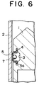
- a typical means for rotating the bobbin together with the spindle is such that, as shown in Fig. 7, a cap 43 is disposed within a recess 42 formed in an upper portion of a spindle 41 with part of it protruding outside of the circumferential surface of the spindle 41 with a coil spring 44 disposed within the recess 42 (for example, see Japanese Patent Application Laid-open No. 47-9817).
- the spring force of the coil spring 44 is set so that the cap 43 is biased toward a bobbin 45 without any slippage between the spindle 41 and the bobbin 45 in a fully wound condition.
- the bobbin 45 is always held at a constant force (for example, 1.6 kgf per cap) or more. Accordingly, when the bobbin 45 is to be mounted on the spindle 41 and the bobbin 45 is pulled off of the spindle 41, a large force is required. For this reason, in the case where the ball pickup work (bobbin exchange work) is performed automatically, it is necessary to increase the pulling force or the insertion force and the bobbin holding force of the bobbin exchanging device. As a result, there is a problem that power consumption is increased and the overall apparatus is enlarged. Also, conventional systems suffer from a problem that the load imposed on a worker is increased where the bobbin exchange work is performed manually.
- an object of the present invention is to provide a spindle for a spinning machine, which can prevent a bobbin from slipping even if rotational speed changes are significant during the starting or a stopping of rotation, and in addition which can decrease the pulling force and insertion force on the bobbin when exchanging bobbins.
- a spindle for a spinning machine is characterized by comprising: an engagement piece received in a recess formed in a circumferential surface of the spindle, a portion of which projects outside of the circumferential surface to engage with an inner surface of a bobbin inserted onto the spindle; a resilient member causing a biasing force, that can prevent slippage of the bobbin, to act on the engagement piece when rotational speed changes are great during the starting and stopping of spindle rotation; and a mass body having such a weight that the sum of the biasing force of the resilient member and a biasing force caused by centrifugal force in the engagement piece can prevent slippage between a full bobbin and the engagement piece when the full bobbin is rotated.
- the engagement piece provided in the spindle is kept in a pressing condition on the inner surface of the bobbin inserted onto the spindle by the biasing force of the resilient member. Also, when the rotational speed of the spindle reaches a predetermined level or greater, the engagement piece is kept in the pressing condition by the biasing force caused by the centrifugal force applied to the mass body and the biasing force of the resilient member. Accordingly, in a stopped condition, the force required when the bobbin is pulled off of the spindle against the biasing force of the resilient member and when the bobbin is inserted onto the spindle becomes smaller than that for the conventional spindle using a coil spring.
- a plurality of recesses are formed at equal intervals in the circumferential surface of the spindle. Consequently, slippage between the bobbin and the spindle can be positively prevented.
- the engagement piece is a cap detachably mounted in the recess so that an amount of projection from the recess of a tip end portion is variable.
- the cap detachably mounted in the recess functions as the engagement piece. Accordingly, in comparison with the arrangement in which the engagement piece also serves as the mass body, the task of inserting the bobbin on the spindle and the task of pulling the bobbin from the spindle may be performed smoothly.
- the resilient member and the mass body are not in engagement with each other. Consequently, the manufacture thereof may be facilitated.
- the mass body is formed into a spherical shape. Therefor, the manufacture of the mass body is facilitated and can be readily obtained.
- the resilient member is a coil spring and the mass body is disposed inside of the coil spring. Consequently, the mass body may move inside of the coil spring and the coil spring may serve as the guide of the mass body.
- the engagement piece is formed as a leaf spring and also serves as the resilient member.
- the number of parts may be reduced and assembly work may be facilitated.
- a guide portion is provided in the cap for guiding the mass body in a radial direction of the spindle.
- the centrifugal force applied to the mass body is effectively applied as a biasing force for pressing the inner surface of the bobbin to the cap.
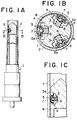
- a gap ⁇ is formed between an outer circumferential surface of a spindle 1 and an inner circumferential surface of a bobbin 2 inserted onto the spindle 1.
- a plurality (three in the first embodiment) of recesses 3 are formed at equal intervals in an upper portion of the spindle 1.
- the recesses 3 are formed substantially into cylindrical shapes so as to be perpendicular to a rotary axis of the spindle 1.
- Annular grooves 4 are formed in the inner circumferential surfaces of the recesses 3.
- a cap 5 is received in each recess 3 as an engagement piece. A part of the cap 5 projects outside of the circumferential surface of the spindle 1.
- the cap 5 has a pair of flanged portions 5a each having a smaller thickness than the width of the groove 4.
- the flanged portions 5a are detachably mounted in the recess 3 in engagement with the groove 4.
- the cap 5 is mounted so that the amount of projection of the tip end portion from the recess 3 may be changed by a difference between the thickness of the flanged portions 5a and the width of the groove 4. As shown in Fig. 2, in the cap 5, cutaways 5b are formed at opposite positions.
- the cap 5 may be bent by depressing both sides of the cap 5 at opposite positions (positions of the flanged portions 5a) displaced 90° from the positions where the cutaways 5b are formed. Accordingly, upon assembling the cap 5, the flanged portions 5a of the cap 5 are engaged with the groove 4 by inserting the flanged portions 5a into the recess 3 under the condition that the cap 5 is bent.
- a coil spring 6 to be used as a resilient member is disposed in each recess 3 so that it is in contact with the inner surface of the cap 5 and the bottom surface of the recess 3.
- the spring force of the coil spring 6 is set so as to make it possible to apply a biasing force to the cap 5 which can prevent slippage of the bobbin 2 even if rotational speed changes are great during the starting and stopping of spindle rotation.
- the spring force of the coil spring 6 is set at a minimum level that may meet the requirements of the above-described biasing force.
- This level is changed depending upon the weight of the bobbin 2 to be used, the frictional force between the bottom portion 2a of the bobbin 2 and the spindle 1, the frictional force between the inner surface of the bobbin 2 and the cap 5, or the deceleration conditions when stopping rotation or the acceleration conditions when starting rotation of the spindle 1. This level may be determined through experiments in advance or theoretically.
- a spherical ball 7 to be used as a mass member is received in each recess 3.
- the ball 7 is formed to have a diameter that is somewhat smaller than the inner diameter of the coil spring 6, and is disposed inside of the coil spring 6. Since the ball 7 is provided out of engagement with the coil spring 6, the ball 7 may move inside of the coil spring 6 along with the coil spring 6.
- the ball 7 is formed to have a minimum weight so that the sum of the biasing force of the coil spring 6 to the cap 5 during rotation when the bobbin 2 is full and the biasing force caused by the centrifugal force of the ball 7 can prevent slippage between a fully wound bobbin 2 and the cap 5.
- the bobbin 2 is held from inside by having its upper inner surface pressed by the cap 5 and is rotated together with the spindle 1.
- the magnitude of the pressure from the cap 5 needed so that slippage between the spindle 1 and the bobbin 2 is not generated is related to the weight of the bobbin 2 which includes the rotational speed of the spindle 1 and the wound thread. Then, the higher the rotational speed of the spindle 1, the larger the pressure that will be needed. Also, in the case where the rotational speed is kept at the same level, the larger the weight of the bobbin 2, the larger the pressure that will be needed.
- Fig. 3 is a graph showing the relationship between the pressure (bobbin holding force) of the cap 5 to the bobbin 2 and the spindle rotational speed.
- the dotted line indicates a spindle according to the prior art (conventional case A) using coil springs
- the broken line indicates the case of a spindle according to the prior art (conventional case B) using the balls
- the solid line indicates the case of the spindle 1 according to the first embodiment of the present invention.
- the position indicated by F1 in the vertical axis indicates the bobbin holding force required for normal rotation when the bobbin is full.
- the holding force of the invention is designed to be larger than F1.
- the position indicated by F2 indicates the bobbin holding force (biasing force) required during the starting and stopping of rotation.
- the spindle 1 When the spindle 1 is rotated, the combined or resultant force of the spring force of the coil spring 6, the centrifugal force applied to the ball 7 in accordance with the rotation of the spindle 1 and the centrifugal force applied to the cap 5 itself is applied to the cap 5. Then, in the first embodiment, during the starting and stopping of rotation where the rotational speed of the spindle 1 is low, the slippage between the bobbin 2 and the spindle 1 is suppressed mainly by the spring force of the coil spring 6. Since the rotational speed of the spindle 1 is low when starting rotation, the centrifugal force applied to the ball 7 is small but the rotational speed change of the spindle 1 is large.
- the brake force is applied when the rotational speed is lowered down to a predetermined speed to stop the spindle 1. Also in this case, since the rotational speed of the spindle 1 is low, the centrifugal force applied to the ball 7 is low but the rotational speed change of the spindle 1 is large. Accordingly, in both cases, the slippage between the bobbin 2 and the spindle 1 is suppressed by the spring force of the coil spring 6 without depending upon the centrifugal force applied to the ball 7.
- the slippage between the bobbin 2 and the spindle 1 is prevented mainly by the resultant force of the centrifugal force applied to the ball 7 and the spring force of the coil spring 6.
- the spring force of the coil spring 6 and the mass of the ball 7 are set so that the slippage between the bobbin 2 and the spindle 1 can be prevented during rotation when the bobbin is full. Accordingly, even under the conditions where the spindle 1 is rotated at a high speed when the bobbin is almost full, slippage between the bobbin 2 and the spindle 1 can be positively prevented.
- the bobbin 2 is pressingly held to the spindle 1 only by the spring force of the coil spring 6.
- This pressure is smaller than the pressure required to prevent slippage between the bobbin 2 and the spindle 1 when a full bobbin is rotated. Accordingly, the force required to pull an inserted full bobbin off from the spindle 1 and the force required to insert (press) an empty bobbin onto the spindle 1 are small in comparison with the forces required for a conventional spindle using a coil spring.
- the first embodiment has the following advantages.
Landscapes
- Engineering & Computer Science (AREA)
- Mechanical Engineering (AREA)
- Textile Engineering (AREA)
- Spinning Or Twisting Of Yarns (AREA)
Applications Claiming Priority (2)
| Application Number | Priority Date | Filing Date | Title |
|---|---|---|---|
| JP33703697A JPH11172535A (ja) | 1997-12-08 | 1997-12-08 | 紡機のスピンドル |
| JP33703697 | 1997-12-08 |
Publications (2)
| Publication Number | Publication Date |
|---|---|
| EP0926277A2 true EP0926277A2 (fr) | 1999-06-30 |
| EP0926277A3 EP0926277A3 (fr) | 1999-12-15 |
Family
ID=18304842
Family Applications (1)
| Application Number | Title | Priority Date | Filing Date |
|---|---|---|---|
| EP98122585A Withdrawn EP0926277A3 (fr) | 1997-12-08 | 1998-12-03 | Broche pour un métier à filer |
Country Status (4)
| Country | Link |
|---|---|
| EP (1) | EP0926277A3 (fr) |
| JP (1) | JPH11172535A (fr) |
| CN (1) | CN1225955A (fr) |
| TW (1) | TW427338U (fr) |
Cited By (1)
| Publication number | Priority date | Publication date | Assignee | Title |
|---|---|---|---|---|
| CN105544029A (zh) * | 2016-03-07 | 2016-05-04 | 苏州廖若机电科技有限公司 | 一种握持纺织筒管的锭杆装置 |
Families Citing this family (22)
| Publication number | Priority date | Publication date | Assignee | Title |
|---|---|---|---|---|
| DE10248929A1 (de) * | 2002-10-15 | 2004-04-29 | Wilhelm Stahlecker Gmbh | Spulenhülsenkupplung an Spinn- oder Zwirnspindeln |
| DE102004031253A1 (de) * | 2004-06-29 | 2006-01-19 | Texparts Gmbh | Hülsenkupplung |
| CN102774697A (zh) * | 2012-07-31 | 2012-11-14 | 太仓仕禾线网制造有限公司 | 滚珠固定绕线筒的络丝机 |
| CN103215707B (zh) * | 2013-04-15 | 2016-03-23 | 常州市同和纺织机械制造有限公司 | 自动落纱粗纱机的粗纱管插装结构 |
| CN103966710B (zh) * | 2014-05-14 | 2016-05-11 | 湖州石淙印染有限公司 | 一种握持和定位纺织筒管的锭杆 |
| CN103952811B (zh) * | 2014-05-14 | 2016-08-24 | 汪建建 | 一种可定位纺织筒管的锭杆 |
| CN104088046B (zh) * | 2014-07-24 | 2016-08-24 | 吴江市纺织科技中心有限公司 | 一种胀轴纱锭 |
| CN104131373A (zh) * | 2014-08-08 | 2014-11-05 | 湖州市菱湖石淙永盛丝织厂 | 一种带有减震装置的锭子 |
| CN104153064B (zh) * | 2014-08-08 | 2016-07-13 | 仪征金鹰纺织有限公司 | 一种无锭杆的锭子与配套的筒管 |
| CN104120520B (zh) * | 2014-08-08 | 2016-08-24 | 重庆恒进源茧丝绸有限公司 | 一种可固定不同内径筒管的纺织锭子 |
| CN104131372A (zh) * | 2014-08-08 | 2014-11-05 | 湖州市菱湖石淙永盛丝织厂 | 一种可吸震的锭子 |
| CN106884237B (zh) * | 2017-03-07 | 2019-03-12 | 福建长源纺织有限公司 | 一种自动换纱锭细纱机、方法和应用 |
| CN107879189B (zh) * | 2017-10-13 | 2019-06-04 | 扬州康宁光纤光缆有限公司 | 一种电力用电缆线高效率收卷装置 |
| CN108545539B (zh) * | 2018-03-05 | 2019-10-25 | 青岛华尊机械股份有限公司 | 一种织物面料生产用线筒夹持装置 |
| CN108385249B (zh) * | 2018-05-15 | 2021-03-02 | 嘉兴市奇丝奇纺织品织造股份有限公司 | 一种便于夹紧的纺织用纱架 |
| JP7162459B2 (ja) * | 2018-07-23 | 2022-10-28 | 株式会社豊田自動織機 | リング式紡機のリング/トラベラ系 |
| CN110453323B (zh) * | 2019-07-26 | 2021-09-21 | 青岛天诺机电有限公司 | 纱锭与纱管的配合结构 |
| CN110436271B (zh) * | 2019-08-15 | 2020-10-30 | 浙江富兴服装有限公司 | 一种纺织用易调节型纱筒 |
| CN111017611B (zh) * | 2019-12-20 | 2020-08-07 | 舒氏集团有限公司 | 一种pvc电气胶带及其生产设备 |
| CN111304790B (zh) * | 2020-03-28 | 2024-10-15 | 经纬智能纺织机械有限公司 | 一种铝套管及弹性体支持器的组合结构 |
| CN113897729B (zh) * | 2021-09-30 | 2023-09-15 | 莆田市织明新材料科技有限公司 | 一种智能双面提花针织机 |
| CN113896038B (zh) * | 2021-10-04 | 2023-08-08 | 临沂银岭纺织制线有限公司 | 一种自动落纱装置的智能纺织机械 |
Family Cites Families (3)
| Publication number | Priority date | Publication date | Assignee | Title |
|---|---|---|---|---|
| CH418923A (de) * | 1963-04-17 | 1966-08-15 | Winkler Juan Leon | Einrichtung zum Aufspulen von Textilfäden |
| CH403590A (de) * | 1963-04-17 | 1965-11-30 | Winkler Juan Leon | Einrichtung zum Aufspulen von Textilfäden |
| CH686046A5 (de) * | 1992-07-27 | 1995-12-15 | Rieter Ag Maschf | Spindel fur Ringspinn- oder Ringzwirnmaschine |
-
1997
- 1997-12-08 JP JP33703697A patent/JPH11172535A/ja active Pending
-
1998
- 1998-10-29 TW TW88220092U patent/TW427338U/zh unknown
- 1998-12-03 EP EP98122585A patent/EP0926277A3/fr not_active Withdrawn
- 1998-12-08 CN CN 98126994 patent/CN1225955A/zh active Pending
Cited By (1)
| Publication number | Priority date | Publication date | Assignee | Title |
|---|---|---|---|---|
| CN105544029A (zh) * | 2016-03-07 | 2016-05-04 | 苏州廖若机电科技有限公司 | 一种握持纺织筒管的锭杆装置 |
Also Published As
| Publication number | Publication date |
|---|---|
| EP0926277A3 (fr) | 1999-12-15 |
| JPH11172535A (ja) | 1999-06-29 |
| CN1225955A (zh) | 1999-08-18 |
| TW427338U (en) | 2001-03-21 |
Similar Documents
| Publication | Publication Date | Title |
|---|---|---|
| EP0926277A2 (fr) | Broche pour un métier à filer | |
| KR100300555B1 (ko) | 테이프감기장치 | |
| US6138804A (en) | One-way clutch and auxiliary machine using the same | |
| US3940089A (en) | Sewing machine thread control | |
| CN101899730A (zh) | 用于纺纱机或捻线机的锭子的夹纱装置 | |
| US4848686A (en) | Bobbin tube and package support and bearing unit therefor and filament tape-up system | |
| US4280668A (en) | Thread-storage and delivery device for textile machines | |
| EP0611841A1 (fr) | Dispositif de broche à retordre du fil | |
| EP0730054A1 (fr) | Anneau de filage | |
| CN208803245U (zh) | 一种防止梭芯空转的绕线器 | |
| US4932200A (en) | Rotary ring for spinning machinery | |
| EP1120375A1 (fr) | Dispositif de maintien de bobine, bobineur de fil, dispositif de bobinage de fil, procede de bobinage de fil, et procede de bobinage de fil | |
| CN111485302A (zh) | 夹纱装置和用于夹纱装置的装卸载机构 | |
| CN111218735B (zh) | 纺纱机的锭子装置 | |
| JPS6211204B2 (fr) | ||
| JP2002030531A (ja) | 紡機のスピンドル | |
| JPH0683771U (ja) | 糸条巻取装置 | |
| US4848689A (en) | Package former support device | |
| US4395103A (en) | Film winding device for camera | |
| JPH01104840A (ja) | 紡績用回転リング | |
| JPS5846127Y2 (ja) | 紡機における糸のワキシング装置の退避装置 | |
| JPH05120938A (ja) | テープ巻き装置 | |
| JPH085983Y2 (ja) | 紡糸巻取機におけるボビンホルダ | |
| US3668894A (en) | Slip-clutch | |
| JPS6335730B2 (fr) |
Legal Events
| Date | Code | Title | Description |
|---|---|---|---|
| PUAI | Public reference made under article 153(3) epc to a published international application that has entered the european phase |
Free format text: ORIGINAL CODE: 0009012 |
|
| AK | Designated contracting states |
Kind code of ref document: A2 Designated state(s): AT BE CH CY DE DK ES FI FR GB GR IE IT LI LU MC NL PT SE |
|
| AX | Request for extension of the european patent |
Free format text: AL;LT;LV;MK;RO;SI |
|
| PUAL | Search report despatched |
Free format text: ORIGINAL CODE: 0009013 |
|
| AK | Designated contracting states |
Kind code of ref document: A3 Designated state(s): AT BE CH CY DE DK ES FI FR GB GR IE IT LI LU MC NL PT SE |
|
| AX | Request for extension of the european patent |
Free format text: AL;LT;LV;MK;RO;SI |
|
| STAA | Information on the status of an ep patent application or granted ep patent |
Free format text: STATUS: THE APPLICATION HAS BEEN WITHDRAWN |
|
| 17P | Request for examination filed |
Effective date: 20000427 |
|
| 18W | Application withdrawn |
Withdrawal date: 20000531 |