EP0926295B1 - Appareil de tamisage pour la fabrication du papier - Google Patents
Appareil de tamisage pour la fabrication du papier Download PDFInfo
- Publication number
- EP0926295B1 EP0926295B1 EP98107839A EP98107839A EP0926295B1 EP 0926295 B1 EP0926295 B1 EP 0926295B1 EP 98107839 A EP98107839 A EP 98107839A EP 98107839 A EP98107839 A EP 98107839A EP 0926295 B1 EP0926295 B1 EP 0926295B1
- Authority
- EP
- European Patent Office
- Prior art keywords
- end plate
- members
- rod
- intermediate support
- interval
- Prior art date
- Legal status (The legal status is an assumption and is not a legal conclusion. Google has not performed a legal analysis and makes no representation as to the accuracy of the status listed.)
- Expired - Lifetime
Links
- 239000002994 raw material Substances 0.000 claims description 11
- 230000001105 regulatory effect Effects 0.000 claims description 3
- 238000003466 welding Methods 0.000 description 16
- 238000003756 stirring Methods 0.000 description 4
- 238000004519 manufacturing process Methods 0.000 description 3
- 230000000694 effects Effects 0.000 description 2
- 239000000853 adhesive Substances 0.000 description 1
- 230000001070 adhesive effect Effects 0.000 description 1
- 230000006866 deterioration Effects 0.000 description 1
- 238000012423 maintenance Methods 0.000 description 1
- 230000003014 reinforcing effect Effects 0.000 description 1
Images


Classifications
-
- D—TEXTILES; PAPER
- D21—PAPER-MAKING; PRODUCTION OF CELLULOSE
- D21D—TREATMENT OF THE MATERIALS BEFORE PASSING TO THE PAPER-MAKING MACHINE
- D21D5/00—Purification of the pulp suspension by mechanical means; Apparatus therefor
- D21D5/02—Straining or screening the pulp
- D21D5/16—Cylinders and plates for screens
-
- B—PERFORMING OPERATIONS; TRANSPORTING
- B01—PHYSICAL OR CHEMICAL PROCESSES OR APPARATUS IN GENERAL
- B01D—SEPARATION
- B01D29/00—Filters with filtering elements stationary during filtration, e.g. pressure or suction filters, not covered by groups B01D24/00 - B01D27/00; Filtering elements therefor
- B01D29/11—Filters with filtering elements stationary during filtration, e.g. pressure or suction filters, not covered by groups B01D24/00 - B01D27/00; Filtering elements therefor with bag, cage, hose, tube, sleeve or like filtering elements
- B01D29/13—Supported filter elements
- B01D29/23—Supported filter elements arranged for outward flow filtration
Definitions
- the present invention relates to a paper-making screen apparatus. More particularly, the present invention relates to a paper-making screen apparatus having an improved screen, in which the interval between a first end plate and a second end plate is kept by interval keeping members, and further, ends of rod-shaped members are held by a first and second end plates.
- an interval keeping member is provided between a first annular supporting member and a second annular supporting member to keep an interval between the supporting members, and further, ends of a plurality of rod-shaped members annularly provided are held by and between the first supporting member and the second supporting member.
- An end of the interval keeping member is secured by welding to the first supporting member, and the other end of the interval keeping member, to the second supporting member, respectively (see Fig. 6 of U.S. Patent Application No. 08/741,718).
- the present invention has an object to provide a paper-making screen apparatus for solving the problems as described above.
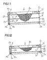
- 1 is a paper-making screen apparatus.
- the paper-making screen apparatus 1 is to separate foreign matters from paper-making raw materials via a screen S.
- paper-making raw materials enter into the apparatus through a paper-making raw materials entry 3 provided in a casing 2, and stirred by a stirring member 4. Foreign matters contained in the paper-making raw materials cannot pass through the screen S; acceptable raw materials pass through meshes of the screen S and are discharged to outside the casing 2 through a paper-making raw materials exit 5 provided in the casing 2. Foreign matters that cannot pass through the meshes of the screen S are discharged to outside the casing 2 from a foreign matter exit 6 provided in the casing 2.
- the stirring member 4 is rotated by a driving force from a motor not shown transmitted through a belt B, a pulley P and a rotating shaft K.
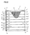
- the screen S has a first annular end plate S 1 located on one end side thereof, and a second annular end plate S 2 located on the other side thereof so that the first end plate S 1 and the second end plate S 2 face each other as shown in Fig. 2.
- a plurality of openings K n for male screws are annularly provided in the second end plate S 2 (the present embodiment has eight openings K n for male screws).
- the first annular end plate S 1 and the second annular end plate S 2 are more specifically, for example, rings.
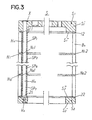
- H n shown in Figs. 2, 3, 6 and 9 are interval keeping members.
- the interval keeping members H n (this embodiment has eight interval keeping members) are secured between the first end plate S 1 and the second end plate S 2 so as to keep an interval between the first end plate S 1 and the second end plate S 12 .
- Female screws M n (this embodiment has eight female screws M n ) are provided on the side of the interval keeping members H n facing the second end plate S 2 .
- V n are male screws engaging with the female screws M n , and there are a plurality of male screws V n , eight in this embodiment.
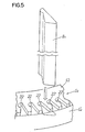
- B n shown in Figs. 4 and 5 are rod-shaped members. An end of a rod-shaped member B n comes into contact with the first end plate S 1 , and the other end thereof, with the second end plate S 2 , respectively.
- a plurality of rod-shaped members B n (in this embodiment, for example, about 500) annularly provided at intervals. An interval is formed between two adjacent rod-shaped members B n .
- the rod-shaped members B n are located outside the interval keeping members H n .
- the rod-shaped members B n are formed, for example, by drawing, and have substantially a uniform sectional shape.
- the ends of the plurality of rod-shaped members B n are held between the first end plate S 1 and the second end plate S 2 held by the plurality of interval keeping members H n , and an interval T of the screen S is formed by adjacent rod-shaped members B n .
- the rod-shaped members B n are adjacent to each other and annularly arranged so as to keep an interval T.
- the first end plate S 1 and the interval keeping members H n are secured by welding as shown by welded portions X in Figs. 2, 3 and 6.
- the second end plate S 2 and the interval keeping members H n are secured in all cases by engaging male screws V n with female screws M n , via openings K n for male screws provided in the second end plate S 2 , thus tightening the second end plate S 2 against the plurality of interval keeping members H n .
- the conventional necessity to weld the first end plate and the interval keeping members is eliminated in a state in which the first end plate and the second end plate holding the ends of the plurality of rod-shaped members in between are pressed by a press or the like. It suffices to engage the male screws V n with the female screws M n , via the openings K n for male screws provided in the second end plate S 2 , thus tightening the second end plate S 2 against the plurality of interval keeping members H n .
- the secured assembly is free from the effect of welding strain, and the interval between adjacent rod-shaped members B n can be kept more uniform than in the conventional art.
- assembly is very easy, and further, when replacing a damaged rod-shaped member after assembly, it suffices to release screw engagement of the male screws V n and the female screws M n by loosening the male screws V n , since they are not secured by welding as in the conventional case, with very easy removal.
- the second end plate S 2 on the male screw V n side is located at the bottom with a view to avoiding, when detaching the screen S to differentiate it from the male screws (not shown) securing the screen S to a screen supporting member 100, operator's erroneous loosening of the male screws V n located on the second end plate S 2 side, which results in dismantling of the screen S.
- first end plate S 1 may be formed integrally, it may also be formed into a configuration, as shown in Fig. 4, for example, in which the first end plate S 1 comprises a first end plate ring S 1 ' and a ring-shaped first end plate contact member S 1 ": the first end plate contact member S 1 " is located closer to the second end plate S 2 than the first end plate ring S 1 ' and comes into contact with the first end plate S 1 ', and the first end plate contact member S 1 " has a plurality of openings 11 for interval keeping members (see Figs. 2 and 3) and a plurality of annularly provided engaging sections 12 for rod-shaped members.
- the first end plate contact member S 1 " is ring-shaped, or more specifically, is of a shape of a ring largely opening including the center of the first end plate contact member S 1 ".
- the engaging sections 12 for the rod-shaped members although Fig. s illustrates only a part of the outer periphery of the first end plate contact member S 1 ", are annularly provided at prescribed intervals throughout the entire outer periphery of the first end plate contact member S 1 " (see Figs. 3, 4, 6 and 9).
- the second end plate S 2 may be formed integrally, it may also be formed into a configuration, as shown in Fig. 5 for example, in which the second end plate S 2 comprises a second end plate ring S 2 ' and a ring-shaped second end plate contact member S 2 ": the second end plate contact member S 2 " is located closer to the first end plate S 1 than the second end plate ring S 2 ' and comes into contact with the second end plate ring S 2 ', and the second end plate contact member S 2 " has a plurality of openings 21 for interval keeping members and a plurality of annularly provided engaging sections 22 for rod-shaped members.
- the second end plate contact member S 2 " is ring-shaped, or more specifically, is of a shape of a ring largely opening including the center of the second end plate contact member S 2 ".
- Fig. 5 illustrates only a part of the outer periphery of the second end plate contact member S 2 "
- the engaging sections 22 (see Figs. 2 and 3) for rod-shaped members are annularly provided at prescribed intervals throughout the entire outer periphery of the second end plate contact member S 2 " (see Figs. 3, 5, 6 and 9).
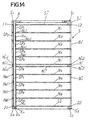
- annular intermediate support members N n are provided between the first end plate contact member S 1 " and the second end plate contact member S 2 ".
- the annular intermediate support members N n have a plurality of openings N n 7 for interval keeping members and a plurality of engaging sections N n 2 for annularly provided rod-shaped members.
- the aforesaid annular intermediate support member N n is ring-shaped, or more specifically, is of the shape of a ring largely opening including the center of the intermediate support member N n .
- the engaging sections N n 2 for rod-shaped members are annularly provided at prescribed intervals throughout the entire outer periphery of the engaging sections N n 2 for rod-shaped members.
- the six intermediate support members N 1 , N 2 , N 3 , N 4 , N 5 and N 6 are sequentially arranged from the first end plate contact member S 1 " toward the second end plate contact member S 2 ".
- the intermediate support member N 1 has a plurality of openings N 1 1 for interval keeping members and a plurality of annularly provided engaging sections N 1 2 for rod-shaped members.
- the intermediate support member N 2 has a plurality of openings N 2 1 for interval keeping members and a plurality of annularly provided engaging sections N 2 2 for rod-shaped members.
- the intermediate support member N 3 has a plurality of openings N 3 1 for interval keeping members and a plurality of annularly provided engaging sections N 3 2 for rod-shaped members.
- the intermediate support member N 4 has a plurality of openings N 4 1 for interval keeping members and a plurality of annularly provided engaging sections N 4 2 for rod-shaped members.
- the intermediate support member N 5 has a plurality of openings N 5 1 for interval keeping members and a plurality of annularly provided engaging sections N 5 2 for rod-shaped members.
- the intermediate support member N 6 has a plurality of openings N 6 1 for interval keeping members and a plurality of annularly provided engaging sections N 6 2 for rod-shaped members.
- the plurality of interval keeping member H n (in this embodiment, there are eight interval keeping members H n ) are provided via the openings 11 for interval keeping members of the first end plate contact member S 1 ", openings for interval keeping members N 1 1, N 2 1, N 3 1, N 4 1, N 5 1 and N 6 1 of the intermediate support members N 1 , N 2 , N 3 , N 4 , N 5 and N 6 , and the openings 21 for interval keeping members of the second end plate contact member S 2 ".
- the interval keeping members H n and the first end plate S 1 are secured, for example, by welding (the welded portions is shown by X in Fig.
- the male screws V n are tightened with the female screws M n so as to prevent the rod-shaped members B n from producing a play.
- a play of the rod-shaped members B n lead to a decrease in performance of the screen resulting from a non-uniform interval from the adjacent rod-shaped member B n , or from producing a play of the rod-shaped members B n during rotation of the screen S 1 resulting in dismantling and breakage of the screen S. Care should be taken not to cause buckling of the rod-shaped members B n as a result of very strong tightening of the male screws V n .
- the male screw V n tops and the second end plate S 2 may be spot-welded to secure the male screw V n , or an adhesive may be coated onto the tightening portions of the male screws V n and the female screws M n to secure the male screws V n to the female screws M n .
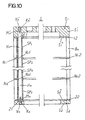
- the interval keeping members H n and the second end plate S 2 are secured by welding as shown in Fig. 6, the interval keeping members H n and the first end plate S 1 , may as required be accomplished by tightening the first end plate S 1 against the plurality of interval keeping members H n through engagement of the male screws V n ' with the female screws M n ' provided in the interval keeping members H n on the side facing the first end plate S 1 via the openings K n provided in the first end plate S 1 , as shown in Fig. 10, in all cases.
- At least two annular intermediate support members N n should be provided between the first end plate contact member S 1 " and the second end plate contact member S 2 ".
- the span holding member group SP n-1 would contain eight members.
- Each component of the span holding member group SP n-1 is more specifically a cylindrical member known as a collar) located on the outer periphery of each of the plurality of interval keeping members H n (in this embodiment, there are eight interval keeping members).
- the span holding member group SP n-1 is provided between the opposed intermediate support members N n , in contact therewith, thereby keeping an interval between the opposed intermediate support members N n .
- Six span holding member groups are therefore arranged: a span holding member group SP 2 between the intermediate support member N 1 and the intermediate support member N 2 , a span holding member group SP 3 between the intermediate support member N 2 and the intermediate support member N 3 , a span holding member group SP 4 between the intermediate support member N 3 and the intermediate support member N 4 , a span holding member group SP 5 between the intermediate support member N 4 and the intermediate support member N 5 , and a span holding member group SP 6 between the intermediate support member N 5 and the intermediate support member N 6 .
- the first span holding member group SP 1 is provided between the first end plate contact member S 1 " and the intermediate support member N 1 on the side closer to the first end plate contact member S 1 ".
- the first span holding member group SP 1 keeps an interval between the opposed first end plate contact member S 1 " and intermediate support member N 1 on the side closer to the first end plate contact member S 1 " by coming into contact with the opposed first end plate contact member S 1 " and intermediate support member N 1 on the side closer to the first end plate contact member S 1 ".
- the first span holding member group SP 1 is located on the outer periphery of each of the interval keeping members H n (the present embodiment has eight interval keeping members H n ).
- a member composing the first span holding member group SP 1 is more specifically a cylinder used for keeping a certain distance between two members, and is a member known as a collar.
- the second span holding member group SP 7 is provided between the second end plate contact member S 2 " and the intermediate support member N 6 on the side closer to the second end plate contact member S 2 ".
- the second span holding member group SP 7 keeps an interval between the opposed second end plate contact member S 2 " and intermediate support member N 6 on the side closer to the second end plate contact member S 2 " by coming into contact with the opposed second end plate contact member S 2 " and intermediate support member N 6 on the side closer to the second end plate contact member S 2 ".
- the second span holding member group SP 7 is located on the outer periphery of each of the interval keeping members H n (the present embodiment has eight interval keeping members H n ).
- a member composing the second span holding member group SP 7 is more specifically a cylinder used for keeping a certain distance between two members, and is a member known as a collar.
- One side ends of the plurality of rod-shaped members B n (there are provided, for example, 500 rod-shaped members) having substantially a uniform cross-section (the term "cross-section” as used here means a surface obtained by cutting in a direction traversing the longitudinal direction of the rod-shaped member B n ) are in contact with the first end plate S 1 as shown in Fig. 4 (more specifically, a plurality of engaging sections 12 for rod-shaped members provided on the first end plate contact member S 1 "), and the other side ends, to the second end plate S 2 (more specifically, a plurality of engaging sections 22 for rod-shaped members provided on the second end plate contact member S 2 ").
- the middle portions of the rod-shaped members B n are engaged, respectively, with a plurality of engaging sections N 1 2 for rod-shaped members provided on the intermediate support member N 1 , a plurality of engaging sections N 2 2 for rod-shaped members provided on the intermediate support member N 2 , a plurality of engaging sections N 3 2 for rod-shaped members provided on the intermediate support member N 3 , a plurality of engaging sections N 4 2 for rod-shaped members provided on the intermediate support member N 4 , a plurality of engaging sections N 5 2 for rod-shaped members provided on the intermediate support member N 5 , and a plurality of engaging sections N 6 2 for rod-shaped members provided on the intermediate support member N 6 .
- the rod-shaped members B n and the intermediate support members H n are arranged in parallel with each other.
- the plurality of openings 11 for interval keeping members and the plurality of engaging sections 12 for rod-shaped members provided in the first end plate contact member S 1 ", the plurality of openings for interval keeping members N 1 1, N 2 1, N 3 1, N 4 1, N 5 1 and N 6 1 and the plurality of engaging sections for rod-shaped members N 1 2, N 2 2, N 3 2, N 4 2, N 5 2 and N 6 2 provided in the intermediate support members N 1 , N 2 , N 3 , N 4 , N 5 and N 6 , and the plurality of openings 21 for interval keeping members and the plurality of engaging sections 22 for rod-shaped members provided in the second end plate contact member S 2 " are formed by cutting by means, for example, of a press, a laser beam or a wire cutter.
- the engaging sections 12 for rod-shaped members, the engaging sections for rod-shaped members N 1 2, N 2 2, N 3 2, N 4 2, N 5 2 and N 6 2, and the engaging sections 22 for rod-shaped members all agree with a part of the sectional shape of the rod-shaped member B n .
- the rod-shaped members B n are free from regulation in the longitudinal direction of the rod-shaped members B n , and movement is regulated in a direction at right angles to the longitudinal direction of the rod-shaped members B n .
- an interval T is kept between two adjacent rod-shaped members B n as shown in Fig. 8.
- This case differs from the foregoing embodiment (Figs. 1 to 10) in that the intermediate support member N is held between the first span holding member group SP 1 and the second span holding member group SP 7 , resulting in the absence of opposed intermediate support members, and hence in the absence of a span holding member group for keeping an interval between opposed intermediate support members by coming into contact therewith.
- one side ends of the plurality of rod-shaped members B n are in contact with the first end plate S 1 and the other side ends, with the second end plate S 2 , respectively.
- These rod-shaped members B n are annularly arranged at intervals. Two adjacent rod-shaped members B n form an interval of the screen S, and ends of the plurality of rod-shaped members B n are held between the first end plate S 1 and the second end plate S 2 .
- the interval keeping members H n pass through the openings N 1 1 for interval keeping members of the intermediate support member N, and secured to the first end plate S 1 and the second end plate S 2 .
- the first span holding member group SP 1 is located on the outer periphery of each of the plurality of interval keeping members H n , provided between the first end plate S 1 and the intermediate support member N, comes into contact with the opposed first end plate S 1 and intermediate support member N, and thus keeps an interval between the opposed first end plate S 1 and intermediate support member N.
- the second span holding member group SP 7 is located on the outer periphery of each of the plurality of interval keeping members H n , is provided between the second end plate S 2 and the intermediate support member N, is in contact with the opposed second end plate S 2 and intermediate support member N to keep an interval between the opposed second end plate S 2 and intermediate support member N.
- the second end plate S 2 and the interval keeping members H n are secured to each other by tightening the second end plate S 2 against the plurality of interval keeping members H n through engagement of the male screws V n with the female screws M n via the openings for male screws provided in the second end plate S 2 in all cases.
- the other ends of the interval keeping members H n are secured by welding to the first end plate S 1 (welded portions are represented by X).
- Ends of the plurality of interval keeping members H n are secured to the first end plate S 1 and the second end plate S 2 , respectively.
- one side ends of the plurality of rod-shaped members B n are in contact with the first end plate S 1 , and the other ends, to the second end plate S 2 , and the rod-shaped members B n are annularly arranged at intervals. Adjacent rod-shaped members B n form meshes of the screen S, and the ends of the plurality of rod-shaped members are held between the first end plate S 1 and the second end plate S 2 .
- the second end plate S 2 and the interval keeping members H n are secured to each other by tightening the second end plate S 2 against the plurality of interval keeping members H n through engagement of the male screws V n with the female screws M n via the openings K n for male screws provided in the second end plate S 2 in all cases, as in the foregoing embodiment.
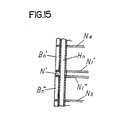
- engaging sections N n 2 for rod-shaped members are provided on the outer periphery of the screen S, and the paper-making raw materials are caused to flow from outside to inside the screen for concentration by bringing the rod-shaped members closer to the stirring member 4.
- the screen is therefore of the outside pressure type (centripetal screen).
- the screen is not limited to the above, but as shown in Fig.
- the engaging section N 4 2 for rod-shaped members may be provided inside the opening for interval keeping member N 4 1 (on the inner periphery of the screen S) and the rod-shaped member B n may be brought closer to the stirring member (not shown), thus adopting a screen known as an inside pressure type one (centrifugal screen) in which the paper-making raw materials are caused to flow from inside to outside the screen S.
- a screen known as an inside pressure type one centrifugal screen
- the rod-shaped members B n are engaged with the plurality of engaging sections 12 provided on the first end plate contact member S 1 ", the plurality of engaging sections for rod-shaped members N 1 2, N 2 2, N 3 2, N 4 2, N 5 2 and N 6 2 provided on the intermediate support members N 1 , N 2 , N 3 , N 4 , N 5 and N 6 , and the plurality of engaging sections 22 for rod-shaped members provided on the second end plate contact member S 2 ".
- the plurality of engaging sections 22 for rod-shaped members provided on the second end plate contact member S 2 ".
- the rod-shaped members B n When conducting engagement, furthermore, the rod-shaped members B n may be damaged, or when the rod-shaped members B n are long in size, or are formed by drawing, the cross-sectional shape cannot be formed uniformly, or the interval between two adjacent rod-shaped members cannot be kept uniform.
- the rod-shaped members B n are divided into first rod-shaped members B n ' and second rod-shaped members B n ", and an intermediate support member for connection N' is provided between the first end plate S 1 and the second end plate S 2 .
- the screen S is used when separating foreign matters from paper-making raw materials, as the paper-making screen apparatus shown in Fig. 1.
- the screen S has an intermediate support member for connection N' 1 1 for interval keeping members between a first annular end plate S 1 located at an end of the screen S and a second annular end plate S 2 located at the other end.
- a plurality of interval keeping members H n (in this embodiment, there are provided eight interval keeping members H n ) pass through the opening N' 1 1 for interval keeping members, are secured to the first end plate S 1 and the second end plate S 2 to keep an interval between the first end plate S 1 and the second end plate S 2 .
- a plurality of first rod-shaped members B n ' having substantially a uniform cross-sectional shape are annularly arranged at intervals between the first end plate S 1 and the intermediate support member N' for connection.
- a plurality of second rod-shaped members B n " having substantially a uniform cross-sectional shape are annularly arranged at intervals between the second end plate S 2 and the intermediate support member N' for connection.
- a mesh is formed by adjacent first rod-shaped members B n ' and adjacent second rod-shaped members B n ".
- the ends of the plurality of rod-shaped members B n ' are held between the first end plate S 1 and the intermediate support member N' for connection.
- the ends of the second rod-shaped members B n " are held between the second end plate S 2 and the intermediate support member N' for connection.
- the second end plate S 2 and the interval keeping members H n are secured to each other by tightening the second end plate S 2 against the plurality of interval keeping members H n through engagement of the male screws V n with the female screws M n via the openings K n for male screws provided in the second end plate S 2 in all cases.
- the interval keeping members H n and the first end plate are secured to each other by welding (welded portions are represented by X in Fig. 14).
- the ends of the plurality of first rod-shaped members B n ' are held between the first end plate S 1 and the intermediate support member N' for connection.
- the ends of the plurality of second rod-shaped members B n " are held between the second end plate S 2 and the intermediate support member N' for connection.
- a mesh of the screen S is formed by adjacent first rod-shaped members B n ' and adjacent second rod-shaped members B n ".
- the first end plate S 1 may be formed integrally.
- the first end plate S 1 may also comprise a first ring-shaped end plate ring S 1 ' and first ring-shaped end plate contact member S 1 ".
- a plurality of ring-shaped engaging sections 12 engaging with the first rod-shaped members B n ' having substantially a uniform cross-sectional shape are formed by cutting by means of a press, a laser beam or a wire cutter on the first end plate contact member S 1 " in contact with the first end plate ring S 1 '.
- a plurality of ring-shaped engaging sections N 1 '2 engaging with the first rod-shaped members B n ' having substantially a uniform cross-sectional shape are formed by cutting by means of a press, a laser beam or a wire cutter.
- the second end plate S 2 may be formed integrally.
- the second end plate S 2 may also comprise a second ring-shaped end plate ring S 2 ' and second ring-shaped end plate contact member S 1 ".
- a plurality of ring-shaped engaging sections 22 engaging with the second rod-shaped members B n " having substantially a uniform cross-sectional shape are formed by cutting by means of a press, a laser or a wire cutter on the second end plate contact member S 2 " in contact with the second end plate ring S 2 " in contact with the second end plate ring S 2 '.
- a plurality of ring-shaped engaging sections N 1 "2 engaging with the second rod-shaped members B n " having substantially a uniform cross-sectional shape are formed by cutting by means of a press, a laser beam, or a wire cutter.
- an end of the first rod-shaped member B n ' is in contact with the engaging section 12 formed by the first end plate ring S 1 ' and the first end plate contact member S 1 ", and other end of the first rod-shaped member B n ' is in contact with, and is supported by, the engaging section N 1 '2 formed by the intermediate support member N for connection and the first intermediate contact member N 1 ' for connection.
- An end of the second rod-shaped member B n " is in contact with the engaging section 22 formed by the second end plate ring S 2 ' and the second end plate contact member S 2 ", and the other end of the second rod-shaped member B n ' is in contact with, and is supported by, the engaging section N 1 "2 formed by the intermediate support member N' for connection and the second intermediate contact member N 1 ".
- the interval between the opposed first end plate S 1 and intermediate support member N 1 closest to the first end plate S 1 is kept, for example, by positioning a first span holding member group SP 1 , comprising a cylindrical collar used for keeping a distance between two members, on the outer periphery of each of the interval keeping members H n , providing the same between the first end plate S 1 , and the intermediate support member N 1 , closest to the first end plate S 1 , and bringing the same into contact with the opposed first end plate S 1 , and intermediate support member N 1 closes to the first end plate S 1 .
- a first span holding member group SP 1 comprising a cylindrical collar used for keeping a distance between two members, on the outer periphery of each of the interval keeping members H n , providing the same between the first end plate S 1 , and the intermediate support member N 1 , closest to the first end plate S 1 , and bringing the same into contact with the opposed first end plate S 1 , and intermediate support member N 1 closes to the first end plate S 1 .
- the interval between the opposed second end plate S 2 and intermediate support member N 8 closest to the second end plate S 2 is kept, for example, by positioning a second span holding member group SP 10 , comprising a cylindrical collar used for keeping a distance between two members, on the outer periphery of each of the interval keeping members H n , providing the same between the second end plate S 2 and the intermediate support member N 8 closest to the second end plate S 2 , and bringing the same into contact with the opposed second end plate S 2 and intermediate support member N 8 closest to the second end plate S 2 .
- a second span holding member group SP 10 comprising a cylindrical collar used for keeping a distance between two members, on the outer periphery of each of the interval keeping members H n , providing the same between the second end plate S 2 and the intermediate support member N 8 closest to the second end plate S 2 , and bringing the same into contact with the opposed second end plate S 2 and intermediate support member N 8 closest to the second end plate S 2 .
- the interval between the opposed members (N 1 and N 2 ), (N 2 and N 3 ), (N 3 and N 4 ), (N 4 and N 1 '), (N 1 " and N 5 ), (N 5 and N 6 ), (N 6 and N 7 ) and (N 7 and N 8 ) is kept, for example, by positioning span holding member groups SP 2 to SP 9 , each comprising a cylindrical collar used for keeping a distance between two members, on the outer periphery of each of the opposed members (N 1 and N 2 ), (N 2 and N 3 ), (N 3 and N 4 ), (N 4 and N 1 '), (N 1 " and N 5 ), (N 5 and N 6 ), (N 6 and N 7 ) and (N 7 and N 8 ), and bringing the same into contact with the opposed members (N 1 and N 2 ), (N 2 and N 3 ), (N 3 and N 4 ), (N 4 and N 1 '), (N" 1 and N 5 ), (N 5 and N 6 ), (N 1 and
- an opening 11 for interval keeping member is provided in the first end plate S 1 ; openings for interval keeping members N 1 1, N 2 1, N 3 1, N 4 1, N 5 1, N 6 1, N 7 1 and N 8 1 are provided in the intermediate support member N; an opening for interval keeping member N 1 ' 1 1 is provided in the first intermediate contact member N 1 ' for connection; an opening for interval keeping member N' 1 1 is provided in the intermediate support member N' for connection; openings for interval keeping members N 1 ' 1 1 and N 1 " 1 1 are provided in the second intermediate contact members N 1 ' and N 1 " for connection; and an opening 21 for interval keeping member is provided in the second end plate S 2 .
- the second end plate and all the interval keeping members on one side of the screen are secured by tightening the second end plate against the plurality of interval keeping members through engagement of the male screws with the female screws via the openings for male screws provided in the second end plate, fixture of at least the side of the interval keeping members facing the second end plate being thus secured without relying upon welding.
- the second members are free from the effect of welding strain, and it is possible to keep uniform intervals between adjacent rod-shaped members as compared with conventional ones.
- the first end plate is composed of the first end plate ring and the first end plate contact member
- the second end plate is composed of the second end plate ring and the second end plate contact member.
- the first end plate is composed of the first end plate ring and the first end plate contact member
- the second end plate is composed of the second end plate ring and the second end plate contact member
- the first end plate contact member, the second end plate contact member, and the intermediate support member comprise identical parts.
Landscapes
- Engineering & Computer Science (AREA)
- Mechanical Engineering (AREA)
- Chemical & Material Sciences (AREA)
- Chemical Kinetics & Catalysis (AREA)
- Paper (AREA)
- Filtration Of Liquid (AREA)
- Combined Means For Separation Of Solids (AREA)
Claims (6)
- Dispositif de tamis pour la fabrication du papier, pour séparer des matières étrangères de matières premières de fabrication de papier à l'aide d'un tamis, comprenant :un tamis (S) comportant :une première plaque d'extrémité annulaire (S1) disposée à une extrémité de celui-ci ;une deuxième plaque d'extrémité annulaire (S2) disposée à l'autre extrémité de celui-ci ;une pluralité d'éléments de maintien d'intervalle (Hn) fixés chacun à ladite première plaque d'extrémité (S1) et à ladite deuxième plaque d'extrémité (S2), de façon à maintenir un intervalle entre ladite première plaque d'extrémité (S1) et ladite deuxième plaque d'extrémité (S2) ;une pluralité d'éléments en forme de tige (Bn) comportant chacun une extrémité en contact avec ladite première plaque d'extrémité (S1), et l'autre extrémité en contact avec ladite deuxième plaque d'extrémité (S2), et disposés de façon annulaire parallèlement les uns aux autres à certains intervalles ;ladite première plaque d'extrémité (S1) et ladite deuxième plaque d'extrémité (S2) supportant les extrémités de ladite pluralité d'éléments en forme de tige entre elles ; caractérisé en ce que :ladite deuxième plaque d'extrémité annulaire (S2) comporte une pluralité d'ouvertures pour des vis mâles ;ladite pluralité d'éléments de maintien d'intervalle (Hn) comportent des vis femelles (Mn) sur le côté regardant vers ladite deuxième plaque d'extrémité (S2) ;ledit tamis (S) comporte de plus une pluralité de vis mâles (Vn) coopérant avec lesdites vis femelles (Mn) ;ladite pluralité de vis mâles (Vn) coopérent avec lesdites vis femelles ; et en ce que ladite deuxième plaque d'extrémité (S2) est fixée auxdits éléments de maintien d'intervalle (Hn) par coopération desdites vis mâles (Vn) par l'intermédiaire d'ouvertures (Kn) pour les vis mâles (Vn) disposées dans ladite deuxième plaque d'extrémité (S2) avec lesdites vis femelles (Mn) et serrage de ladite deuxième plaque d'extrémité (S2) contre ladite pluralité d'éléments de maintien d'intervalle (Hn).
- Dispositif de tamis pour la fabrication du papier selon la revendication 1, dans lequel ledit tamis comporte :un élément de support intermédiaire (N), disposé entre ladite deuxième plaque d'extrémité (S2) et ladite première plaque d'extrémité (S1), et comportant des ouvertures (N11) pour une pluralité d'éléments de maintien d'intervalle (Hn) et des sections d'engagement pour la pluralité d'éléments en forme de tige (Bn) disposés de façon annulaire ;une pluralité d'éléments de maintien d'intervalle (Hn) traversant les ouvertures (N11) pour les éléments de maintien d'intervalle (Hn) dudit élément de support intermédiaire (N), fixés à ladite première plaque d'extrémité (S1) et à ladite deuxième plaque d'extrémité (S2), de façon à maintenir ainsi un intervalle entre ladite première plaque d'extrémité (S1) et ladite deuxième plaque d'extrémité (S2), et comportant chacun des vis femelles (Mn) sur le côté de ceux-ci regardant vers ladite deuxième plaque d'extrémité (S2) ;un premier groupe d'éléments de maintien de portée (SP1), disposés sur la périphérie extérieure de chacun desdits éléments de maintien d'intervalle (Hn), disposés entre ladite première plaque d'extrémité (S1) et ledit élément de support intermédiaire (N), chacun d'entre eux étant en contact avec ladite première plaque d'extrémité (S1) et ledit élément de support intermédiaire (N) regardant vers celle-ci, de façon à maintenir ainsi un intervalle entre ladite première plaque d'extrémité (S1) et ledit élément de support intermédiaire (N) regardant vers celle-ci ; etun deuxième groupe d'éléments de maintien de portée (SP7), disposés sur la périphérie extérieure de chacun desdits éléments de maintien d'intervalle (Hn), disposés entre ladite deuxième plaque d'extrémité (S2) et ledit élément de support intermédiaire (N), chacun d'entre eux étant en contact avec ladite deuxième plaque d'extrémité (S2) et ledit élément de support intermédiaire (N) regardant vers celle-ci, de façon à maintenir ainsi un intervalle entre ladite deuxième plaque d'extrémité (S2) et ledit élément de support intermédiaire (N) regardant vers celle-ci ;lesdits éléments en forme de tige (Bn) coopérant avec les sections d'engagement (Nn2) pour que les éléments en forme de tige (Bn) soient libres de toute régulation dans la direction longitudinale desdits éléments en forme de tige (Bn), et régulés pour le déplacement dans une direction à angle droit de la direction longitudinale des éléments en forme de tige (Bn).
- Dispositif de tamis pour la fabrication du papier selon la revendication 1, dans lequel ledit tamis comporte :au moins deux éléments de support intermédiaires annulaires (Nn), disposés entre ladite deuxième plaque d'extrémité (S2) et ladite première plaque d'extrémité (S1), et comportant des ouvertures (Nn1) pour une pluralité d'éléments de maintien d'intervalle (Hn) et des sections d'engagement (Nn2) pour la pluralité d'éléments en forme de tige (Bn) disposés de façon annulaire ;une pluralité d'éléments de maintien d'intervalle (Hn) traversant les ouvertures (Nn1) pour les éléments de maintien d'intervalle (Hn) dudit élément de support intermédiaire (Nn), fixés à ladite première plaque d'extrémité (S1) et à ladite deuxième plaque d'extrémité (S2), de façon à maintenir ainsi un intervalle entre ladite première plaque d'extrémité (S1) et ladite deuxième plaque d'extrémité (S2), et comportant chacun des vis femelles (Mn) sur le côté de ceux-ci regardant vers ladite deuxième plaque d'extrémité (S2) ;au moins un groupe d'éléments de maintien de portée (SPn), disposés sur la périphérie extérieure de chacun de ladite pluralité d'éléments de maintien d'intervalle (Hn), disposés entre lesdits éléments de support intermédiaires opposés (Nn), et maintenant des intervalles entre lesdits éléments de support intermédiaires opposés (Nn) par venue en contact avec lesdits éléments de support intermédiaires opposés (Nn) ;un premier groupe d'éléments de maintien de portée (SP1), disposés sur la périphérie extérieure de chacun desdits éléments de maintien d'intervalle (Hn), disposés entre ladite première plaque d'extrémité (S1) et ledit élément de support intermédiaire (Nn) le plus proche de ladite première plaque d'extrémité (S1), et venant en contact avec ladite première plaque d'extrémité opposée (S1) et ledit élément de support intermédiaire (N1) le plus proche de ladite première plaque d'extrémité (S1), de façon à maintenir ainsi l'intervalle entre ladite première plaque d'extrémité opposée (S1) et ledit élément de support intermédiaire (N1) le plus proche de ladite première plaque d'extrémité (S1) ; etun deuxième groupe d'éléments de maintien de portée (SP7), disposés sur la périphérie extérieure de chacun desdits éléments de maintien d'intervalle (Hn), disposés entre ladite deuxième plaque d'extrémité (S2) et ledit élément de support intermédiaire (N6) le plus proche de ladite deuxième plaque d'extrémité (S2), et venant en contact avec ladite deuxième plaque d'extrémité opposée (S2) et ledit élément de support intermédiaire (N6) le plus proche de ladite deuxième plaque d'extrémité (S2), de façon à maintenir par conséquent l'intervalle entre ladite deuxième plaque d'extrémité opposée (S2) et ledit élément de support intermédiaire (N6) le plus proche de ladite deuxième plaque d'extrémité ;lesdits éléments en forme de tige (Bn) coopérant avec les sections d'engagement (Nn2) pour que les éléments en forme de tige soient libres de toute régulation dans la direction longitudinale desdits éléments en forme de tige (Bn), et régulés pour le déplacement dans une direction à angle droit par rapport à la direction longitudinale des éléments en forme de tige (Bn).
- Dispositif de tamis pour la fabrication du papier pour séparer des matières étrangères de matières premières de fabrication de papier à l'aide d'un tamis, comprenant :caractérisé en ce que :un tamis (S) comportant :une première plaque d'extrémité annulaire (S1) disposée à une extrémité de celui-ci ;une deuxième plaque d'extrémité annulaire (S2) disposée à l'autre extrémité de celui-ci ;un élément de support intermédiaire pour le raccordement (N'), disposé entre ladite deuxième plaque d'extrémité (S2) et ladite première plaque d'extrémité (S1), et comportant des ouvertures pour des éléments de maintien d'intervalle (Hn) ;une pluralité d'éléments de maintien d'intervalle (Hn), traversant lesdites ouvertures pour les éléments de maintien d'intervalle (Hn), fixés à ladite première plaque d'extrémité (S1) et à ladite deuxième plaque d'extrémité (S2), de façon à maintenir un intervalle entre ladite première plaque d'extrémité (S1) et ladite deuxième plaque d'extrémité (S2), et comportant chacun des vis femelles sur le côté de ceux-ci regardant vers ladite deuxième plaque d'extrémité (S2) ;une pluralité de premiers éléments en forme de tige (Bn') disposés de façon annulaire parallèlement les uns aux autres à certains intervalles entre ladite première plaque d'extrémité (S1) et ledit élément de support intermédiaire (N') pour le raccordement ; etune pluralité de deuxièmes éléments en forme de tige (Bn") disposés de façon annulaire parallèlement les uns aux autres à certains intervalles entre ladite deuxième plaque d'extrémité (S2) et ledit élément de support intermédiaire (N') pour le raccordement ;des extrémités de ladite pluralité d'éléments en forme de tige (Bn') étant maintenues entre ladite première plaque d'extrémité (S1) et ledit élément de support intermédiaire (N') pour le raccordement, et des extrémités de ladite pluralité de deuxièmes éléments en forme de tige (Bn") étant maintenues entre ladite deuxième plaque d'extrémité (S2) et ledit élément de support intermédiaire (N') pour le raccordement,ladite deuxième plaque d'extrémité annulaire ((S2) S2) comporte une pluralité d'ouvertures pour des vis mâles ;ladite pluralité d'éléments de maintien d'intervalle (Hn) comportent des vis femelles (Mn) sur le côté de ceux-ci regardant vers ladite deuxième plaque d'extrémité (S2) ;ledit tamis (S) comporte de plus une pluralité de vis mâles (Vn) coopérant avec lesdites vis femelles (Mn) ;ladite deuxième plaque d'extrémité (S2) étant fixée auxdits éléments de maintien d'intervalle (Hn) par coopération desdites vis mâles (Vn) par l'intermédiaire d'ouvertures (Kn) pour les vis mâles (Vn) disposées dans ladite deuxième plaque d'extrémité (S2) avec lesdites vis femelles (Mn) et serrage de ladite deuxième plaque d'extrémité (S2) contre ladite pluralité d'éléments de maintien d'intervalle (Hn).
- Dispositif de tamis pour la fabrication du papier selon l'une quelconque des revendications 1 à 3, dans lequel :ladite première plaque d'extrémité (S1) comprend un premier anneau de plaque d'extrémité (S1') et un premier élément de contact de plaque d'extrémité (S1") ;ledit premier élément de contact de plaque d'extrémité (S1") est en contact avec ledit premier anneau de plaque d'extrémité (S1'), et comporte une pluralité d'ouvertures pour des éléments de maintien d'intervalle (Hn) et une pluralité de sections d'engagement pour des éléments en forme de tige (Bn') disposés de façon annulaire ;ladite deuxième plaque d'extrémité (S2) comprend un deuxième anneau de plaque d'extrémité (S2') et un deuxième élément de contact de plaque d'extrémité (S2") ;ledit deuxième élément de contact de plaque d'extrémité (S2") est en contact avec ledit deuxième anneau de plaque d'extrémité (S2"), et comporte une pluralité d'ouvertures pour des éléments de maintien d'intervalle et une pluralité de sections d'engagement pour des éléments en forme de tige (Bn") disposés de façon annulaire ; etladite pluralité d'ouvertures pour les éléments de maintien d'intervalle (Hn) et ladite pluralité de sections d'engagement pour des éléments en forme de tige. (Bn') disposées de façon annulaire dudit premier élément de contact de plaque d'extrémité (S1") et dudit deuxième élément de contact de plaque d'extrémité (S2") sont formées par découpage à l'aide d'une presse, d'un faisceau laser ou d'un dispositif de coupe à fil.
- Dispositif de tamis pour la fabrication du papier selon l'une quelconque des revendications 2 et 3, dans lequel :ladite première plaque d'extrémité (S1) comprend un premier anneau de plaque d'extrémité (S1') et un premier élément de contact de plaque d'extrémité (S1") ;ledit premier élément de contact de plaque d'extrémité (S1") est en contact avec ledit premier anneau de plaque d'extrémité (S1') et comporte une pluralité d'ouvertures pour des éléments de maintien d'intervalle (Hn) et une pluralité de sections d'engagement pour des éléments en forme de tige (Bn') disposés de façon annulaire ;ladite deuxième plaque d'extrémité (S2) comprend un deuxième anneau de plaque d'extrémité (S2') et un deuxième élément de contact de plaque d'extrémité (S2") ;ledit deuxième élément de plaque de contact d'extrémité (S2") est en contact avec ledit deuxième anneau de plaque d'extrémité (S2'), et comporte une pluralité d'ouvertures pour des éléments de maintien d'intervalle (Hn) et une pluralité de sections d'engagement pour des éléments en forme de tige (Bn") disposés de façon annulaire ; etledit élément de support intermédiaire (N), ladite pluralité d'ouvertures pour des éléments de maintien d'intervalle (Hn) et ladite pluralité de sections d'engagement pour des éléments en forme de tige (Bn') disposés de façon annulaire dudit premier élément de contact de plaque d'extrémité (S1") et dudit deuxième élément de plaque de contact d'extrémité (S2") sont formées par découpage avec une presse, un faisceau laser ou un dispositif de coupe à fil, et ledit premier élément de contact de plaque d'extrémité (S1"), ledit deuxième élément de plaque de contact d'extrémité (S2") et ledit élément de support intermédiaire (N) constituent la même partie.
Applications Claiming Priority (4)
| Application Number | Priority Date | Filing Date | Title |
|---|---|---|---|
| JP35675697 | 1997-12-25 | ||
| JP35675697 | 1997-12-25 | ||
| JP06170498A JP3286592B2 (ja) | 1997-12-25 | 1998-03-12 | 製紙用スクリーン装置 |
| JP6170498 | 1998-03-12 |
Publications (2)
| Publication Number | Publication Date |
|---|---|
| EP0926295A1 EP0926295A1 (fr) | 1999-06-30 |
| EP0926295B1 true EP0926295B1 (fr) | 2003-01-22 |
Family
ID=26402766
Family Applications (1)
| Application Number | Title | Priority Date | Filing Date |
|---|---|---|---|
| EP98107839A Expired - Lifetime EP0926295B1 (fr) | 1997-12-25 | 1998-04-29 | Appareil de tamisage pour la fabrication du papier |
Country Status (9)
| Country | Link |
|---|---|
| US (1) | US6051103A (fr) |
| EP (1) | EP0926295B1 (fr) |
| JP (1) | JP3286592B2 (fr) |
| KR (1) | KR19990062403A (fr) |
| CN (1) | CN1096526C (fr) |
| CA (1) | CA2236722C (fr) |
| DE (1) | DE69810887T2 (fr) |
| FI (1) | FI981361A7 (fr) |
| TW (1) | TW418268B (fr) |
Families Citing this family (20)
| Publication number | Priority date | Publication date | Assignee | Title |
|---|---|---|---|---|
| US6930277B2 (en) * | 1997-09-10 | 2005-08-16 | Velcro Industries B.V. | Fastener element molding |
| US6138838A (en) | 1998-05-29 | 2000-10-31 | J&L Fiber Services, Inc. | Screen media and a screening passage therefore |
| US6367723B1 (en) * | 2000-02-07 | 2002-04-09 | The Fitzpatrick Company | Size reduction machine having an adjustable impeller and screen holder |
| JP2001347108A (ja) * | 2000-06-06 | 2001-12-18 | Aikawa Iron Works Co Ltd | 円筒形状のスクリ−ン及びリング片の形成方法 |
| US6915910B2 (en) * | 2001-04-16 | 2005-07-12 | J&L Fiber Services, Inc. | Screen cylinder and method |
| JP2002346430A (ja) * | 2001-05-23 | 2002-12-03 | Mitsubishi Heavy Ind Ltd | スクリーンシリンダの製作方法、スクリーン、および材料ふるい分け装置 |
| SE519079C2 (sv) * | 2001-05-30 | 2003-01-07 | Metso Paper Inc | Sil för silning av massasuspensioner innefattande en stödring med konisk yta |
| JP2003010608A (ja) * | 2001-07-05 | 2003-01-14 | Aikawa Iron Works Co Ltd | 円筒形状のスクリ−ン |
| JP4376151B2 (ja) * | 2004-08-09 | 2009-12-02 | 相川鉄工株式会社 | スクリーン装置 |
| US20090020461A1 (en) * | 2005-05-09 | 2009-01-22 | Filtration Fibrewall Inc. | Screen Basket with Replaceable Profiled Bars |
| JP5465181B2 (ja) | 2007-11-14 | 2014-04-09 | フィルトレーション・ファイバーウォール・インコーポレーテッド | スクリーンバスケット |
| US20090211965A1 (en) * | 2008-02-21 | 2009-08-27 | Weatherford/Lamb, Inc. | Arrangement for splicing panels together to form a cylindrical screen |
| US9023456B2 (en) | 2011-03-18 | 2015-05-05 | Bilfinger Water Technologies, Inc. | Profiled wire screen for process flow and other applications |
| DE102013010959B3 (de) * | 2013-07-01 | 2014-08-07 | Andritz Fiedler Gmbh | Siebvorrichtung |
| DE102014011679A1 (de) * | 2013-08-20 | 2015-02-26 | Andritz Fiedler Gmbh | Profilierter Siebstab und Siebvorrichtung aus profilierten Siebstäben |
| EP3847715B1 (fr) | 2018-09-07 | 2026-04-15 | 3M Innovative Properties Company | Article de protection contre l'incendie et procédés associés |
| EP3867436A1 (fr) | 2018-10-16 | 2021-08-25 | 3M Innovative Properties Company | Bandes fibreuses non tissées ignifuges |
| WO2021019495A1 (fr) | 2019-08-01 | 2021-02-04 | 3M Innovative Properties Company | Barrières coupe-feu destinées à des blocs de batterie de véhicule électrique |
| DE102019128878B3 (de) * | 2019-10-25 | 2020-07-30 | Voith Patent Gmbh | Siebzylinder |
| CN114982044A (zh) | 2020-01-15 | 2022-08-30 | 3M创新有限公司 | 用于可再充电的电能存储系统的热逸溃屏障 |
Family Cites Families (11)
| Publication number | Priority date | Publication date | Assignee | Title |
|---|---|---|---|---|
| FI80736B (fi) * | 1989-02-16 | 1990-03-30 | Tampella Oy Ab | Foerfarande foer sortering av massasuspension och sorteringsapparat. |
| US4986900A (en) * | 1989-04-04 | 1991-01-22 | A. Ahlstrom Corporation | Sectional screen cylinder |
| US5061370A (en) * | 1990-03-20 | 1991-10-29 | Quebec And Ontario Paper Company Ltd. | Screening device for slurries with improved rotor and hub design |
| US5221437A (en) * | 1991-07-08 | 1993-06-22 | The Black Clawson Company | Screening apparatus for paper making stock |
| JP2968696B2 (ja) * | 1994-12-28 | 1999-10-25 | 相川鉄工株式会社 | 製紙用のスクリーンプレートの製造方法及び製紙用のスクリーンプレート |
| JPH08209574A (ja) * | 1995-01-27 | 1996-08-13 | Aikawa Iron Works Co Ltd | 製紙用のスクリーンプレート |
| JP3190234B2 (ja) * | 1995-09-21 | 2001-07-23 | 相川鉄工株式会社 | 製紙用スクリーン |
| US5791495A (en) * | 1996-03-11 | 1998-08-11 | Beloit Technologies, Inc. | Paper pulp screen cylinder |
| JP3190254B2 (ja) * | 1996-06-20 | 2001-07-23 | 相川鉄工株式会社 | 製紙用スクリ−ン |
| US5799798A (en) * | 1996-08-23 | 1998-09-01 | Chen; Chao-Ho | Screen cylinder for screening high consistency pulp |
| US5798025A (en) * | 1997-03-13 | 1998-08-25 | Ishikawajima-Harima Jukogyo Kabushiki Kaisha | Apparatus for screening waste paper pulp |
-
1998
- 1998-03-12 JP JP06170498A patent/JP3286592B2/ja not_active Expired - Fee Related
- 1998-04-29 DE DE69810887T patent/DE69810887T2/de not_active Expired - Fee Related
- 1998-04-29 EP EP98107839A patent/EP0926295B1/fr not_active Expired - Lifetime
- 1998-05-05 US US09/071,894 patent/US6051103A/en not_active Expired - Fee Related
- 1998-05-05 CA CA002236722A patent/CA2236722C/fr not_active Expired - Fee Related
- 1998-05-13 TW TW087107419A patent/TW418268B/zh not_active IP Right Cessation
- 1998-05-20 KR KR1019980018103A patent/KR19990062403A/ko not_active Ceased
- 1998-06-12 FI FI981361A patent/FI981361A7/fi not_active Application Discontinuation
- 1998-08-14 CN CN98118348A patent/CN1096526C/zh not_active Expired - Fee Related
Also Published As
| Publication number | Publication date |
|---|---|
| US6051103A (en) | 2000-04-18 |
| TW418268B (en) | 2001-01-11 |
| EP0926295A1 (fr) | 1999-06-30 |
| CA2236722A1 (fr) | 1999-06-25 |
| DE69810887T2 (de) | 2003-11-13 |
| FI981361A7 (fi) | 1999-06-26 |
| JPH11241287A (ja) | 1999-09-07 |
| FI981361A0 (fi) | 1998-06-12 |
| CN1221053A (zh) | 1999-06-30 |
| DE69810887D1 (de) | 2003-02-27 |
| KR19990062403A (ko) | 1999-07-26 |
| CN1096526C (zh) | 2002-12-18 |
| CA2236722C (fr) | 2004-07-20 |
| JP3286592B2 (ja) | 2002-05-27 |
Similar Documents
| Publication | Publication Date | Title |
|---|---|---|
| EP0926295B1 (fr) | Appareil de tamisage pour la fabrication du papier | |
| US5372261A (en) | System and method for screening or diverting particulate material | |
| US8297445B2 (en) | Screen basket | |
| AU629881B2 (en) | Modular system | |
| EP1302590B1 (fr) | Raffineur ou dispositif d'agitation pour la fabrication du papier | |
| US5888140A (en) | Torsionally stiff, flexible shaft coupling, especially one made entirely of steel | |
| US5988544A (en) | Rotary grinder cutting block | |
| US6338412B1 (en) | Cylindrical screen, particularly for paper pulp | |
| US5875982A (en) | Refiner having center ring with replaceable vanes | |
| US5806774A (en) | Anvil for centrifugal impact crusher and circle of anvils equipped with such anvils | |
| EP0791395B1 (fr) | Raffineur et procédé de fixation de ses disques | |
| EP1283298A2 (fr) | Raffineur et un procédé pour sa fabrication | |
| JP2911415B2 (ja) | せん断破砕機 | |
| US4069622A (en) | Improvements in or relating to an abrasive wheel | |
| JPH03207457A (ja) | 鉱物破壊機用回転子 | |
| JP2021016808A (ja) | ろ過装置及びその組付方法 | |
| US5960962A (en) | Screen | |
| JP2976806B2 (ja) | セグメント式研削砥石 | |
| JP3114510B2 (ja) | セグメント式研削砥石 | |
| US6142197A (en) | Disc for a disc chipper | |
| US4477031A (en) | Apparatus for ready conversion of crushing cavity configuration in a cone crusher | |
| JP2001522953A (ja) | スクリーンパネル | |
| RU790U1 (ru) | Валково-дисковый ротор | |
| SU1730228A1 (ru) | Пильный барабан дл обработки волокнистых материалов | |
| SU1375316A1 (ru) | Распределитель питани конусной дробилки |
Legal Events
| Date | Code | Title | Description |
|---|---|---|---|
| PUAI | Public reference made under article 153(3) epc to a published international application that has entered the european phase |
Free format text: ORIGINAL CODE: 0009012 |
|
| AK | Designated contracting states |
Kind code of ref document: A1 Designated state(s): DE ES FR GB IT SE |
|
| AX | Request for extension of the european patent |
Free format text: AL;LT;LV;MK;RO;SI |
|
| 17P | Request for examination filed |
Effective date: 19990526 |
|
| AKX | Designation fees paid |
Free format text: DE ES FR GB IT SE |
|
| 17Q | First examination report despatched |
Effective date: 20010607 |
|
| GRAG | Despatch of communication of intention to grant |
Free format text: ORIGINAL CODE: EPIDOS AGRA |
|
| GRAG | Despatch of communication of intention to grant |
Free format text: ORIGINAL CODE: EPIDOS AGRA |
|
| GRAH | Despatch of communication of intention to grant a patent |
Free format text: ORIGINAL CODE: EPIDOS IGRA |
|
| GRAH | Despatch of communication of intention to grant a patent |
Free format text: ORIGINAL CODE: EPIDOS IGRA |
|
| GRAA | (expected) grant |
Free format text: ORIGINAL CODE: 0009210 |
|
| AK | Designated contracting states |
Kind code of ref document: B1 Designated state(s): DE ES FR GB IT SE |
|
| REG | Reference to a national code |
Ref country code: GB Ref legal event code: FG4D |
|
| REF | Corresponds to: |
Ref document number: 69810887 Country of ref document: DE Date of ref document: 20030227 Kind code of ref document: P |
|
| PG25 | Lapsed in a contracting state [announced via postgrant information from national office to epo] |
Ref country code: SE Free format text: LAPSE BECAUSE OF FAILURE TO SUBMIT A TRANSLATION OF THE DESCRIPTION OR TO PAY THE FEE WITHIN THE PRESCRIBED TIME-LIMIT Effective date: 20030422 |
|
| PG25 | Lapsed in a contracting state [announced via postgrant information from national office to epo] |
Ref country code: ES Free format text: LAPSE BECAUSE OF FAILURE TO SUBMIT A TRANSLATION OF THE DESCRIPTION OR TO PAY THE FEE WITHIN THE PRESCRIBED TIME-LIMIT Effective date: 20030730 |
|
| ET | Fr: translation filed | ||
| PLBE | No opposition filed within time limit |
Free format text: ORIGINAL CODE: 0009261 |
|
| STAA | Information on the status of an ep patent application or granted ep patent |
Free format text: STATUS: NO OPPOSITION FILED WITHIN TIME LIMIT |
|
| 26N | No opposition filed |
Effective date: 20031023 |
|
| PGFP | Annual fee paid to national office [announced via postgrant information from national office to epo] |
Ref country code: DE Payment date: 20070423 Year of fee payment: 10 |
|
| PGFP | Annual fee paid to national office [announced via postgrant information from national office to epo] |
Ref country code: GB Payment date: 20070426 Year of fee payment: 10 |
|
| PGFP | Annual fee paid to national office [announced via postgrant information from national office to epo] |
Ref country code: IT Payment date: 20070614 Year of fee payment: 10 |
|
| PGFP | Annual fee paid to national office [announced via postgrant information from national office to epo] |
Ref country code: FR Payment date: 20070416 Year of fee payment: 10 |
|
| GBPC | Gb: european patent ceased through non-payment of renewal fee |
Effective date: 20080429 |
|
| PG25 | Lapsed in a contracting state [announced via postgrant information from national office to epo] |
Ref country code: DE Free format text: LAPSE BECAUSE OF NON-PAYMENT OF DUE FEES Effective date: 20081101 |
|
| REG | Reference to a national code |
Ref country code: FR Ref legal event code: ST Effective date: 20081231 |
|
| PG25 | Lapsed in a contracting state [announced via postgrant information from national office to epo] |
Ref country code: FR Free format text: LAPSE BECAUSE OF NON-PAYMENT OF DUE FEES Effective date: 20080430 |
|
| PG25 | Lapsed in a contracting state [announced via postgrant information from national office to epo] |
Ref country code: GB Free format text: LAPSE BECAUSE OF NON-PAYMENT OF DUE FEES Effective date: 20080429 |
|
| PG25 | Lapsed in a contracting state [announced via postgrant information from national office to epo] |
Ref country code: IT Free format text: LAPSE BECAUSE OF NON-PAYMENT OF DUE FEES Effective date: 20080429 |