EP0926390A2 - Schwingungsverzehrende Vorrichtung - Google Patents
Schwingungsverzehrende Vorrichtung Download PDFInfo
- Publication number
- EP0926390A2 EP0926390A2 EP98309746A EP98309746A EP0926390A2 EP 0926390 A2 EP0926390 A2 EP 0926390A2 EP 98309746 A EP98309746 A EP 98309746A EP 98309746 A EP98309746 A EP 98309746A EP 0926390 A2 EP0926390 A2 EP 0926390A2
- Authority
- EP
- European Patent Office
- Prior art keywords
- coil springs
- mass member
- transmitting
- passage
- accommodating recesses
- Prior art date
- Legal status (The legal status is an assumption and is not a legal conclusion. Google has not performed a legal analysis and makes no representation as to the accuracy of the status listed.)
- Granted
Links
- 230000003139 buffering effect Effects 0.000 title claims abstract description 32
- 230000000717 retained effect Effects 0.000 claims abstract description 6
- 238000006073 displacement reaction Methods 0.000 abstract description 7
- 230000002829 reductive effect Effects 0.000 abstract description 3
- 230000036316 preload Effects 0.000 description 11
- 230000005540 biological transmission Effects 0.000 description 3
- 230000003247 decreasing effect Effects 0.000 description 2
- 239000012530 fluid Substances 0.000 description 2
- 229910000831 Steel Inorganic materials 0.000 description 1
- 238000010009 beating Methods 0.000 description 1
- POIUWJQBRNEFGX-XAMSXPGMSA-N cathelicidin Chemical compound C([C@@H](C(=O)N[C@@H](CCCNC(N)=N)C(=O)N[C@@H](CCCCN)C(=O)N[C@@H](CO)C(=O)N[C@@H](CCCCN)C(=O)N[C@@H](CCC(O)=O)C(=O)N[C@@H](CCCCN)C(=O)N[C@@H]([C@@H](C)CC)C(=O)NCC(=O)N[C@@H](CCCCN)C(=O)N[C@@H](CCC(O)=O)C(=O)N[C@@H](CC=1C=CC=CC=1)C(=O)N[C@@H](CCCCN)C(=O)N[C@@H](CCCNC(N)=N)C(=O)N[C@@H]([C@@H](C)CC)C(=O)N[C@@H](C(C)C)C(=O)N[C@@H](CCC(N)=O)C(=O)N[C@@H](CCCNC(N)=N)C(=O)N[C@@H]([C@@H](C)CC)C(=O)N[C@@H](CCCCN)C(=O)N[C@@H](CC(O)=O)C(=O)N[C@@H](CC=1C=CC=CC=1)C(=O)N[C@@H](CC(C)C)C(=O)N[C@@H](CCCNC(N)=N)C(=O)N[C@@H](CC(N)=O)C(=O)N[C@@H](CC(C)C)C(=O)N[C@@H](C(C)C)C(=O)N1[C@@H](CCC1)C(=O)N[C@@H](CCCNC(N)=N)C(=O)N[C@@H]([C@@H](C)O)C(=O)N[C@@H](CCC(O)=O)C(=O)N[C@@H](CO)C(O)=O)NC(=O)[C@H](CC=1C=CC=CC=1)NC(=O)[C@H](CC(O)=O)NC(=O)CNC(=O)[C@H](CC(C)C)NC(=O)[C@@H](N)CC(C)C)C1=CC=CC=C1 POIUWJQBRNEFGX-XAMSXPGMSA-N 0.000 description 1
- 230000001747 exhibiting effect Effects 0.000 description 1
- 230000002401 inhibitory effect Effects 0.000 description 1
- 238000012986 modification Methods 0.000 description 1
- 230000004048 modification Effects 0.000 description 1
- 238000007789 sealing Methods 0.000 description 1
- 239000010959 steel Substances 0.000 description 1
Images


Classifications
-
- F—MECHANICAL ENGINEERING; LIGHTING; HEATING; WEAPONS; BLASTING
- F16—ENGINEERING ELEMENTS AND UNITS; GENERAL MEASURES FOR PRODUCING AND MAINTAINING EFFECTIVE FUNCTIONING OF MACHINES OR INSTALLATIONS; THERMAL INSULATION IN GENERAL
- F16F—SPRINGS; SHOCK-ABSORBERS; MEANS FOR DAMPING VIBRATION
- F16F15/00—Suppression of vibrations in systems; Means or arrangements for avoiding or reducing out-of-balance forces, e.g. due to motion
- F16F15/10—Suppression of vibrations in rotating systems by making use of members moving with the system
- F16F15/12—Suppression of vibrations in rotating systems by making use of members moving with the system using elastic members or friction-damping members, e.g. between a rotating shaft and a gyratory mass mounted thereon
- F16F15/131—Suppression of vibrations in rotating systems by making use of members moving with the system using elastic members or friction-damping members, e.g. between a rotating shaft and a gyratory mass mounted thereon the rotating system comprising two or more gyratory masses
- F16F15/133—Suppression of vibrations in rotating systems by making use of members moving with the system using elastic members or friction-damping members, e.g. between a rotating shaft and a gyratory mass mounted thereon the rotating system comprising two or more gyratory masses using springs as elastic members, e.g. metallic springs
- F16F15/134—Wound springs
- F16F15/1343—Wound springs characterised by the spring mounting
-
- F—MECHANICAL ENGINEERING; LIGHTING; HEATING; WEAPONS; BLASTING
- F16—ENGINEERING ELEMENTS AND UNITS; GENERAL MEASURES FOR PRODUCING AND MAINTAINING EFFECTIVE FUNCTIONING OF MACHINES OR INSTALLATIONS; THERMAL INSULATION IN GENERAL
- F16F—SPRINGS; SHOCK-ABSORBERS; MEANS FOR DAMPING VIBRATION
- F16F15/00—Suppression of vibrations in systems; Means or arrangements for avoiding or reducing out-of-balance forces, e.g. due to motion
- F16F15/10—Suppression of vibrations in rotating systems by making use of members moving with the system
- F16F15/12—Suppression of vibrations in rotating systems by making use of members moving with the system using elastic members or friction-damping members, e.g. between a rotating shaft and a gyratory mass mounted thereon
- F16F15/131—Suppression of vibrations in rotating systems by making use of members moving with the system using elastic members or friction-damping members, e.g. between a rotating shaft and a gyratory mass mounted thereon the rotating system comprising two or more gyratory masses
- F16F15/13142—Suppression of vibrations in rotating systems by making use of members moving with the system using elastic members or friction-damping members, e.g. between a rotating shaft and a gyratory mass mounted thereon the rotating system comprising two or more gyratory masses characterised by the method of assembly, production or treatment
Definitions
- the present invention relates to a vibration buffering device for mounting between a prime mover and a power transmitting device in order to transmit power from the prime mover to the power transmitting device, and in particular, to a vibration buffering device capable of exhibiting a multi-stage vibration buffering characteristic.
- Vibration buffering devices are conventionally known, for example, from Japanese Patent Application Laid-open Nos.7-71526 and 5-180266.
- the vibration buffering device disclosed in Japanese Patent Application Laid-open No.7-71526 includes a plurality of first coil springs, and a plurality of second coil springs.
- the plurality of second coil springs are formed into an arcuate shape about the rotational axes of first and second mass members and are disposed outside the first coil springs in a radial direction of the mass members. It is required that an intermediate member, for operating the first and second coil springs having different operational radii in operative association with each other, be integrated therewith since the load balance is lost if the intermediate member is divided. Hence, an increase in size cannot be avoided.
- the intermediate member is obliged to be formed into a three-layer structure, resulting in an increase in number of parts.
- a caulking pin or the like is required in order to provide the integrated three-layer structure, which also results in an increased number of parts and in a complicated assembling operation.
- the first and second coil springs are disposed in series in an arcuate configuration about the rotational axes of the first and second mass members.
- the spring load of the second coil spring is set larger than that of the first coil spring.
- the weight of the second coil spring is relatively large. If a preload corresponding to the weight is not applied to the second coil spring, the second coil spring moves to produce a noise.
- the first and second coil springs are connected in series, if a large preload is applied to the second coil spring, a preload applied to the first coil spring is also large, whereby the vibration buffering effect is degraded.
- the present invention has been accomplished with the problems described above in mind. It is therefore an object of the present invention to provide a vibration buffering device which is constructed in a lightweight and compact fashion, so that the generation of a noise can be prevented, the number of parts can be reduced, and the assembling operation can be simplified.
- a vibration buffering device mounted between a prime mover and a power transmitting device to transmit power from the prime mover to the power transmitting device.
- the vibration buffering device comprises a first mass member connected to one of the prime mover and the power transmitting device.
- a damper housing is mounted in the first mass member and has a passage. The passage is annular about a rotational axis of the first mass member and opens radially inwards of the first mass member.
- the damper housing also has a plurality of sets of accommodating recesses which are formed into an arcuate shape about the rotational axis and which open into the passage in pairs.
- a second mass member is connected to the other of the prime mover and the power transmitting device and is capable of being angularly displaced about the same axis relative to the first mass member.
- a plurality of spring holders are slidably inserted into the passage and have a circumferential length substantially corresponding to a distance between the sets of the accommodating recesses.
- a plurality of first coil springs are inserted into the passage while being retained on the spring holder, so that opposite ends thereof are in contact with the spring holder in a power non-transmitting state.
- a plurality of second coil springs are accommodated in the sets of accommodating recesses, respectively, so that opposite ends thereof are in contact with circumferentially opposite ends of the sets of accommodating recesses and circumferentially opposite ends of the spring holder in the power non-transmitting state.
- a plurality of transmitting arms are placed into the passage, so that the opposite ends of the first coil spring are in contact with the transmitting arms in the power non-transmitting state.
- the plurality of transmitting arms are coupled to the second mass member and are formed to have a circumferential length smaller than the distance between the sets of the accommodating recesses, so that the transmitting arms can be brought into contact with one ends of the second coil springs in response to the relative rotation of the first and second mass members.
- each of the transmitting arms is turned relative to the damper housing while compressing each of the first coil springs to come into abutment against one end of each of the second coil springs. During this time, power is transmitted between the first and second mass members while being buffered by the first coil spring.
- each transmitting arm compresses the second coil spring in such a manner that the spring holder is slid within the passage with the first coil spring remaining compressed, thereby causing power to be transmitted between the first and second mass members while being buffered by the second coil spring.
- a two-stage vibration buffering characteristic can be provided by the first and second coil springs.
- each of the transmitting arms is formed to have a circumferential length which is smaller than the distance between the sets of the accommodating recesses. Hence, each transmitting arm has a small size.
- the spring holder may be also of a simple shape and a small size, and can be slid in the passage while retaining the small first coil spring. Further, a conventionally required caulking pin or the like is not required, and a caulking operation or the like is not required, leading to a decreased number of parts and a simplified assembling operation.
- the vibration buffering device can be constructed in a lightweight and compact fashion.
- each of the second coil springs is received by the opposite ends of each set of the accommodating recesses in the power non-transmitting state. Hence, even if a preload is applied to the second coil spring, so that movement is not produced, the preload of the second coil spring cannot influence the first coil spring. Thus, it is possible to prevent the generation of a noise due to movement, by applying the preload to the second coil spring so that movement of the second coil spring is not produced.
- each of the first coil springs is disposed in a region corresponding to a diameter of the second coil spring in a radial direction of the first mass member.
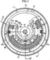
- the vibration buffering system includes first and second mass members 11 and 12 which are capable of being angularly displaced relative to each other about the same axis.
- a prime mover (not shown) is connected to the first mass member 11 to transmit an output therefrom, and a power transmitting device (not shown) is connected to the second mass member 12.
- the first mass member 11 comprises a) a first rotary disk 13 which is formed into a ring plate shape and which has a bearing housing portion 13a in an inner periphery thereof, and b) a cover 14 which is welded to a portion of an inner surface of the first rotary disk 13 near an outer periphery.
- a gear 15 is coupled to the outer periphery of the first rotary disk 13.
- the second mass member 12 comprises a cylindrical rotary shaft 16 having one end coaxially passed through the first rotary disk 13, and a second rotary disk 17 welded to the other end of the rotary shaft 16 to cover the cover 14.
- a cap 18 is mounted at an opening at one end of the rotary shaft 16.
- An input shaft 19, of the power transmitting device, is inserted into the rotary shaft 16.
- the rotary shaft 16 and the input shaft 19 are coupled to each other for non-rotation relative to each other.
- a seal bearing 20 is interposed between the first rotary disk 13 in the first mass member 11 and an outer surface of the rotary shaft 16 and is accommodated in the beating housing portion 13a of the inner periphery of the first rotary disk 13.
- the first mass member 11 is carried on the rotary shaft 16 through the seal bearing 20 for angular displacement relative to each other.
- a bearing which does not have a sealing function, may be accommodated in the bearing housing portion 13a, and a seal member, which is different from the bearing, may be provided between the first rotary disk 13 and the rotary shaft 16.
- a damper housing 21 is formed at a portion of the first mass member 11 near the outer periphery thereof by the first rotary disk 13 and the cover 14.
- An annular passage 22 having a center provided by a rotational axis of the first mass member 11, i.e., a rotational axis of the rotary shaft 16 is defined in the damper housing 21, so that it opens radially inwards of the first mass member 11.
- Two sets of accommodating recesses 23, 24; 23, 24 are also defined in the damper housing 21 in an arcuate shape about the rotational axis of the first mass member 11.
- the set of the accommodating recesses 23 are defined in the inner surface of the first rotary disk 13 into arcuate shapes about the rotational axis of the first mass member 11, so that the recesses 23 are spaced apart through an angle of, for example, about 33 degree from each other.
- the set of accommodating recesses 24 are defined in the inner surface of the cover 14 in arcuate shapes corresponding to those of the accommodating recesses 23.
- a transmitting plate 25 is coupled to the second mass member 12, so that it is superposed on an inner surface of an inner periphery of the second rotary disk 17 in the second mass member 12.
- An annular seal member 26 is interposed between the inner periphery of the cover 14 in the first mass member 11 and the transmitting plate 25.
- the cover 14 and the transmitting plate 25 are sealed therebetween by the seal member 26, and the first rotary disk 13 and the rotary shaft 16 are sealed therebetween by the seal bearing 20, whereby the inside of the damper housing 21 is brought into a sealed state.
- a viscous fluid is encapsulated in the damper housing 21, so that spring holders 28, first coil springs 29 and second coil springs 30, which will be described hereinafter, are submerged in the viscous fluid.
- a pair of spring holders 28 are slidably Inserted in the passage 22.
- the spring holder 28 is formed, for example, by pressing of a steel plate, and integrally provided with (1) a sliding-contact plate portion 28a which is in sliding contact with an inner surface of an outer periphery of the passage 22, (2) a pair of opposed plate portions 28b connected to the sliding-contact plate portion 28a and opposed to each other at a distance smaller than the width of the passage 22 along the rotational axis of the first mass member 11, and (3) a pair of retaining plate portions 28c which are connected to the sliding-contact plate portion 28a to come into sliding contact with an inner side of the passage 22 which are opposed to each other along the rotational axis of the first mass member 11.
- the retaining plate portions 28c are connected to a central portion of the sliding-contact plate portion 28a extending in a circumferential direction of the passage 22.
- Rectangular windows 28d are provided in central portions of the opposed plate portions 28b extending in the circumferential direction of the passage 22.
- the lengths of the sliding-contact plate portion 28a and the opposed plate portions 28b, extending in the circumferential direction of the passage 22 are set substantially in correspondence to the distance between the two sets of the pairs of accommodating recesses 23, 24; 23, 24.
- the first coil spring 29 is retained on the spring holders 28. More specifically, the first coil spring 29 is accommodated in both windows 28d in such a manner that it is sandwiched between the pair of retaining plate portions 28c. In a power non-transmitted state, in which there is no relative angular displacement between the first and second mass members 11 and 12, opposite ends of the first coil spring 29 are in contact with opposite ends of each of the windows 28d in the circumferential direction of the passage 22. In this state, a small preload may be applied to the first coil spring 29.
- the second coil springs 30, having a larger spring load than that of the first coil spring 29, are accommodated in the two set of the pairs of accommodating recesses 23, 24; 23, 24, respectively.
- the second coil springs 30 are formed into an arcuate shape about the rotational axes of the mass members 11 and 12. In the power non-transmitted state, the second coil springs 30 are accommodated in the sets of the accommodating recesses 23, 24; 23, 24 in such a manner that their opposite ends are in contact with the opposite ends of the accommodating recesses 23 and 24 and the circumferentially opposite ends of the spring holders 28.
- the first coil springs 29 are retained on the spring holders 28, so that they are disposed within a region corresponding to the diameter of the second coil springs 30 in a radial direction of the first mass member 11.
- the transmitting plate 25 is integrally provided with a pair of transmitting arms 31 which extend outwards along a diametrical line of the transmitting plate 25. Tip ends of the transmitting arms 31 are placed into the passage 22 in such a manner that they are relatively slidably fitted between the opposed plate portions 28b in the spring holders 28. The lengths of the tip ends of the transmitting arms 31 in the circumferential direction of the passage 22 are set smaller than the distance between the sets of the accommodating recesses 23 and 24.
- a pair of clamping plate portions 31a are formed at the tip ends of the transmitting arms 31, and bifurcated so that each of them sandwiches corresponding one of the first coil springs 29 retained on the spring holders 28 from opposite sides. In the power non-transmitting state, the opposite ends of the first coil spring 29 are in contact with both the clamping plates 31a, and the clamping plates 31a are at locations spaced apart from the ends of the second coil springs 30.
- a pair of stoppers 32 are integrally provided in an inward projecting manner on the first rotary disk 13 of the first mass member 11 radially inside each of the sets of the accommodating recesses 23 and 24, so that they are located centrally between the transmitting arms 31 in the circumferential direction in the power non-transmitting state.
- the stoppers 32 can be put into abutment against the transmitting arms 31 to limit the amount of relative angular displacement of the first and second mass members 11 and 12.
- the first rotary disk 13 is formed by pressing, and the stoppers 32 are obliged to be formed, so that the diameter of tip ends thereof is slightly smaller.
- the radially outer surfaces of the first rotary disk 13 is formed as a surface perpendicular to a direction of rotation of the transmitting arms 31.
- the transmitting arms 31 After the transmitting arms 31 have been put into abutment against one of the ends of the second coil springs 30, the transmitting arms 31 compress the second coil springs 30 with the first coil springs 29 remaining compressed, so that the spring holders 28 are slid within the passage 22.
- the power is transmitted between the first and second mass members 11 and 12, while the vibration is being buffered by the second coil springs 30.
- a two-stage vibration buffering characteristic can be provided by the first and second coil springs 29 and 30.
- each of the transmitting arms 31 is formed to have a circumferential length smaller than the distance between the sets of the accommodating recesses 23 and 24 and thus, has a small size.
- Each of the spring holders 28 may be also of a simple shape and a small size, such that it can be slid in the passage 22, while retaining the small first coil spring 29. Therefore, a conventionally required caulking pin or the like is not required, and a caulking operation is not required, either, leading to a decreased number of parts and a simplified assembling operation.
- the vibration buffeting device can be constructed in a lightweight and compact fashion.
- each of the second coil springs 30 is received by the opposite ends of each set of the accommodating recesses 23 and 24 in the power non-transmitting state. Even if a preload is applied to the second coil springs 30, so that movement is not produced, the preload on the second coil springs 30 cannot influence the first coil springs 29. Therefore, it is possible to prevent the generation of a noise due to movement by applying the preload to the second coil springs 30, so that movement is not produced in the second coil springs 30.
- first coil springs 29 are disposed in the region corresponding to the diameter of the second coil springs 30 in the radial direction of the first mass member 11, it is possible to prevent a force in the rotational direction from being applied to the spring holder 28 by the first and second coil springs 29 and 30.
- a point of application of the load from the first coil spring 29 to the spring holder 28 and a point of application of the load from the second coil spring 30 to the spring holder 28 are at locations offset from each other in the radial direction of the first mass member 11, a force for rotating the spring holder 28 about an axis parallel to the rotational axis of the first mass member 11 is applied from the first and second coil springs 29 and 30 to the spring holder 28.
- the point of application of the load from the first coil spring 29 to the spring holder 28 exists in an area of the point of application of the load from the second coil spring 30 to the spring holder 28 since the first coil springs 29 are disposed in the region corresponding to the diameter of the second coil springs 30 in the radial direction of the first mass member 11.
- the first coil springs 29 are disposed in the region corresponding to the diameter of the second coil springs 30 in the radial direction of the first mass member 11.
- the stoppers 32 for inhibiting the relative rotation of the mass members 11 and 12 are provided on the first rotary disk 13 of the first mass member 11 radially inside the sets of the accommodating recesses 23 and 24, the stoppers 32 are disposed by effectively utilizing an unoccupied space produced inside an area where the first and second coil springs 29 and 30 are disposed.
- the first and second coil springs 29 and 30 can be disposed at a required distance radially toward the outside of the mass members 11 and 12.
- Fig. 7 is a partially cutaway front view of a vibration buffering device according to a second embodiment of the present invention
- Fig.8 is a sectional view taken along a line 8-8 in Fig.7, wherein portions or components corresponding to those in the first embodiment are designated by like reference characters.
- the damper housing 21 is provided at a portion of a first mass member 11 near the outer periphery thereof, and has an annular passage 22 which opens radially inwards of the first mass member 11 and two sets of pairs of accommodating recesses 23 and 24.
- the second coil springs 30 and third coil springs 33, concentrically surrounding the second coil springs 30, are accommodated as concentric double layers in the respective sets of accommodating recesses 23 and 24.
- the spring load of the third coil springs 33 is set larger than that of the second coil spring 30.
- the length of the second coil spring 30 in a circumferential direction of the passage 22 is larger than the length of the third coil springs 33.
- Each of the sets of accommodating recesses 23 and 24 is formed, at opposite ends thereof, with first receiving portions 34 for receiving opposite ends of each of the second coil springs 30 in the power non-transmitting state, and second receiving portions 35 disposed inside the first receiving portions 34 in the circumferential direction of the passage 22 for receiving opposite ends of each of the third coil springs 33 in the power non-transmitting state.
- the opposite ends of the spring holders 28 for retaining the first coil springs 29 are in contact with the opposite ends of the second coil springs 30.
- one of the ends of the third coil springs 33 is brought into contact with the transmitting arms 31 subsequent to the contact of one of the ends of the second coil springs 30 with the transmitting arms 31.
- the transmitting arms 31 are put into abutment against one of the ends of the third coil springs 33 to compress the third coil springs 33. Therefore, a three-stage buffering characteristic can be obtained.
- first mass member 11 is connected to the prime mover and the second mass member 12 is connected to the power transmitting device
- first mass member 11 may be connected to the power transmitting device
- second mass member 12 may be connected to the prime mover
- a two-stage vibration buffering characteristic can be provided by the first and second coil springs.
- each of the transmitting arms is formed to have the circumferential length smaller than the distance between the sets of the accommodating recesses and hence, is of a small size.
- the spring holder also may be of a simple shape and a small size, and can be slid in the passage while retaining the smaller first coil spring. Therefore, the vibration buffering device can be constructed in a lightweight and compact fashion, the number of parts can be reduced, and the assembling operation can be simplified. Further, a preload can be applied to the second coil spring, so that the movement of the second coil spring is not produced, while avoiding the influence to the first coil spring. Thus, it is possible to prevent the generation of a noise due to the movement
Landscapes
- Engineering & Computer Science (AREA)
- General Engineering & Computer Science (AREA)
- Physics & Mathematics (AREA)
- Acoustics & Sound (AREA)
- Aviation & Aerospace Engineering (AREA)
- Mechanical Engineering (AREA)
- Manufacturing & Machinery (AREA)
- Vibration Prevention Devices (AREA)
- Arrangement Or Mounting Of Propulsion Units For Vehicles (AREA)
Applications Claiming Priority (2)
| Application Number | Priority Date | Filing Date | Title |
|---|---|---|---|
| JP32731397A JP3838598B2 (ja) | 1997-11-28 | 1997-11-28 | 振動緩衝装置 |
| JP32731397 | 1997-11-28 |
Publications (3)
| Publication Number | Publication Date |
|---|---|
| EP0926390A2 true EP0926390A2 (de) | 1999-06-30 |
| EP0926390A3 EP0926390A3 (de) | 2001-06-27 |
| EP0926390B1 EP0926390B1 (de) | 2004-04-28 |
Family
ID=18197752
Family Applications (1)
| Application Number | Title | Priority Date | Filing Date |
|---|---|---|---|
| EP98309746A Expired - Lifetime EP0926390B1 (de) | 1997-11-28 | 1998-11-27 | Schwingungsverzehrende Vorrichtung |
Country Status (4)
| Country | Link |
|---|---|
| US (1) | US6113496A (de) |
| EP (1) | EP0926390B1 (de) |
| JP (1) | JP3838598B2 (de) |
| DE (1) | DE69823471T2 (de) |
Cited By (4)
| Publication number | Priority date | Publication date | Assignee | Title |
|---|---|---|---|---|
| EP1122461A3 (de) * | 2000-01-31 | 2003-06-25 | ZF Sachs AG | Torsionsschwingungsdämpfer |
| EP1703167A1 (de) * | 2005-03-18 | 2006-09-20 | BorgWarner Inc. | Torsionsschwingungsdämpfer |
| DE19964629B3 (de) * | 1999-12-07 | 2014-07-31 | Zf Friedrichshafen Ag | Drehschwingungsdämpfer |
| EP3199829A1 (de) * | 2016-01-27 | 2017-08-02 | Borgwarner Inc. | Torsionsschwingungsdämpfer |
Families Citing this family (14)
| Publication number | Priority date | Publication date | Assignee | Title |
|---|---|---|---|---|
| FR2762058B1 (fr) * | 1997-04-10 | 1999-05-14 | Valeo | Dispositif d'accouplement elastique entre deux arbres sensiblement alignes |
| KR100422630B1 (ko) * | 2001-05-02 | 2004-03-12 | 현대자동차주식회사 | 이중질량 플라이휠 |
| US7343832B2 (en) * | 2003-02-14 | 2008-03-18 | Luk Lamellen Und Kupplungsbau Beteiligungs Kg | Torsional vibration damper |
| ITPD20060059A1 (it) * | 2006-02-24 | 2007-08-25 | Holmac Sas | Dispositivo perfezionato per la rotazione combinata di un albero attorno al proprio asse |
| DE102007063883B3 (de) | 2007-04-20 | 2018-08-09 | Zf Friedrichshafen Ag | Torsionsschwingungsdämpfer |
| DE102007018654B4 (de) | 2007-04-20 | 2018-05-17 | Zf Friedrichshafen Ag | Torsionsschwingungsdämpfer |
| JP5256160B2 (ja) * | 2009-09-30 | 2013-08-07 | アイシン・エィ・ダブリュ工業株式会社 | ダンパ装置及び動力伝達装置 |
| US8523685B2 (en) * | 2010-09-24 | 2013-09-03 | Aisin Seiki Kabushiki Kaisha | Torque fluctuation absorber |
| JP5673460B2 (ja) * | 2011-09-14 | 2015-02-18 | トヨタ自動車株式会社 | 車両用ダンパ装置 |
| CN105393024B (zh) * | 2013-05-23 | 2018-04-03 | 利滕斯汽车合伙公司 | 降低噪音的具有双作用弹簧系统的隔离器 |
| US9234549B2 (en) | 2013-09-13 | 2016-01-12 | Paladin Brands Group, Inc. | Torsional coupling for a mobile attachment device |
| KR101637752B1 (ko) * | 2014-12-01 | 2016-07-20 | 현대자동차주식회사 | 임팩트 스프링 상수가 부여된 토크 필터 및 이를 적용한 보기류 벨트 시스템 |
| USD806132S1 (en) * | 2015-11-09 | 2017-12-26 | Eaton Corporation | Spring slider |
| WO2021138865A1 (zh) * | 2020-01-09 | 2021-07-15 | 舍弗勒技术股份两合公司 | 减振传动机构及动力传动系统 |
Citations (2)
| Publication number | Priority date | Publication date | Assignee | Title |
|---|---|---|---|---|
| JPH05180266A (ja) | 1991-05-23 | 1993-07-20 | Valeo | 特に自動車に適するトーションダンパー |
| JPH0771526A (ja) | 1986-07-05 | 1995-03-17 | Luk Lamellen & Kupplungsbau Gmbh | 振動緩衝装置 |
Family Cites Families (11)
| Publication number | Priority date | Publication date | Assignee | Title |
|---|---|---|---|---|
| DE1425260A1 (de) * | 1962-12-05 | 1968-10-17 | Fichtel & Sachs Ag | Kupplungsscheibe mit einem aus Gummielementen aufgebauten Torsionsschwingungsdaempfer |
| US4548311A (en) * | 1982-09-27 | 1985-10-22 | Borg-Warner Corporation | Vehicle torsional damper having low rate and high rate damping stages |
| AU561285B2 (en) * | 1982-10-13 | 1987-05-07 | Daikin Seisakusho K.K. | A damper disc |
| JPS59123726U (ja) * | 1983-02-09 | 1984-08-20 | 株式会社大金製作所 | ダンパ−デイスク組立体 |
| EP0270980B1 (de) * | 1986-12-06 | 1990-05-23 | Volkswagen Aktiengesellschaft | Schwungmassenanordnung |
| DE3708345A1 (de) * | 1987-03-14 | 1988-09-29 | Voith Gmbh J M | Elastische kupplung |
| DE3723015A1 (de) * | 1987-07-11 | 1989-01-19 | Daimler Benz Ag | Geteiltes schwungrad |
| JPH0645724Y2 (ja) * | 1989-05-02 | 1994-11-24 | 株式会社大金製作所 | ダンパーディスク |
| DE4141723C2 (de) * | 1991-12-20 | 1999-12-16 | Mannesmann Sachs Ag | Torsionsschwingungsdämpfer mit Leerlauffederung |
| JP3618158B2 (ja) * | 1995-12-08 | 2005-02-09 | Nskワーナー株式会社 | トルクコンバータ用ロックアップクラッチのスプリングダンパー装置 |
| JPH1047371A (ja) * | 1996-08-02 | 1998-02-17 | Exedy Corp | ダンパーディスク組立体 |
-
1997
- 1997-11-28 JP JP32731397A patent/JP3838598B2/ja not_active Expired - Fee Related
-
1998
- 1998-11-20 US US09/196,443 patent/US6113496A/en not_active Expired - Fee Related
- 1998-11-27 EP EP98309746A patent/EP0926390B1/de not_active Expired - Lifetime
- 1998-11-27 DE DE69823471T patent/DE69823471T2/de not_active Expired - Lifetime
Patent Citations (2)
| Publication number | Priority date | Publication date | Assignee | Title |
|---|---|---|---|---|
| JPH0771526A (ja) | 1986-07-05 | 1995-03-17 | Luk Lamellen & Kupplungsbau Gmbh | 振動緩衝装置 |
| JPH05180266A (ja) | 1991-05-23 | 1993-07-20 | Valeo | 特に自動車に適するトーションダンパー |
Cited By (4)
| Publication number | Priority date | Publication date | Assignee | Title |
|---|---|---|---|---|
| DE19964629B3 (de) * | 1999-12-07 | 2014-07-31 | Zf Friedrichshafen Ag | Drehschwingungsdämpfer |
| EP1122461A3 (de) * | 2000-01-31 | 2003-06-25 | ZF Sachs AG | Torsionsschwingungsdämpfer |
| EP1703167A1 (de) * | 2005-03-18 | 2006-09-20 | BorgWarner Inc. | Torsionsschwingungsdämpfer |
| EP3199829A1 (de) * | 2016-01-27 | 2017-08-02 | Borgwarner Inc. | Torsionsschwingungsdämpfer |
Also Published As
| Publication number | Publication date |
|---|---|
| US6113496A (en) | 2000-09-05 |
| EP0926390A3 (de) | 2001-06-27 |
| JP3838598B2 (ja) | 2006-10-25 |
| DE69823471T2 (de) | 2005-02-24 |
| DE69823471D1 (de) | 2004-06-03 |
| EP0926390B1 (de) | 2004-04-28 |
| JPH11159575A (ja) | 1999-06-15 |
Similar Documents
| Publication | Publication Date | Title |
|---|---|---|
| EP0926390B1 (de) | Schwingungsverzehrende Vorrichtung | |
| US5873786A (en) | Speed reducer with shock absorbing mechanism | |
| US4594915A (en) | Cycloid transmission assembly | |
| KR100242376B1 (ko) | 진동 완충 메커니즘을 가지는 동력 전달 장치 | |
| US4747800A (en) | Damper disc with serial torsion springs | |
| US4485909A (en) | Multiple stage vibration damper | |
| JPH01206136A (ja) | 分割はずみ車 | |
| US5020647A (en) | Lock-up damper device for torque converter | |
| US4093054A (en) | Belleville damper for torque transmitting coupling device | |
| JP3022578B2 (ja) | プーリ | |
| EP0096488A1 (de) | Drehschwingungsdämpfer mit regelbarer Federsenkung und Reibungsdämpfung | |
| US11619270B2 (en) | Lock-up device for torque converter | |
| CN110352312B (zh) | 变矩器 | |
| JP2005054845A (ja) | ロックアップ装置のダンパー機構 | |
| JP2002181085A (ja) | トルクリミッター付ダンパー組立体 | |
| KR20010007325A (ko) | 자동차용 이중 질량 댐핑 플라이휠 | |
| US4983142A (en) | Double damped flywheel, especially for automotive vehicles | |
| US4533260A (en) | Positioning and play-compensating device for the shaft of an electric motor | |
| JP2698237B2 (ja) | 2質量体式フライホイール | |
| JP4625791B2 (ja) | スプリングシート及びスプリング組立体 | |
| JP3969203B2 (ja) | 動力伝達装置 | |
| JP2000213598A (ja) | トルク伝達装置 | |
| US11549567B2 (en) | Lock-up device for torque converter | |
| JP2000002313A (ja) | 捩じりダンパ | |
| JP2007263315A (ja) | プーリ |
Legal Events
| Date | Code | Title | Description |
|---|---|---|---|
| PUAI | Public reference made under article 153(3) epc to a published international application that has entered the european phase |
Free format text: ORIGINAL CODE: 0009012 |
|
| AK | Designated contracting states |
Kind code of ref document: A2 Designated state(s): DE FR GB |
|
| AX | Request for extension of the european patent |
Free format text: AL;LT;LV;MK;RO;SI |
|
| PUAL | Search report despatched |
Free format text: ORIGINAL CODE: 0009013 |
|
| AK | Designated contracting states |
Kind code of ref document: A3 Designated state(s): AT BE CH CY DE DK ES FI FR GB GR IE IT LI LU MC NL PT SE |
|
| AX | Request for extension of the european patent |
Free format text: AL;LT;LV;MK;RO;SI |
|
| 17P | Request for examination filed |
Effective date: 20011221 |
|
| AKX | Designation fees paid |
Free format text: DE FR GB |
|
| GRAP | Despatch of communication of intention to grant a patent |
Free format text: ORIGINAL CODE: EPIDOSNIGR1 |
|
| GRAS | Grant fee paid |
Free format text: ORIGINAL CODE: EPIDOSNIGR3 |
|
| GRAA | (expected) grant |
Free format text: ORIGINAL CODE: 0009210 |
|
| AK | Designated contracting states |
Kind code of ref document: B1 Designated state(s): DE FR GB |
|
| REG | Reference to a national code |
Ref country code: GB Ref legal event code: FG4D |
|
| REF | Corresponds to: |
Ref document number: 69823471 Country of ref document: DE Date of ref document: 20040603 Kind code of ref document: P |
|
| PG25 | Lapsed in a contracting state [announced via postgrant information from national office to epo] |
Ref country code: GB Free format text: LAPSE BECAUSE OF NON-PAYMENT OF DUE FEES Effective date: 20041127 |
|
| ET | Fr: translation filed | ||
| PLBE | No opposition filed within time limit |
Free format text: ORIGINAL CODE: 0009261 |
|
| STAA | Information on the status of an ep patent application or granted ep patent |
Free format text: STATUS: NO OPPOSITION FILED WITHIN TIME LIMIT |
|
| 26N | No opposition filed |
Effective date: 20050131 |
|
| GBPC | Gb: european patent ceased through non-payment of renewal fee |
Effective date: 20041127 |
|
| PG25 | Lapsed in a contracting state [announced via postgrant information from national office to epo] |
Ref country code: FR Free format text: LAPSE BECAUSE OF NON-PAYMENT OF DUE FEES Effective date: 20050729 |
|
| REG | Reference to a national code |
Ref country code: FR Ref legal event code: ST |
|
| PGFP | Annual fee paid to national office [announced via postgrant information from national office to epo] |
Ref country code: DE Payment date: 20101124 Year of fee payment: 13 |
|
| REG | Reference to a national code |
Ref country code: DE Ref legal event code: R119 Ref document number: 69823471 Country of ref document: DE Effective date: 20130601 |
|
| PG25 | Lapsed in a contracting state [announced via postgrant information from national office to epo] |
Ref country code: DE Free format text: LAPSE BECAUSE OF NON-PAYMENT OF DUE FEES Effective date: 20130601 |